
Summary of Contents for NAVITUS MCL 5.10
- Page 1 Controller with internal Quad-band GSM/GPRS/3G modem MCL 5.10 User manual Version 1.5 UAB NAVITUS LT, Lithuania 2018...
- Page 2 Document revision history Version Date Revision history Controller Firmware version 2015-05-27 First Issue 2016-10-12 Updated power and connection information 2017-07-04 Added functionality 2017-11-13 Byte timeout explained Disclaimer The manufacturer guarantees that the following documentation is correct and intended for the device described.
-
Page 3: Table Of Contents
Table of Contents SAFETY INSTRUCTIONS .......................... 5 APPLICATION AND FUNCTIONALITY ..................... 6 PRINCIPAL COMPONENTS OF THE CONTROLLER MCL 5.10 ............. 8 TECHNICAL CHARACTERISTICS ......................8 CONNECTING INTERFACES ........................9 6.1 CONNECTING A METER .......................... 10 LABELING ..............................10 PARAMETERIZATION GUIDE......................... 11 INITIAL INFORMATION ........................... - Page 4 Signs and Abbreviations AC / DC Alternating Current / Direct Current Access Point Name Circuit Switched Data Electromagnetic Compatibility GPRS General Packet Radio Service Global System for Mobile communications Internet Service Provider Internet Protocol address IMEI International Mobile Equipment Identity Light Emitting Diode Not Available / Not Applicable Personal Computer...
-
Page 5: Safety Instructions
2. Safety Instructions Please ensure you read and understand the installation instructions entirely before attempting to install and configure MCL 5.10. Always disconnect the mains supply while installing or servicing the communication interfaces, antenna or changing SIM card. Only the authorized service persons with adequate qualifications can perform installation, uninstallation and parameterization of the GSM/GPRS controller MCL 5.10. -
Page 6: Application And Functionality
3. Application and Functionality General Information MCL 5.10 controller (further referred to as a controller) is used in AMR systems for automated remote data reading of electricity, heat meters and other electronic devices and data transmission to remote offices. Device does not store, manipulate or alter meter information. The controller has an internal lithium-polymer battery for power failure notification to the remote data center. - Page 7 controllers menu or via parametrization software in “provider settings”. Alarm system (Plug & Play) When any event or alarm is received from the meter interface, the controller sends all the data received from the meter and the controllers information (IMEI, IP) using http protocol to the url address specified in the settings menu “Plug&Play server address”.
-
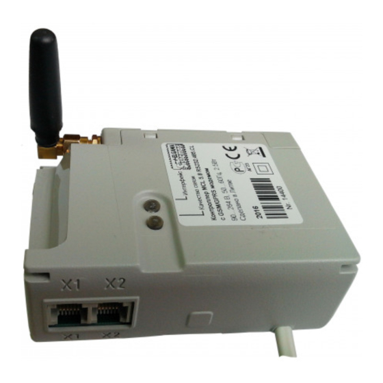
Page 8: Principal Components Of The Controller Mcl 5.10
4. Principal Components of the controller MCL 5.10 The main controller components are listed below: a) Comunication interfaces - RS232 or USB (for parametrization),CL and RS485 for data collection from meters b) Internal 450mAh Li-polymer battery to ensure the notification of power failure or data transfer function support. -
Page 9: Connecting Interfaces
Registered to 3G network G double pulse Signal strength indication*: -113 to -82 dBm or less R pulse (0,4 Hz) -81 to -70 dBm B pulse (0,4 Hz) -69 to -51dBm or more G pulse (0,4 Hz) GSM/GPRS data session active; (connection established) Same color more frequent pulse (2Hz) Interface activity / battery charge indication –... -
Page 10: Connecting A Meter
123 kWh 124 kWh CL / A CL / B RS48 RS48 RS48 MCL 5.10 Figure 4.3.1-1. Meter connection to RS485 interface 7. Labeling Principal controller information is marked on a label. Label explanation: • LED indicator position • Controller name •... -
Page 11: Parameterization Guide
Important! To load or re-load controller’s menu press button ESC (on keyboard) 3 times. 9. Initial Information MCL 5.10 controller using GPRS technology transmits the data of measurement equipment (meters). There is an internal modem with a SIM card socket. - Page 12 Enter a name for the new connection (Figure 6.2-1) Figure 6.2-1 Select a port MCL is connected to (Figure 6.2-2) Figure 6.2-2 After pressing OK in the COM Properties window (figure 6.2-3), the settings are set to Auto detect by default (figure 6.2-4).
- Page 13 Figure 6.2-4 To change the values: 1. Press Disconnect button as shown on figure 6.2-5 (arrow 1); 2. Press Properties button as shown on figure 6.2-5 (arrow 2); Figure 6.2-5...
- Page 14 3. Press Configure button as shown on figure 6.2-6 (arrow 3); 4. Press OK button as shown on figure 6.2-6 (arrow 4); Figure 6.2-6 5. Important. Ensure that other settings of the connection are set as shown on figures 6.2-7; Figure 6.2-7...
- Page 15 6. The settings should change to 19200 8-N-1 as shown on figure 6.2-8 Figure 6.2-8 Important! To load or re-load controller’s menu press button ESC (on keyboard) 3 times.
-
Page 16: Parameterization
10. Parameterization The entire MCL 5.10 menu hierarchy is described in an Annex A. “Controller menu and configuration settings”. Main device functions are further described below. Security Controller parameterization menus are protected with dedicated passwords to prevent from unauthorised access and configuration. - Page 17 Grant menu interface The controller menu can be reached using several interfaces: Wireless, RS485, RS232, USB (depending on the modification). Each menu interface can be enabled (granted) or disabled. To enable interface for controller configuration, set the menu option for the interface value “Grant interface – false”. For example, to disable RS485 menu interface, go to the RS485 out configuration and set the value “Grant menu interface”...
-
Page 18: Annex A. Controller Menu And Configuration Settings
Annex A. Controller menu and configuration settings Important: Menu item availability depends on the user rights and device modification. User rights can be managed only from the admin account secured by the admin password. Menu Item Description SMS command (smscfg:) 0. - Page 19 2. Wireless “in” 0. RETURN Back to the main menu configuration 1. Request to proceed timeout During the specified time the received request has to be send to a meter (through RS485/RS232 out), if it times out the request will be discarded 2.
- Page 20 accepted. This setting is for RS485 out interfaces 7. Answer wait timeout Time for waiting data (answer) in RS485 out, after the request has been sent 8. Next request pause Time for waiting for the next frame in RS485 out, after one frame has been received 9.
- Page 21 Status of the SIM card 9. Battery voltage Battery voltage 10. Battery charging Battery charging 11. Start battery test Start battery test 12. Battery test status Battery test status 10. 13. Read log Read log Table A-1. MCL 5.10 menu item values...
-
Page 22: Annex B. Manufacturer's Guarantee
In case of a power cut, manufacturer ensures, that AMR (Automatic Meter Reading) system equipment will not have any influence on the electricity meter’s data. MCL 5.10 system will restart automatically and will start operating as normal as soon as the voltage is restored.