Cisco IE 3000 Series Hardware Installation Manual
Cisco systems switch installation guide
Hide thumbs
Also See for IE 3000 Series:
- Software configuration manual (760 pages) ,
- Hardware installation manual (186 pages) ,
- Getting started manual (32 pages)
Table of Contents
Advertisement
Advertisement
Table of Contents

Related Manuals for Cisco IE 3000 Series


Summary of Contents for Cisco IE 3000 Series
- Page 1 Cisco IE 3000 Switch Hardware Installation Guide June 2008 Americas Headquarters Cisco Systems, Inc. 170 West Tasman Drive San Jose, CA 95134-1706 http://www.cisco.com Tel: 408 526-4000 800 553-NETS (6387) Fax: 408 527-0883 Text Part Number: OL-13017-01...
- Page 2 Networking Academy, Network Registrar, PCNow, PIX, PowerPanels, ProConnect, ScriptShare, SenderBase, SMARTnet, Spectrum Expert, StackWise, The Fastest Way to Increase Your Internet Quotient, TransPath, WebEx, and the WebEx logo are registered trademarks of Cisco Systems, Inc. and/or its affiliates in the United States and certain other countries.
-
Page 3: Table Of Contents
Management Options Network Configurations Switch Installation C H A P T E R Preparing for Installation Warnings OL-13017-01 1-10 1-10 1-11 1-11 1-12 1-13 1-14 1-15 Cisco IE 3000 Switch Hardware Installation Guide C O N T E N T S... - Page 4 Installing the Switch on a DIN Rail Installing the Switch on the Wall Installing the Switch in a Rack Removing the Switch from a DIN Rail or a Rack Connecting Power and Alarm Circuits Wiring the Protective Ground and DC Power...
- Page 5 Verify Switch Performance Speed, Duplex, and Autonegotiation Autonegotiation and NIC Cabling Distance How to Clear the Switch IP Address and Configuration How to Recover Passwords Finding the Switch Serial Number Technical Specifications A P P E N D I X...
- Page 6 Installing the Switch on a DIN Rail Installing the Switch on a Wall Installing the Switch in a Rack Removing the Switch from a DIN Rail or a Rack Connecting Power and Alarm Circuits Information about the Sealed Relay Device...
- Page 7 Identifying a Crossover Cable Four Twisted-Pair Cable Pinouts for 1000BASE-T Ports Adapter Pinouts Configuring the Switch with the CLI-Based Setup Program A P P E N D I X Accessing the CLI from the Console Port Entering the Initial Configuration Information...
- Page 8 Contents Cisco IE 3000 Switch Hardware Installation Guide viii OL-13017-01...
-
Page 9: Preface
Preface Audience This guide is for the networking or computer technician responsible for installing Cisco IE 3000 series switches. We assume that you are familiar with the concepts and terminology of Ethernet and local area networking. Purpose This guide documents the hardware features of the Cisco IE 3000 switches. It describes the physical and performance characteristics of each switch, explains how to install a switch, and provides troubleshooting information. -
Page 10: Related Publications
Statement 1071 The safety warnings for this product are translated into several languages in the Regulatory Compliance and Safety Information for the Cisco IE 3000 Switch that ships with the product. The EMC regulatory statements are also included in that guide. -
Page 11: Overview
(IEDs). You can mount the switch on a DIN rail in an industrial enclosure, on a wall or panel, and with some restrictions, in a standard 19-inch rack. Its components are designed to withstand extremes in temperature, vibration, and shock that are common in an industrial environment. -
Page 12: Chapter 1 Overview
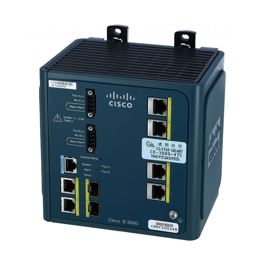
Console Port, page 1-6 • LEDs, page 1-6 • The switch front panel contains the ports, the LEDs, and the power and relay connectors. Figure 1-4 show the switch and expansion module front panels. Cisco IE 3000 Switch Hardware Installation Guide 2-5. - Page 13 Console port Dual-purpose ports Figure 1-2 Power and relay connectors Console port Dual-purpose ports OL-13017-01 Cisco IE-3000-8TC Switch 10/100 ports Protective ground connection Cisco IE-3000-4TC Switch 10/100 ports Protective ground connection Cisco IE 3000 Switch Hardware Installation Guide Front-Panel Description...
- Page 14 Front-Panel Description Figure 1-3 10/100 ports Figure 1-4 100BASE-FX ports Cisco IE 3000 Switch Hardware Installation Guide Cisco IEM-3000-8TM Module Cisco IEM-3000-8FM Module Chapter 1 Overview OL-13017-01...
-
Page 15: 10/100 Ports
In all cases, the attached device must be within 328 feet (100 meters). 100BASE-TX traffic requires Category 5 cable. 10BASE-T traffic can use Category 3 or Category 4 cables. When connecting the switch to workstations, servers, routers, and Cisco IP Phones, be sure that the cable is a straight-through cable. -
Page 16: Console Port
If you want to connect a switch to a terminal, you need to provide an RJ-45-to-DB-25 female DTE adapter. You can order a kit (part number ACS-DSBUASYN=) with that adapter from Cisco Systems. For console-port and adapter-pinout information, see the page C-5. -
Page 17: Setup Led
Chapter 1 Overview Figure 1-6 LEDs on the Cisco IE 3000 Switch Express setup button System LED Alarm LED Setup LED Figure 1-7 10/100 port LED OL-13017-01 Dual-purpose uplink port LED Pwr B LED Pwr A LED Port LED LEDs on the Cisco IEM-3000-8TM Module... - Page 18 Setup Status Switch is configured as a managed switch. Switch is in initial setup. Switch is in initial setup, in recovery, or initial setup is incomplete. Switch failed to start initial setup or recovery because there is no available switch port to which to connect the management station.
-
Page 19: System Led
Power Status LED The switch can operate with one or two DC power sources. Each DC input has an associated LED that shows the status of the corresponding DC input. If power is present on the circuit, the LED is green. If power is not present, the LED color depends on the alarm configuration. -
Page 20: 10/100 Port Status Leds
Front-Panel Description The Pwr A and Pwr B LEDs show that power is not present on the switch if the power input drops below Note the low valid level. The power status LEDs only show that power is present if the voltage at the switch input exceeds the valid level. -
Page 21: Dual-Purpose Port Leds
Compact Flash Memory Card The switch supports a compact flash memory card that makes it possible to replace a failed switch without reconfiguring the new switch. The slot for the compact flash memory card is on the bottom of the switch. See... -
Page 22: Rear-Panel Description
The rear panel of the switch, modules, and power converter have latches for installation on either a DIN rail or a wall. See inward to secure the switch to a DIN rail. The feet stabilize the switch when it is mounted on the wall. Cisco IE 3000 Switch Hardware Installation Guide... -
Page 23: Power Converter (Optional)
The switch can be used with an optional AC/DC power converter. The power converter (PWR-IE3000-AC) can supply 24-VDC power to one switch and up to two modules. The power converter is mounted on the side of a switch and provides power to the switch through a preassembled power cable. -
Page 24: Management Options
Device Manager • You can use the device manager, which is in the switch memory, to manage individual and standalone switches. This web interface offers quick configuration and monitoring. You can access the device manager from anywhere in your network through a web browser. For more information, see the getting started guide and the device manager online help. -
Page 25: Network Configurations
You can manage switches from a SNMP-compatible management station that is running platforms such as HP OpenView or SunNet Manager. The switch supports a comprehensive set of Management Information Base (MIB) extensions and four Remote Monitoring (RMON) groups. See the switch software configuration guide on Cisco.com and the documentation that came with your SNMP... - Page 26 Chapter 1 Overview Network Configurations Cisco IE 3000 Switch Hardware Installation Guide 1-16 OL-13017-01...
- Page 27 Switch Installation This chapter describes how to install your switch, interpret the power-on self-test (POST), and connect the switch to other devices. If your installation is in a hazardous environment, see Caution Environment” Read these topics, and perform the procedures in this order: Preparing for Installation, page 2-1 •...
-
Page 28: Chapter 2 Switch Installation
For connections outside the building where the equipment is installed, the following ports must be Warning connected through an approved network termination unit with integral circuit protection. 10/100/1000 Ethernet Statement 1044 Cisco IE 3000 Switch Hardware Installation Guide Chapter 2 Switch Installation OL-13017-01... -
Page 29: Installation Guidelines
ESD damage to the switch. Do not touch connectors or pins on component boards. Do not touch circuit components inside the switch. When not in use, store the equipment in appropriate static-safe packaging. OL-13017-01 Preparing for Installation... - Page 30 Secure the DIN rail to the mounting surface approximately every 7.8 in. (200 mm), and use end-anchors appropriately. When determining where to place the switch, observe these guidelines: Before installing the switch, first verify that the switch is operational by powering it on and running • POST. Follow the procedures in the For 10/100 ports and 10/100/1000 ports, the cable length from a switch to an attached device cannot •...
-
Page 31: Verifying Package Contents
Note Expansion Module Configurations To increase the number of ports, add one or two expansion modules to the switch. If you are installing only one module, it can be either a Cisco IEM-3000-8TM or a Cisco IEM-3000-8FM. If you are installing two modules, the first must be a Cisco IEM-3000-8TM, and the second can be either a Cisco IEM-3000-8TM or a Cisco IEM-3000-8FM. - Page 32 10/100FE 100FX Figure 2-1 shows example combinations of the Cisco IE-3000-4TC switch and expansion modules. Even though the example configurations in combinations of expansion modules can be used with a Cisco IE-3000-8TC switch. Cisco IE 3000 Switch Hardware Installation Guide...
- Page 33 Chapter 2 Switch Installation Figure 2-1 OL-13017-01 Sample Combinations of Expansion Modules Cisco IE 3000 Switch Hardware Installation Guide Adding Modules to the Switch...
-
Page 34: Connecting Modules
Remove the side panel by firmly grasping both sides of it in the middle and pulling it outward. If Step 1 necessary, use a screwdriver to pry open the side panel. See Figure 2-2 Remove the EMI protective cover from the connector on the switch. See Step 2 Figure 2-3 Cisco IE 3000 Switch Hardware Installation Guide... - Page 35 Push up the upper module latches (at the top of the switch and the module). See the lower module latches (at the bottom of the switch and the module). Figure 2-4 Align the connectors on the switch and the module, and slide the switch and the module together to make Step 4 the connection. See Figure 2-5 Push the upper module latches down and the lower latches up.
-
Page 36: Installing Or Removing The Compact Flash Memory Card
The switches store Cisco IOS software images and switch configurations on a removable flash memory card. You can replace the switch without reconfiguring it. The switch ships with the compact flash memory card installed. Verify that the card is in place on the bottom of the switch. -
Page 37: Verifying Switch Operation
Verifying Switch Operation Before installing the switch in its final location, power on the switch, and verify that the switch passes the power-on self-test (POST). These sections describe the steps required to connect a PC or terminal to the switch console port, to power on the switch, and to observe POST results: •... -
Page 38: Connecting A Pc Or A Terminal To The Console Port
One stop bit • • No parity After you get access to the switch, you can change the port baud rate. See the switch software configuration guide for instructions. Insert the adapter cable in the console port. See Step 3... -
Page 39: Connecting The Protective Ground And Dc Power
• Grounding the Switch To ground the switch to earth ground by using the ground screw, follow these steps. Make sure to follow any grounding requirements at your site. This equipment must be grounded. Never defeat the ground conductor or operate the equipment in the Warning absence of a suitably installed ground conductor. - Page 40 Use a standard Phillips screwdriver or a ratcheting torque screwdriver with a Phillips head to remove the Step 1 ground screw from the front panel of the switch. Store the ground screw for later use. Use a wire-stripping tool to strip the 10-gauge wire to 0.5 inch. (12.7 mm) ± 0.02 inch (0.5 mm). See...
- Page 41 Insert the ground screw into the functional ground screw opening on the front panel. Step 5 Use a ratcheting torque screwdriver to tighten the ground screw and ring terminal lug to the switch front Step 6 panel to 8.5 in-lb. The torque should not exceed 8.5 in-lb. See...
-
Page 42: Wiring The Dc Power Source
You must connect the switch only to a DC-input power source that has an input supply voltage from 18 Caution to 60 VDC. If the supply voltage is not in this range, the switch might not operate properly or might be damaged. - Page 43 Chapter 2 Switch Installation To wire the switch to a DC-input power source, follow these steps: Locate the power and relay connector (see Step 1 Figure 2-12 Identify the positive and return DC power connections on the connector. The positive DC power Step 2 connection is labeled V, and the return is the adjacent connection labeled RT.
- Page 44 Step 6 (above the installed wire leads) to 2 in-lb. See Figure 2-15. Do not over-torque the power and relay connector captive screws. The torque should not exceed 2 in-lb. Caution Cisco IE 3000 Switch Hardware Installation Guide 2-18 OL-13017-01...
- Page 45 (the one connected to RT) to the return terminal on the DC power source. When you are testing the switch, one power connection is sufficient. If you are installing the switch and are using a second power source, repeat...
- Page 46 External device 1, relay wire connection External device 1, relay wire connection Step 8 (Optional) If you plan to connect external alarm devices to the alarm relays and the switch is already installed, go to the Switch Operation” section on page...
-
Page 47: Attach The Power And Relay Connector To The Switch
Step 2 relay connector. When you are testing the switch, one power source is sufficient. If you are installing the switch and are using a second power source, repeat this procedure for the second power and relay connector (Pwr B), which installs just below the primary power connector (Pwr A). -
Page 48: Running Post
Cisco IOS software image loads. If the POST fails, the System LED turns red. POST failures are usually fatal. Call Cisco Systems immediately if your switch does not pass POST. See Note “Obtaining Documentation, Obtaining Support, and Security Guidelines” section on page Disconnect Power After successfully running POST, follow these steps. -
Page 49: Installing The Switch
The switch ships with latches on the rear panel for a mounting on a DIN rail. See Figure 2-18 You can install the switch as a standalone device on the DIN rail or with the expansion modules already connected. You must connect expansion modules to the switch before installing the switch on the DIN rail. - Page 50 Switch Installation Installing the Switch The illustrations in this procedure show how to install the switch as a standalone device. The same steps can be used to install a switch with expansion modules on the DIN rail. To attach the switch to a DIN rail, follow these steps.
- Page 51 Step 2 Push the DIN rail latches. See Figure 2-20 Position the rear panel of the switch directly in front of the DIN rail, making sure that the DIN rail fits Step 3 in the space between the two latches.
- Page 52 Installing the Switch Step 4 Push the DIN rail latches in after the switch is over the DIN rail. See Figure 2-21 If you are using a 15-mm DIN rail, rotate all the feet (see Note Otherwise, rotate all the feet to the recessed positions.
-
Page 53: Installing The Switch On The Wall
15-mm DIN rail Foot in extended position After the switch is mounted on the DIN rail, connect the power and alarm wires, as described in the “Connecting Power and Alarm Circuits” section on page For instructions on how to remove the switch from a DIN rail, see the Note Rail or a Rack”... - Page 54 Switch Installation Installing the Switch If the DIN rail latches are pushed out, push in the DIN rail latches. See Figure 2-23. Step 1 Figure 2-23 Pushing the DIN Rail Latches In Cisco IE 3000 Switch Hardware Installation Guide 2-28 OL-13017-01...
-
Page 55: Installing The Switch In A Rack
Chapter 2 Switch Installation Step 2 Rotate all feet to the recessed positions so that the switch can mount flat on the wall or panel. See Figure 2-22. Step 3 Position the rear panel of the switch against the wall or a panel in the desired location. See Figure 2-24 Place a number-10 screw that you provide through each DIN rail latch, and screw them into the wall. - Page 56 The 19-inch rack adapter is not intended for application in an industrial environment and therefore it will Note not meet the environmental performance specifications for the Cisco IE 3000 switch. To install the switch in a rack, follow these steps: Use the four Phillips machine screws to securely attach the brackets to the rack.
-
Page 57: Removing The Switch From A Din Rail Or A Rack
Step 2 turn the screw driver clockwise. See Push the DIN rail latches at the top of the switch up, and the latches at the bottom of the switch down. Step 3 Pull the switch out, and release the switch from the DIN rail. See OL-13017-01 2-32. -
Page 58: Connecting Power And Alarm Circuits
Step 4 Remove the switch from the DIN rail. Connecting Power and Alarm Circuits After the switch is installed, you are ready to connect the DC power and alarm relays. • Wiring the Protective Ground and DC Power, page 2-32 •... -
Page 59: Wiring The External Alarms
Switch Installation Wiring the External Alarms The alarm relays on the switch are normally open. To connect an external alarm device to the relays, you must connect two relay contact wires to complete an electrical circuit. Because each external alarm device requires two connections to a relay, the switch supports a maximum of two external alarm devices. - Page 60 Torquing the Power and Relay Connector Captive Screws Repeat Step 1 through Step 4 to insert the input and output wires of an additional external alarm device Step 5 into the second power and relay connector. Cisco IE 3000 Switch Hardware Installation Guide 2-34 OL-13017-01...
- Page 61 External device 1, relay wire major alarm connection See the “Attach the Power and Relay Connector to the Switch” section on page 2-21 how to connect the power and relay connector to the front panel. OL-13017-01 Completed Connections for Two External Alarm Devices on the Power and Relay...
-
Page 62: Connecting Destination Ports
• Connecting to 10/100 and 10/100/1000 Ports The switch 10/100/1000 ports automatically configure themselves to operate at the speed of attached devices. If the attached ports do not support autonegotiation, you can explicitly set the speed and duplex parameters. Connecting devices that do not autonegotiate or that have their speed and duplex parameters manually set can reduce performance or result in no linkage. -
Page 63: Installing And Removing Sfp Modules
Installing and Removing SFP Modules These sections describe how to install and remove SFP modules. SFP modules are inserted into SFP module slots on the front of the switch. These field-replaceable modules provide the uplink optical interfaces, send (TX) and receive (RX). -
Page 64: Installing Sfp Modules Into Sfp Module Slots
Insert the SFP module into the slot until you feel the connector on the module snap into place in the rear Step 4 of the slot. See Cisco IE 3000 Switch Hardware Installation Guide 2-38 SFP Module with a Bale-Clasp Latch Figure 2-33. - Page 65 Do not remove the dust plugs from the SFP module port or the rubber caps from the fiber-optic cable Caution until you are ready to connect the cable. The plugs and caps protect the SFP module ports and cables from contamination and ambient light. Cisco IE 3000 Switch Hardware Installation Guide 2-39 OL-13017-01...
-
Page 66: Removing Sfp Modules From Sfp Module Slots
Grasp the SFP module between your thumb and index finger, and carefully remove it from the module Step 5 slot. Place the removed SFP module in an antistatic bag or other protective environment. Step 6 Cisco IE 3000 Switch Hardware Installation Guide 2-40 Figure 2-34. Removing a Bale-Clasp Latch SFP Module by Using a Flat-Blade Screwdriver... -
Page 67: Connecting To Sfp Modules
Insert the other cable end into a fiber-optic receptacle on a target device. Step 3 Observe the port status LED. Step 4 The LED turns green when the switch and the target device have an established link. OL-13017-01 “Connecting to a Dual-Purpose Port” section on page 2-37. -
Page 68: Connecting To A Dual-Purpose Port
If the LED is off, the target device might not be turned on, there might be a cable problem, or there might be a problem with the adapter installed in the target device. See solutions to cabling problems. If necessary, reconfigure and restart the switch or the target device. Step 5 Connecting to a Dual-Purpose Port The dual-purpose port is a single port with two interfaces, one for an RJ-45 cable and another for an SFP module. -
Page 69: Connecting To 100Base-Fx Ports
Connect the other end of the cable to the other device. Step 2 By default, the switch detects whether an RJ-45 connector or SFP module is connected to a dual-purpose port and configures the port accordingly. You can change this setting and configure the port to recognize only an RJ-45 connector or only an SFP module by using the media type interface configuration command. -
Page 70: Connecting The Switch To The Power Converter
Observe the port status LED. Step 4 The LED turns green when the switch and the target device have an established link. The LED turns amber while the STP discovers the network topology and searches for loops. This process takes about 30 seconds, and then the port LED turns green. -
Page 71: Attaching The Power Converter To The Switch
Attaching the Power Converter to the Switch Follow these directions to connect the power converter to the switch: Remove the left side panel of the switch by firmly grasping both sides of it in the middle and pulling it Step 1 outward. -
Page 72: Installing The Power Converter On A Din Rail, Wall, Or Rack Adapter
Installing the Power Converter on a DIN Rail, Wall, or Rack Adapter You install the power converter on a DIN rail, wall, or rack as you would a switch module. You should first attach the power converter to the switch and then install the entire switch assembly on the DIN rail, wall, or rack adapter. -
Page 73: Connecting The Power Converter To An Ac Power Source
Step 1 Position the power clip so that the two-pin connector is over the power converter and the four-pin Step 2 connector is over the switch Pwr A connector, and then slide the power clip into these two connectors. Figure 2-41. -
Page 74: Connecting The Ac Power Cord To The Power Converter
Connecting the Switch to the Power Converter Table 2-2 Europe (International) Color Brown Blue Green/yellow United States Color Black White Green To prepare an AC power cord to connect to the power converter, strip the inner wire insulation to 0.25 inch (6.3 mm) ±... - Page 75 Insert the exposed ground wire lead into the power converter ground wire connection. Ensure that only Step 2 wire with insulation extends from the connector. See OL-13017-01 AC/DC Power Input Terminal Block Cisco IE 3000 Switch Hardware Installation Guide Connecting the Switch to the Power Converter Figure 2-43. Figure 2-44.
- Page 76 Connecting the Switch to the Power Converter Figure 2-44 Ground AC neutral Tighten the ground wire terminal block screw. Step 3 Note The torque should not exceed 10 in-lb. Step 4 Insert the line and neutral wire leads into the terminal block line and neutral connections. See Figure 2-44.
-
Page 77: Connecting The Power Converter To A Dc Power Source
You can also connect the power converter to a DC power source. The power converter adapts the power source voltage to the 24 VDC that the switch requires. Follow these steps to connect the power converter to a DC power source. - Page 78 Connecting the Switch to the Power Converter Figure 2-45 Earth ground wire connection Return wire connection (to DC return) An exposed wire lead from a DC-input power source can conduct harmful levels of electricity. Be sure Warning that no exposed portion of the DC-input power source wire extends from the power and relay connector.
-
Page 79: Applying Power To The Power Converter
The LED on the power converter front panel is green when the unit is operating normally. The LED is off when the unit is not powered or is not operating normally. After the power is connected, the switch automatically begins the power-on self- test (POST), a series of tests that verifies that the switch functions properly. - Page 80 Chapter 2 Switch Installation Where to Go Next Cisco IE 3000 Switch Hardware Installation Guide 2-54 OL-13017-01...
-
Page 81: Chapter 3 Troubleshooting
IE2100 or SNMP application for details. Verify Switch POST Results As the switch powers on, it begins the POST, a series of tests that runs automatically to ensure that the switch functions properly. It might take several minutes for the switch to complete POST. -
Page 82: Verify Switch Leds
Diagnosing Problems If you connect or disconnect the console cable with power applied to the switch or any device on the Warning network, an electrical arc can occur. This could cause an explosion in hazardous location installations. Be sure that power is removed or the area is nonhazardous before proceeding. -
Page 83: Link Status
Transceiver Issues Use only Cisco SFP modules on the switch. Each Cisco module has an internal serial EEPROM that is encoded with security information. This encoding provides a way for Cisco to identify and validate that the module meets the requirements for the switch. -
Page 84: Spanning Tree Loops
Loops can be caused by a unidirectional link. A unidirectional link occurs whenever the traffic sent by the switch is received by its neighbor, but the traffic from the neighbor is not received by the switch. A broken fiber-optic cable, other cabling, or a port issue could cause this one-way communication. -
Page 85: Cabling Distance
To reset the password on the switch: Power off the switch. Power on the switch, and at the same time, press and hold down the Express Setup button until all the system LEDs turn red. Release the Express Setup button, and the switch continues to boot. -
Page 86: Finding The Switch Serial Number
Finding the Switch Serial Number Finding the Switch Serial Number If you contact Cisco Technical Assistance, you need to know the serial number of your switch. See Figure 3-1 version privileged EXEC command to get the switch serial number. Figure 3-1... -
Page 87: Appendix
1. lfm = linear feet per minute. The safety certifications apply only to ambient temperatures under 140°F (60°C). However, the Note Cisco IE 3000 switch can function in the substation and traffic signal installations under the environmental conditions shown in OL-13017-01 A P P E N D I X lists the technical specifications for the switches and modules. -
Page 88: Appendix A Technical Specification
Table A-2 Cisco IE 3000 Series Technical Specifications Environmental Ranges Storage temperature Operating humidity Operating shock Operating altitude Storage altitude Power Requirements DC input voltage Maximum DC input current Power consumption Physical Dimensions Weight Dimensions (W x D x H) - Page 89 IEC 60079-15: 2005, third edition IEC 60079-0: 2004, fourth edition EN 60079-15: 2005 EN 60079-0: 2006 ANSI/ISA 12.12.01-2007 CSA C22.2 no. 213-M1987 UL 60079-15, first edition CAN/CSA E 60079-15: 02 IEC 60079-15: 2001 IEC 60079-0: 2000 Cisco IE 3000 Switch Hardware Installation Guide...
- Page 90 Appendix A Technical Specifications Cisco IE 3000 Switch Hardware Installation Guide OL-13017-01...
-
Page 91: Appendix
Installation In a Hazardous Environment This chapter describes how to install your switch, interpret the power-on self-test (POST), and connect the switch to other devices when in a hazardous environment. Read these topics, and perform the procedures in this order: Preparing for Installation, page B-1 •... -
Page 92: Preparing For Installation
For connections outside the building where the equipment is installed, the following ports must be connected through an approved network termination unit with integral circuit protection. 10/100/1000 Ethernet Statement 1044 Cisco IE 3000 Switch Hardware Installation Guide Appendix B Installation In a Hazardous Environment... - Page 93 The enclosure must meet IP 54 or NEMA type 4 minimum enclosure rating standards. Statement 1063 If you connect or disconnect the console cable with power applied to the switch or any device on the Warning network, an electrical arc can occur.
- Page 94 Statement 1083 This equipment is only suitable for use in Class I, Division 2, Groups A, B, C, D, or nonhazardous Caution locations. Cisco IE 3000 Switch Hardware Installation Guide Statement 1082 Appendix B Installation In a Hazardous Environment OL-13017-01...
-
Page 95: North American Hazardous Location Approval
IEC 364-3. In addition, if equipment is operated in a domestic environment, interference could occur. Installation Guidelines When determining where to place the switch, observe these guidelines. Environment and Enclosure Guidelines: Review these environmental and enclosure guidelines before installation: This equipment is intended for use in a Pollution Degree 2 industrial environment, in overvoltage •... -
Page 96: Other Guidelines
When determining where to place the switch, observe these guidelines: • Before installing the switch, first verify that the switch is operational by powering it on and running POST. Follow the procedures in the For 10/100 ports and 10/100/1000 ports, the cable length from a switch to an attached device cannot •... -
Page 97: Verifying Package Contents
Two power and relay connectors RJ-45 to DB-9 console port adapter cable • To connect the switch functional ground, you need a ring terminal lug (such as Thomas & Bett part Note number RC10-14 or equivalent). If you want to connect a terminal to the switch console port, you need to provide an RJ-45-to-DB-25 female DTE adapter. -
Page 98: Adding Modules To The Switch
Adding Modules to the Switch The Cisco IE-3000-4TC or the Cisco IE-3000-8TC switch can operate as standalone devices with four or eight Fast Ethernet ports, respectively. To increase the number of Fast Ethernet ports by 8 or 16, you can connect the Cisco IEM-3000-8TM and the Cisco IEM-3000-8FM expansion modules. -
Page 99: Expansion Module Configurations
Installation In a Hazardous Environment Expansion Module Configurations To increase the number of ports, add one or two expansion modules to the switch. If you are installing only one module, it can be either a Cisco IEM-3000-8TM or a Cisco IEM-3000-8FM. If you are installing two modules, the first must be a Cisco IEM-3000-8TM, and the second can be either a Cisco IEM-3000-8TM or a Cisco IEM-3000-8FM. - Page 100 Adding Modules to the Switch Figure B-1 Cisco IE 3000 Switch Hardware Installation Guide B-10 Sample Combinations of Expansion Modules Appendix B Installation In a Hazardous Environment OL-13017-01...
-
Page 101: Connecting Modules
Remove the side panel by firmly grasping both sides of it in the middle and pulling it outward. If Step 1 necessary, use a screwdriver to pry open the side panel. See Figure B-2 Remove the EMI protective cover from the connector on the switch. See Step 2 Figure B-3 OL-13017-01... - Page 102 Push up the upper module latches (at the top of the switch and the module). See the lower module latches (at the bottom of the switch and the module). Figure B-4 Align the connectors on the switch and the module, and slide the switch and the module together to make Step 4 the connection. See Figure B-5 Push the upper module latches down and the lower latches up.
-
Page 103: Installing Or Removing The Compact Flash Memory Card
The switches store Cisco IOS software images and switch configurations on a removable flash memory card. You can replace the switch without reconfiguring it. The switch ships with the compact flash memory card installed. Verify that the card is in place on the bottom of the switch. -
Page 104: Verifying Switch Operation
Verifying Switch Operation Before installing the switch in its final location, power on the switch, and verify that the switch passes the power-on self-test (POST). These sections describe the steps required to connect a PC or terminal to the switch console port, to power on the switch, and to observe POST results: •... -
Page 105: Connecting A Pc Or A Terminal To The Console Port
PC application such as HyperTerminal or Procomm Plus—makes communication between the switch and your PC or terminal possible during the POST. If you connect or disconnect the console cable with power applied to the switch or any device on the Warning network, an electrical arc can occur. -
Page 106: Connecting The Protective Ground And Dc Power
Step 6 Start the terminal-emulation software on the PC. Connecting the Protective Ground and DC Power These sections describe the steps required to connect a protective ground and DC power to the switch: Grounding the Switch, page B-17 • Wiring the DC Power Source, page B-19 •... -
Page 107: Grounding The Switch
• Grounding the Switch To ground the switch to earth ground by using the ground screw, follow these steps. Make sure to follow any grounding requirements at your site. This equipment must be grounded. Never defeat the ground conductor or operate the equipment in the Warning absence of a suitably installed ground conductor. - Page 108 Insert the ground screw into the functional ground screw opening on the front panel. Step 5 Use a ratcheting torque screwdriver to tighten the ground screw and ring terminal lug to the switch front Step 6 panel to 8.5 in-lb. See...
-
Page 109: Wiring The Dc Power Source
5A. Statement 1005 Installation of the equipment must comply with local and national electrical codes. Statement 1074 Warning OL-13017-01 Torquing Ground-Lug Screws Cisco IE 3000 Switch Hardware Installation Guide Verifying Switch Operation B-19... - Page 110 You must connect the switch only to a DC-input power source that has an input supply voltage from Caution 18 to 60 VDC. If the supply voltage is not in this range, the switch might not operate properly or might be damaged.
- Page 111 Do not over-torque the power and relay connector captive screws. The torque should not exceed 2 in-lb. Caution OL-13017-01 Figure Inserting Wires in the Power and Relay Connector Power source return connection Figure Cisco IE 3000 Switch Hardware Installation Guide Verifying Switch Operation B-14. Make sure that you cannot see any wire B-15. B-21...
- Page 112 (the one connected to RT) to the return terminal on the DC power source. When you are testing the switch, one power connection is sufficient. If you are installing the switch and are using a second power source, repeat...
- Page 113 External device 1, relay wire connection External device 1, relay wire connection Step 8 (Optional) If you plan to connect external alarm devices to the alarm relays and the switch is already installed, go to the Switch Operation” section on page...
-
Page 114: Attach The Power And Relay Connector To The Switch
Use a ratcheting torque flathead screwdriver to tighten the captive screws on the sides of the power and relay connector. When you are testing the switch, one power source is sufficient. If you are installing the switch and are using a second power source, repeat this procedure for the second power and relay connector (Pwr B), which installs just below the primary power connector (Pwr A). -
Page 115: Running Post
Cisco IOS software image loads. If the POST fails, the System LED turns red. POST failures are usually fatal. Call Cisco Systems immediately if your switch does not pass POST. See Note “Obtaining Documentation, Obtaining Support, and Security Guidelines” section on page Disconnect Power After successfully running POST, follow these steps. -
Page 116: Installing The Switch
Class I, Division 2 installations. Statement 1066 To prevent the switch from overheating, ensure these minimum clearances: Caution – Top and bottom: 4.13 in. (105 mm) –... -
Page 117: Installing The Switch On A Din Rail
Cisco IE 3000 Switch Rear Panel You can install the switch as a standalone device on the DIN rail or with the expansion modules already connected. You must connect the expansion modules to the switch before installing the switch on the DIN rail. - Page 118 Installation In a Hazardous Environment Installing the Switch To attach the switch to a DIN rail, follow these steps. Use a tool such as a flathead screw driver to press in the space next to the tab on each of the latches and Step 1 turn the screw driver clockwise.
- Page 119 Step 2 Push the DIN rail latches out. See Figure B-20 Position the rear panel of the switch directly in front of the DIN rail, making sure that the DIN rail fits Step 3 in the space between the two latches.
- Page 120 Installing the Switch Step 4 Push the DIN rail latches in after the switch is over the DIN rail. See Figure B-21 If you are using a 15-mm DIN rail, rotate all the feet (see Note Otherwise, rotate all the feet to the recessed positions.
-
Page 121: Installing The Switch On A Wall
15-mm DIN rail Foot in extended position After the switch is mounted on the DIN rail, connect the power and alarm wires, as described in the “Connecting Power and Alarm Circuits” section on page For instructions on how to remove the switch from a DIN rail, see the Note Rail or a Rack”... - Page 122 Installation In a Hazardous Environment Installing the Switch If the DIN rail latches are pushed out, push in the DIN rail latches. See Figure B-23. Step 1 Figure B-23 Pushing the DIN Rail Latches In Cisco IE 3000 Switch Hardware Installation Guide B-32 OL-13017-01...
-
Page 123: Installing The Switch In A Rack
Appendix B Installation In a Hazardous Environment Step 2 Rotate all feet to the recessed positions so that the switch can mount flat on the wall or panel. See Figure B-22. Step 3 Position the rear panel of the switch against the wall or a panel in the desired location. See Figure B-24 Place a number-10 screw that you provide through each DIN rail latch, and screw them into the wall. - Page 124 The 19-inch rack adapter is not intended for application in an industrial environment and therefore it will Note not meet the environmental performance specifications for the Cisco IE 3000 switch. To install the switch in a rack, follow these steps: Use the four Phillips machine screws to securely attach the brackets to the rack.
-
Page 125: Removing The Switch From A Din Rail Or A Rack
Step 2 turn the screw driver clockwise. See Push the DIN rail latches at the top of the switch up and the latches at the bottom of the switch down. Step 3 Pull the switch out, and release the switch from the DIN rail. See OL-13017-01 B-36. -
Page 126: Connecting Power And Alarm Circuits
Step 4 Remove the switch from the DIN rail. Connecting Power and Alarm Circuits After the switch is installed, you are ready to connect the DC power and alarm relays. • Information about the Sealed Relay Device, page B-37 •... -
Page 127: Information About The Sealed Relay Device
Generic name of plastic material: epoxy resin Wiring the Protective Ground and DC Power For instructions on grounding the switch and connecting the DC power, see the Protective Ground and DC Power” section on page For instructions on using a power converter for DC power, see the Converter”... -
Page 128: Wiring The External Alarms
Connecting Power and Alarm Circuits Wiring the External Alarms The alarm relays on the switch are normally open. To connect an external alarm device to the relays, you must connect two relay contact wires to complete an electrical circuit. Because each external alarm device requires two connections to a relay, the switch supports a maximum of two external alarm devices. - Page 129 Figure B-29 Torquing the Power and Relay Connector Captive Screws Step 4 to insert the input and output wires of an additional external alarm device Cisco IE 3000 Switch Hardware Installation Guide Connecting Power and Alarm Circuits for details. B-39...
- Page 130 External device 1, relay wire major alarm connection See the “Attach the Power and Relay Connector to the Switch” section on page B-24 how to connect the power and relay connector to the front panel. Cisco IE 3000 Switch Hardware Installation Guide...
-
Page 131: Connecting Destination Ports
Connecting devices that do not autonegotiate or that have their speed and duplex parameters manually set can reduce performance or result in no linkage. Do not connect or disconnect cables to the ports while power is applied to the switch or any device Warning on the network because an electrical arc can occur. -
Page 132: Installing And Removing Sfp Modules
Installing and Removing SFP Modules These sections describe how to install and remove SFP modules. SFP modules are inserted into SFP module slots on the front of the switch. These field-replaceable modules provide the uplink optical interfaces, send (TX) and receive (RX). -
Page 133: Installing Sfp Modules Into Sfp Module Slots
Insert the SFP module into the slot until you feel the connector on the module snap into place in the rear Step 4 of the slot. See OL-13017-01 SFP Module with a Bale-Clasp Latch Figure B-33. Cisco IE 3000 Switch Hardware Installation Guide Connecting Destination Ports B-43... -
Page 134: Removing Sfp Modules From Sfp Module Slots
Cisco IE 3000 Switch Hardware Installation Guide B-44 Installing an SFP Module into an SFP Module Slot Figure B-34. -
Page 135: Connecting To Sfp Modules
Removing a Bale-Clasp Latch SFP Module by Using a Flat-Blade Screwdriver “Connecting to a Dual-Purpose Port” section on page B-42. B-1. See Cisco IE 3000 Switch Hardware Installation Guide Connecting Destination Ports “Installing and Removing SFP Appendix C, “Cable and Connectors,”... -
Page 136: Connecting To A Dual-Purpose Port
Observe the port status LED. Step 4 The LED turns green when the switch and the target device have an established link. The LED turns amber while the STP discovers the network topology and searches for loops. This process takes about 30 seconds, and then the port LED turns green. - Page 137 Connect the other end of the cable to the other device. Step 2 By default, the switch detects whether an RJ-45 connector or SFP module is connected to a dual-purpose port and configures the port accordingly. You can change this setting and configure the port to recognize only an RJ-45 connector or only an SFP module by using the media type interface configuration command.
-
Page 138: Connecting To 100Base-Fx Ports
Observe the port status LED. Step 4 The LED turns green when the switch and the target device have an established link. The LED turns amber while the STP discovers the network topology and searches for loops. This process takes about 30 seconds, and then the port LED turns green. -
Page 139: Connecting The Switch To The Power Converter
If necessary, reconfigure and restart the switch or target device. Connecting the Switch to the Power Converter The Cisco IE 3000 switch can be used with an optional AC/DC power converter (PWR-IE3000-AC). These sections describe the steps required to connect the switch to a power converter: Attaching the Power Converter to the Switch, page B-49 •... - Page 140 Installation In a Hazardous Environment Connecting the Switch to the Power Converter Remove the left side panel of the switch by firmly grasping both sides of it in the middle and pulling it Step 1 outward. If necessary, use a screwdriver to open the side panel. See Figure B-38.
- Page 141 Installation In a Hazardous Environment Step 2 Push the upper modules latches (at the top of the switch and the power converter) up and the lower module latches (at the bottom of the switch and the power converter) down. See Figure B-39 Put the two modules together so that the power module fits in the switch recess.
-
Page 142: Installing The Power Converter On A Din Rail, Wall, Or Rack Adapter
Installing the Power Converter on a DIN Rail, Wall, or Rack Adapter You install the power converter on a DIN rail, wall, or rack as you would a switch module. You should first attach the power converter to the switch and then install the entire switch assembly on the DIN rail, wall, or rack adapter. -
Page 143: Connecting The Power Converter To An Ac Power Source
Connecting Wires to the Power Converter DC Output Terminal Block Figure B-42. Power cord connector types vary by country. Power-cord color codes also Table 2-2. Cisco IE 3000 Switch Hardware Installation Guide Connecting the Switch to the Power Converter Four-pin connector on the switch B-53... - Page 144 Connecting the Switch to the Power Converter Table 2-2 Europe (International) Color Brown Blue Green/yellow United States Color Black White Green To prepare an AC power cord to connect to the power converter, strip the inner wire insulation to 0.25 inch (6.3 mm) ±...
- Page 145 Insert the exposed ground wire lead into the power converter ground wire connection. Make sure that Step 2 only wire with insulation extends from the connector. See OL-13017-01 AC/DC Power Input Terminal Block Cisco IE 3000 Switch Hardware Installation Guide Connecting the Switch to the Power Converter Figure B-43. Figure B-44.
- Page 146 Connecting the Switch to the Power Converter Figure B-44 Ground AC neutral Tighten the ground wire terminal block screw. Step 3 Note The torque should not exceed 10 in-lb. Step 4 Insert the line and neutral wire leads into the terminal block line and neutral connections. See Figure B-44.
-
Page 147: Connecting The Power Converter To A Dc Power Source
You can also connect the power converter to a DC power source. The power converter adapts the power source voltage to the 24 VDC that the switch requires. Follow these steps to connect the power converter to a DC power source. - Page 148 Connecting the Switch to the Power Converter Figure B-45 Earth ground wire connection Return wire connection (to DC return) An exposed wire lead from a DC-input power source can conduct harmful levels of electricity. Be sure Warning that no exposed portion of the DC-input power source wire extends from the power and relay connector.
-
Page 149: Applying Power To The Power Converter
The LED on the power converter front panel is green when the unit is operating normally. The LED is off when the unit is not powered or is not operating normally. After the power is connected, the switch automatically begins the power-on self-test (POST), a series of tests that verifies that the switch functions properly. - Page 150 Appendix B Installation In a Hazardous Environment Where to Go Next Cisco IE 3000 Switch Hardware Installation Guide B-60 OL-13017-01...
- Page 151 Cable and Connectors This appendix describes the switch ports and the cables and adapters that you use to connect the switch to other devices. Connector Specifications These sections describe the connectors used with the Cisco IE 3000 switch. 10/100 Ports The 10/100 and 10/100/1000 Ethernet ports on switches use standard RJ-45 connectors and Ethernet pinouts with internal crossovers.
-
Page 152: Cable And Connectors
X or when both ports do not have an X. Figure C-1 Figure C-2 Cisco IE 3000 Switch Hardware Installation Guide 10/100 Port Pinouts Label 10/100/1000 Port Pinouts... -
Page 153: Appendix C Cable And Connector
The switch uses SFP modules for fiber-optic uplink ports (see Figure C-4). See the switch release notes for a list of supported SFP modules. Invisible laser radiation may be emitted from disconnected fibers or connectors. Do not stare into Warning beams or view directly with optical instruments. -
Page 154: Dual-Purpose Ports
The console port uses an 8-pin RJ-45 connector, which is described in supplied RJ-45-to-DB-9 adapter cable is used to connect the console port of the switch to a console PC. You need to provide a RJ-45-to-DB-25 female DTE adapter if you want to connect the switch console port to a terminal. -
Page 155: Two Twisted-Pair Cable Pinouts
2 TD– Two Twisted-Pair Crossover Cable Schematic Switch 3 TD+ 6 TD– 1 RD+ 2 RD– Cisco IE 3000 Switch Hardware Installation Guide Cable and Adapter Specifications Modal Bandwidth (MHz/km) Cable Distance 6562 feet (2 km) 6562 feet (2 km) —... -
Page 156: Four Twisted-Pair Cable Pinouts For 1000Base-T Ports
4 TP2+ 5 TP2- 7 TP3+ 8 TP3- Cisco IE 3000 Switch Hardware Installation Guide Figure C-8 show the schematics of four twisted-pair cables for 10/100/1000 ports on the Four Twisted-Pair Straight-Through Cable Schematic for 10/100/1000 Ports Router or PC... -
Page 157: Crossover Cable And Adapter Pinouts
Four Twisted-Pair Straight-Through Cable Schematic for 10/100/1000 Ports Router or PC 1 TP1+ 2 TP1- 3 TPO+ 6 TPO- 4 TP3+ 5 TP3- 7 TP2+ 8 TP2- Cisco IE 3000 Switch Hardware Installation Guide Cable and Adapter Specifications Figure Pin 1 C-9.) -
Page 158: Adapter Pinouts
RJ-45-to-DB-9 adapter cable, and the console device. Table C-2 Switch Console Port (DTE) Signal Cisco IE 3000 Switch Hardware Installation Guide Four Twisted-Pair Crossover Cable Schematics for 10/100/1000 and 1000BASE-T SFP Module Ports Switch 1 TP0+ 2 TP0-... - Page 159 RJ-45-to-DB-25 female DTE adapter, and the console device. The RJ-45-to-DB-25 female DTE adapter is not supplied with the switch. You can order a kit (part number Note ACS-DSBUASYN=) containing this adapter from Cisco.
- Page 160 Appendix C Cable and Connectors Cable and Adapter Specifications Cisco IE 3000 Switch Hardware Installation Guide C-10 OL-13017-01...
-
Page 161: Appendix
Program This appendix provides a command-line interface (CLI)-based setup procedure for a standalone switch. For information about setting up the switch by using Express Setup, see the Cisco IE 3000 Switch Getting Started Guide. Before connecting the switch to a power source, review the safety warnings in Installation.”... -
Page 162: A P P E N D I X D Configuring The Switch With The Cli-Based Setup Program
On a command switch, the hostname is limited to 28 characters; on a member switch to 31 characters. Do not use -n, where n is a number, as the last character in a hostname for any switch. Enter host name [Switch]: host_name... - Page 163 IP address for this interface: 10.4.120.106 Subnet mask for this interface [255.0.0.0]: 255.0.0.0 Enter Y to configure the switch as the cluster command switch. Enter N to configure it as a member Step 9 switch or as a standalone switch.
- Page 164 [1] Return back to the setup without saving this config. [2] Save this configuration to nvram and exit. If you want to save the configuration and use it the next time the switch reboots, save it in NVRAM by selecting option 2.
-
Page 165: I N D E X
Cisco Network Assistant CiscoView clearance 1-14 command-line interface See CLI compact flash memory card installing, removing overview Cisco IE 3000 Switch Hardware Installation Guide 2-36, B-41 1-5, 2-36, B-41, C-1, C-4 1-14 2-36, B-41 1-14 1-15 2-4, B-7 2-10, B-13... - Page 166 A-2 to A-3 dual-purpose ports connectors and cables described LEDs 1-11 Cisco IE 3000 Switch Hardware Installation Guide IN-2 duplex, troubleshooting electrical noise, avoiding environmental ranges environmental temperatures ESD, requirements Ethernet and fiber cable troubleshooting exposed DC power wire warning...
- Page 167 2-1 to 2-4, MT-RJ connector See also 100BASE-FX ports Cisco IE 3000 Switch Hardware Installation Guide 2-4, B-7 2-38 to 2-40, B-43 to B-44 2-11 to 2-22, B-14 to B-25 2-27, B-27 2-33 to 2-35, B-38 to B-40...
- Page 168 1-5, 2-42 to 2-43, B-46 to B-47 See 10/100 ports, 10/100/1000 ports, 100BASE-FX ports, 100BASE-LX ports, and console ports POST description 2-22, 2-53, 3-1, B-25, B-59 Cisco IE 3000 Switch Hardware Installation Guide IN-4 LEDs results running at power on power...
- Page 169 DIN rail or a rack B-35 to B-36 removing the switch from parallel and face-down mounted positions 2-31 to 2-32, B-35 to B-36 RJ-45 connector, console port safety warnings 2-2 to 2-4, B-2 to B-4...
- Page 170 2-2, B-2 national laws and regulations qualified personnel 2-2, B-2 restricted access areas 2-2, B-2 supply wires 2-51, B-3, B-57 wiring the relays 2-33 to 2-35, B-38 to B-40 Cisco IE 3000 Switch Hardware Installation Guide IN-6 OL-13017-01...