Table of Contents
Advertisement
Quick Links
Advertisement
Table of Contents

Related Manuals for PairGain HiGain-ETSI RS UTU 712


Summary of Contents for PairGain HiGain-ETSI RS UTU 712
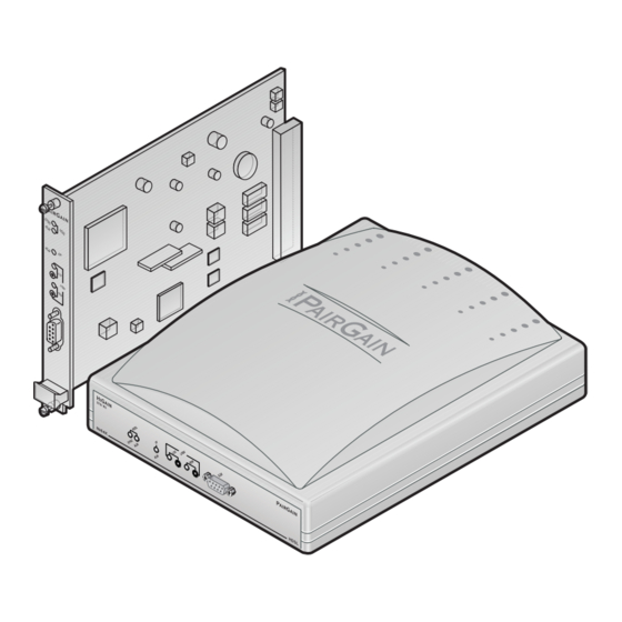
- Page 1 LOBAL CCESS -ETSI RS HDSL L ELECTABLE INE AND ESKTOP NITS Model List Number Part Number UTU-712 150-1422-12 ETU-762 150-1432-12 ECHNOLOGIES NGINEERING ERVICES ECHNICAL RACTICE ™700-712-100-01N¨ 700-712-100-01 ECTION...
- Page 2 PairGain and HiGain are registered trademarks and HiGain-ETSI is a trademark of PairGain Technologies, Inc. Information contained in this document is company private to PairGain Technologies, Inc., and shall not be modified, used, copied, reproduced or disclosed in whole or in part without the written consent of PairGain.
-
Page 3: Table Of Contents
700-712-100-01, Revision 01 Table of Contents ABLE OF ONTENTS Overview ____________________________________________________________________________ 1 Rate Selectable HDSL Unit Firmware....................1 EMU Firmware Compatibility ......................2 Application Interface..........................2 HDSL Technology ..........................3 Transmission Ranges .........................3 Front and Rear Panel Components.....................4 HiGain-ETSI Product Compatibility ....................8 Specifications ________________________________________________________________________ 9 Functional Description _______________________________________________________________ 11 Major Components...........................11 Nx64k Serial Data Port......................12... - Page 4 ECA-801 Connector Adapter (DB25M to DB15F for X.21) ............63 ECA-802 Connector Adapter (DB9M to RJ-45)................64 ECA-804 Connector Adapter (DB9M to Four-Position Terminal Block) ........65 PairGain Regional Sales Offices ________________________________________________________ 66 Product Support _____________________________________________________________________ 67 Technical Support..........................67 Warranty ............................
- Page 5 700-712-100-01, Revision 01 List of Figures IST OF IGURES Figure 1. Transport of Customer Video Service to an Nx64k Serial Network ..........2 Figure 2. UTU-712 Line Unit Front Panel .......................4 Figure 3. ETU-762 Desktop Unit Front Panel....................4 Figure 4. ETU-762 Desktop Unit Rear Panel....................7 Figure 5.
- Page 6 List of Tables 700-712-100-01, Revision 01 Figure 37. History LTU Interface Menu......................50 Figure 38. History NTU Interface Menu ....................... 50 Figure 39. LTU Interface Alarm History Screen ................... 51 Figure 40. History HDSL Span 1 Menu ......................52 Figure 41. 24 Hour History Screen for HDSL Span 1................... 52 Figure 42.
- Page 7 Table 36. ECA-802 DB9M to RJ-45 Connector Adapter Pinouts ..............64 Table 37. ECA-804 DB9M to Four-Position Terminal Block Connector Adapter Pinouts......65 Table 38. PairGain Regional Sales Offices ....................66 Table 39. Minimum Creepage and Clearance Distances................68 UTU-712 and ETU-762 and ETU-752 List 1...
- Page 8 Using This Technical Practice 700-712-100-01, Revision 01 SING ECHNICAL RACTICE Two types of messages, identified by icons, appear in the text. Notes contain information about special circumstances. Cautions indicate the possibility of equipment damage or the possibility of personal injury. Warnungszeichen deuten darauf hin, dass Schaden am Gerät oder eine mögliche Körperverletzung riskiert wird, falls die Warnungen nicht beachtet werden.
-
Page 9: Overview
The NTU is located at the customer site and acts as the slave unit. • UTU is defined by PairGain. These are programmable HDSL line units that can be configured as an LTU (master) or an NTU (slave). The UTU default configuration is NTU (slave). The UTUs do not provide line power to other HDSL units. -
Page 10: Emu Firmware Compatibility
Overview 700-712-100-01, Revision 01 EMU F IRMWARE OMPATIBILITY The EMU-830 Management Unit firmware must be Version 3.30 or later to support rate selectable HDSL units. PPLICATION NTERFACE The application interface is a synchronous serial data port with two modes of operation, Manual and Nx64k Auto. IIn the Nx64k Auto mode, the HDSL payload rate is determined by the frequency of the TT clock received at the Nx64k data port of the LTU-configured unit. -
Page 11: Hdsl Technology
HDSL T ECHNOLOGY HDSL is the core technology for PairGain’s HiGain-ETSI line of LTUs, UTUs, and ETUs. Rate selectable HDSL enables these units to transmit and receive digital data at various rates over various distances on one twisted-pair of copper wire. Both outbound and inbound signals are delivered on the same pair of wires by using echo cancellation techniques. -
Page 12: Front And Rear Panel Components
Overview 700-712-100-01, Revision 01 RONT AND ANEL OMPONENTS The line and desktop unit front panels are shown in Figure 2 Figure 3, respectively. The components on these panels are described in Table 3 on page 5 and in Table 4 on page The ETU-762 desktop unit rear panel is shown in Figure 4 on page 7. -
Page 13: Table 3. Line And Desktop Unit Front Panel Components
700-712-100-01, Revision 01 Overview Table 3. Line and Desktop Unit Front Panel Components Name Function HDSL SYNC LED Displays synchronization state for the HDSL loop. HDSL ALM LED Displays alarm state for the HDSL loop. I/F ALM LED Displays alarm state for the Nx64k serial data port. LOC LPBK LED Displays local (LOC) loopback state. -
Page 14: Table 4. Line And Desktop Unit Front Panel Led Indications
Overview 700-712-100-01, Revision 01 Table 4 defines the system states indicated by the front panel LEDs. When power is applied to the unit, one of the LEDs listed in Table 4 will always be on. Table 4. Line and Desktop Unit Front Panel LED Indications Mode Description HDSL SYNC LED... -
Page 15: Figure 4. Etu-762 Desktop Unit Rear Panel
700-712-100-01, Revision 01 Overview Figure 4. ETU-762 Desktop Unit Rear Panel Table 5. ETU-762 Desktop Unit Rear-Panel Components Item Description D25F data port connector Connects Nx64k data circuits to the enclosure. See Table 33 on page 61 for the D25F data port connector pinouts. -
Page 16: Higain-Etsi Product Compatibility
Overview 700-712-100-01, Revision 01 -ETSI P RODUCT OMPATIBILITY The line and desktop units are compatible with the PairGain HiGain-ETSI products listed in Table Table 6. HiGain-ETSI Product Compatibility Model Description Part Number Rate Selectable HDSL Units UTU-702 Rate Selectable HDSL Line Unit, 64 to 2048 kbps HDSL Line Rate... -
Page 17: Specifications
700-712-100-01, Revision 01 Specifications PECIFICATIONS HDSL Interface Line Code 2B1Q Line Rate (selectable in increments of 64 kbps) Up to 768 kbps Protection K.20, K.21 Compliance TS 101 135 Transmission Ranges (± 200 m): Transmission Ranges with ETSI Noise Transmission Ranges with No Noise 0.4 mm (26 AWG) 0.51 mm (24 AWG) 0.4 mm (26 AWG) - Page 18 Specifications 700-712-100-01, Revision 01 Alarms Can be individually set to Disabled, Minor, or Major (major alarms actuate the UTU-712 alarm relay) Serial Dataport Interface Loss of Clock (LOC) External Clock Loss of Clock (LOC) HDSL Margin, programmable threshold (MAR) Errored Seconds, programmable threshold (ES) Loss of Sync Word (LOSW) History HDSL Interface...
-
Page 19: Functional Description
700-712-100-01, Revision 01 Functional Description UNCTIONAL ESCRIPTION This section provides a functional description of the line and desktop units, including major components, single-pair application mode, alarms, and testing (including monitoring and loopbacks). AJOR OMPONENTS The major components of the line and desktop units include: •... -
Page 20: Nx64K Serial Data Port
(referred to as interface type). The appropriate interface type is configured as described in “System Configuration” page 22. PairGain offers V.35 and X.21 connector adapters (ECA-800 and ECA-801, respectively) to convert the D25F data port connector on the shelves and enclosures to standard V.35 (M34F) and X.21 (D15F) connectors (see “Reference Information”... -
Page 21: Processor
700-712-100-01, Revision 01 Functional Description Timing for the signals transmitted over the HDSL link is nominally derived from the selected primary timing source. In case of failure of the primary timing source, the system utilizes the internal 2.048 MHz oscillator as the backup timing source. -
Page 22: On-Board Power Supply Modules
Functional Description 700-712-100-01, Revision 01 On-Board Power Supply Modules • The UTU-712 line unit has an on-board DC-to-DC power supply module. • The ETU-762 desktop unit has an on-board AC-to-DC power supply module. • A shelf-mounted UTU-712 receives power from a local source of -36 Vdc to -72 Vdc or from the EAC-830 In-Shelf Power Supply. -
Page 23: Hot Swapping
700-712-100-01, Revision 01 Functional Description Other applications for single-pair rate selectable HDSL units include those where deployment of additional subscriber lines is limited by available two-pair HDSL spans. Using two single-pair rate selectable HDSL units on each two-pair span can double the number of subscribers. WAPPING UTUs can be inserted and removed from any compatible shelf or enclosure with the power turned on. -
Page 24: Loopbacks
Functional Description 700-712-100-01, Revision 01 Table 8. HDSL Transmission and Application Interface Alarms Alarm Description HDSL Alarms HDSL alarms (loop-specific) include: Loss of Sync Word The unit cannot receive data over the given HDSL loop. (LOSW) Margin (MAR) The HDSL noise margin of the loop has fallen below the set threshold. Errored HDSL Second (ES) The number of HDSL ES has exceeded the threshold set to give advance warning that HDSL performance is deteriorating. -
Page 25: Figure 10. Loopback Operations
700-712-100-01, Revision 01 Functional Description LTU Interface NTU Interface Single-pair HDSL loop HDSL HDSL Nx64k Nx64k Figure 10. Loopback Operations Table 9. Loopbacks Selected at Front Panel Pushbutons and Console Screens Loopback Description The two loopbacks that follow can be selected from the LOC and REM front-panel pushbuttons, the console screens, the Local Loopback (LL)/Remote Loopback (RL) control lines at the DTE, or the management unit interface. -
Page 26: Ber Testing
Functional Description 700-712-100-01, Revision 01 Table 10 summarizes the equivalent loopbacks for two different activation methods: • LTU and NTU LOC and REM buttons • Console screen Test menus (see “Testing” page 57 for loopback operation from the Test menus). Table 10. -
Page 27: Inspection, Safety, And Equipment Repair
NSPECTION Open the line or desktop unit shipping carton and inspect the contents for signs of damage. If the equipment was damaged in transit, immediately report the extent of the damage to the transportation company and to PairGain Technologies (see “Technical Support”... -
Page 28: Installation And Startup
Installation and Startup 700-712-100-01, Revision 01 NSTALLATION AND TARTUP This section describes the installation and startup procedures for the line and desktop units. UTU-712 L NSTALLATION Perform the following steps to install the UTU-712 line unit. The chassis ground of the shelf or remote enclosure receiving these units must be connected to earth ground for protection of the equipment and for safety of personnel. -
Page 29: Etu-762 Desktop Unit Installation
700-712-100-01, Revision 01 Installation and Startup The line and desktop units will reset and their LEDs will sequence through the startup cycle following any change to the Local Unit Role option. If necessary, log on again by pressing the 63$&(%$5 several times. -
Page 30: System Configuration
System Configuration 700-712-100-01, Revision 01 YSTEM ONFIGURATION Each line unit provides a system-wide view of the entire HDSL circuit, including the remote unit. After establishing communication with the remote line card, provisioning information can be set and performance can be monitored from the local unit. If the HDSL link is down, the only parameters that can be changed are those on the local line unit. -
Page 31: Modem Connection
700-712-100-01, Revision 01 System Configuration To connect and configure a maintenance terminal: Connect a serial cable from the maintenance terminal 9-pin COM port to the line or desktop unit console port connector (Figure 13). Ensure the Data Terminal Ready (DTR) signal from the terminal is connected as the HDSL card will not communicate without it. -
Page 32: Logging On
System Configuration 700-712-100-01, Revision 01 OGGING To log on to the maintenance terminal console screen: Press the 63$&(%$5 several times to display the Logon Password screen (Figure 14). Figure 14. Logon Password Screen (17(5 key is the factory default password. If you establish a different password, you must type the new password (single word, no spaces, up to eight characters) on a subsequent log on. -
Page 33: Console Screen Menu Structure
700-712-100-01, Revision 01 System Configuration ONSOLE CREEN TRUCTURE The following sections describe the structure of the console screen and how to read and navigate through its displays and menus. The structure of the console screen displays and drop-down menus is shown in Figure 16. -
Page 34: Table 11. Console Screen Menus
System Configuration 700-712-100-01, Revision 01 Table 11 describes the drop-down menus selected from the console screen. Table 11. Console Screen Menus Menu Name Function Described in this section Main Display the Main console screen to: “Main Console Screen” page 43 •... -
Page 35: Reading And Navigating Menus
700-712-100-01, Revision 01 System Configuration EADING AND AVIGATING ENUS The menu and status bars appear on all console screens. The information on the rest of the screen varies depending on the function of the menu or screen. The menu bar displays the name of each menu. Choosing Monitor, History, or Config from the menu bar drops down a menu of available options. -
Page 36: Table 13. Console Screen Navigation Keys
System Configuration 700-712-100-01, Revision 01 Use the keys described in Table 13 to navigate the console screen and its menus: Table 13. Console Screen Navigation Keys Press this Key To Perform this Function Alpha-numeric keys Type the underlined or highlighted letter to select and execute a menu item. For example on the Main console menu, type &... -
Page 37: Config Menu Options
700-712-100-01, Revision 01 System Configuration Config Menu Options Type & at the console screen (Figure to display the Config menu (Figure 18). Table 14 lists the Config menu options and the order of system configuration. Figure 18. Console Screen Config Menu Table 14. -
Page 38: Configure Terminal Settings
System Configuration 700-712-100-01, Revision 01 Configure Terminal Settings The console screens use line drawing characters to enclose menu selections and dialog boxes. Because not all maintenance terminals and terminal emulation programs adhere consistently to the VT100 standard, the HDSL card allows you to adjust the display for best results on a given terminal. -
Page 39: Configure Date And Time
700-712-100-01, Revision 01 System Configuration Configure Date and Time Type at the Config drop-down menu to display the Config Date and Time menu (Figure 20). Figure 20. Config Date and Time Menu Type the date in DD/MM/YY format, then press (17(5 Type the time in HH : MM format (24-hour clock), then press (17(5... -
Page 40: Change Password
Retype the new password (up to eight characters) to confirm its accuracy. (17(5 When changing the default password ( ), save the new password in a secure place. A password cannot be recovered if it is forgotten. Contact a PairGain Regional Sales Office if assistance is needed (see page 66). -
Page 41: Configure Circuit Id
700-712-100-01, Revision 01 System Configuration Configure Circuit ID The circuit ID appears on the status line of each console screen. Choose a unique circuit ID for each HDSL card. Type & at the Config drop-down menu to display the Config Circuit ID menu (Figure 22). -
Page 42: Configure System Settings
System Configuration 700-712-100-01, Revision 01 Configure System Settings Use the System Settings menu to select and configure system-wide operating parameters. Configure system settings as follows: Type at the Config drop-down menu to display the Config System Settings menu. Figure 23 shows the Config System Settings menu for the UTU-712 and ETU-762. -
Page 43: Table 15. Fields And Options In Config System Settings Menu
700-712-100-01, Revision 01 System Configuration Table 15. Fields and Options in Config System Settings Menu Field and Options Description Application Mode SINGLE System uses a single-pair of twisted copper wire to transport data. For more information, see “Single-Pair Rate Selectable Applications” on page HDSL Rate Mode Selects the mode with which the HDSL payload rate will be determined. -
Page 44: Configure Ltu And Ntu Interfaces
System Configuration 700-712-100-01, Revision 01 Configure LTU and NTU Interfaces Select and configure the LTU- and NTU-related operating parameters as follows: Type one of the following at the Config drop-down menu to display the Config LTU or NTU Interface menu: •... -
Page 45: Table 16. Fields And Options In Config Ltu And Config Ntu Interface Menus
700-712-100-01, Revision 01 System Configuration Do the following for each interface option to be changed. Table 16 describes the fields and options displayed in the Config LTU and Config NTU Interface menus. • Use the ↑ ↑ ↑ ↑ or the ↓... -
Page 46: Configure Alarms
System Configuration 700-712-100-01, Revision 01 Configure Alarms Use the Config Alarms menu to configure LTU and NTU Interface alarm parameters and the HDSL span alarm parameters. When setting alarm parameters for LTUs and NTUs, keep the following rules in mind: •... -
Page 47: Figure 27. Config Alarms Ltu Interface Menu
700-712-100-01, Revision 01 System Configuration Alarms for LTU and NTU Interface Type one of the following at the Config Alarms drop-down menu to display the Config Alarms LTU or Config Alarms NTU Interface menu: • for the Config Alarms LTU Interface menu (Figure •... -
Page 48: Figure 29. Config Alarms Hdsl Span 1 Menu
System Configuration 700-712-100-01, Revision 01 Table 18. Fields in Config Alarms LTU and Config Alarms NTU Interface Menus Field Description Loss of Clock (LOC) Selects whether the alarm is disabled (DIS), or enabled and reported as a Minor (MIN) or Major (MAJ) alarm when the LOC condition occurs. -
Page 49: Set To Factory Defaults
Not supported. These units do not supply power to other units. ET TO ACTORY EFAULTS Set to Factory Dflts is the screen from which all operating options can be reset to the PairGain factory defaults. Type at the Config drop-down menu to display the Set to Factory Dflts screen (Figure 30). -
Page 50: Logging Off
System Configuration 700-712-100-01, Revision 01 Do one of the following: • Type to keep the current settings. • < Type to reset values to factory defaults. The system resets and both LTU and NTU units go through their respective synchronization processes. If loops are down or are in update mode while Set to Factory Dflts is enabled, only the local unit will restart. -
Page 51: Viewing Status
700-712-100-01, Revision 01 Viewing Status IEWING TATUS The following sections describe the screens that display status and system information, such as current alarm status, performance history, product, and configuration information. View status using a maintenance terminal or PC running a terminal emulation program connected to the V.24 (RS-232) console port. -
Page 52: Table 22. Fields In Main Console Screen
Viewing Status 700-712-100-01, Revision 01 Table 22 describes the fields displayed on the Main console screen. Table 22. Fields in Main Console Screen Field Description Circuit Configuration V.35/V.36/X.21/RS-530 Indicates the interface standard for Nx64k serial data port. Indicates the data rate (n) mapped to the Nx64k interface. Timing Indicates the primary source the LTU/NTU uses for clock synchronization: Internal oscillator. -
Page 53: Monitor Menu
700-712-100-01, Revision 01 Viewing Status ONITOR The Monitor menu contains the following options: • LTU Interface screen that displays signal activity at the LTU serial data port. • NTU Interface screen that displays signal activity at the NTU serial data port. •... -
Page 54: Monitor Ltu Interface Screen
Viewing Status 700-712-100-01, Revision 01 Monitor LTU Interface Screen The Monitor LTU Interface screen permits viewing of signaling activity at the LTU serial data port. At the Monitor menu (Figure 32), type to display the Monitor LTU Interface screen (Figure 33). -
Page 55: Monitor Ntu Interface Screen
700-712-100-01, Revision 01 Viewing Status Monitor NTU Interface Screen The Monitor NTU Interface screen permits viewing of signaling activity at the NTU serial data port. At the Monitor menu (Figure 32), type to display the Monitor NTU Interface screen (Figure 34). -
Page 56: Monitor Hdsl Span 1 Screen
Viewing Status 700-712-100-01, Revision 01 Monitor HDSL Span 1 Screen The Monitor HDSL Span 1 screen permits viewing of the 24-hour error counts for the HDSL span. A span is defined as the link between two HDSL units (that is, from an LTU to an NTU) which, in this case, is comprised of a single loop (that is, one twisted-copper pair). -
Page 57: History Menu
700-712-100-01, Revision 01 Viewing Status ISTORY The History menu contains the following status screens: • LTU/NTU Interfaces that display alarm performance history for the LTU and NTU interface. • HDSL Span that displays 24-hour, 7-day, and alarm performance history for the HDSL span. The History menu also provides the option to clear the 24-hour, 7-day, and alarm history screens. -
Page 58: History Ltu And Ntu Interface Screens
Viewing Status 700-712-100-01, Revision 01 History LTU and NTU Interface Screens At the History menu (Figure 36), type to select the History LTU Interface menu (Figure 37). Figure 37. History LTU Interface Menu At the History menu (Figure 36), type to select the History NTU Interface menu (Figure 38). -
Page 59: Figure 39. Ltu Interface Alarm History Screen
700-712-100-01, Revision 01 Viewing Status Only the Alarm History screen is available for the LTU and NTU interfaces. The 24 Hour and 7 Day History screens, as well as the Alarm History screen, are available for HDSL Span 1. LTU and NTU Interface Alarm History Screens At the History LTU or History NTU Interface menu, type the key to select an Alarm History status screen. -
Page 60: Hdsl Span Performance History Screens
Viewing Status 700-712-100-01, Revision 01 HDSL Span Performance History Screens At the History menu (Figure 36), type to select the History HDSL Span 1 menu (Figure 40). Figure 40. History HDSL Span 1 Menu The History HDSL Span 1 menu contains three viewing options: •... -
Page 61: Figure 42. 7 Day History Status Screen For Hdsl Span 1
700-712-100-01, Revision 01 Viewing Status The 24 Hour History screen for HDSL Span 1 contains three columns of data that show (from left to right) the: • Starting time of each 15-minute interval. • Number of ES/UAS at the LTU end of the HDSL span (LTU-1) for each interval. A dash (-) represents a count of zero. -
Page 62: Figure 43. Alarm History Status Screen For Hdsl Span 1
Viewing Status 700-712-100-01, Revision 01 HDSL Span 1 Alarm History Screens At the History HDSL Span 1 menu (Figure 40), type to select the Alarm History status screen for HDSL Span 1 (Figure 43). Figure 43. Alarm History Status Screen for HDSL Span 1 Table 26 describes the four columns of data contained in each HDSL Span Alarm History screen. -
Page 63: Clear History Screens
700-712-100-01, Revision 01 Viewing Status Clear History Screens Use the following options to clear the 24 Hour, 7 Day, or Alarm History status screens: • Clr 24 Hr Hist: clears all of the 24-hour history error counters • Clr 7 Day Hist: clears all of the 7-day history error counters •... -
Page 64: Table 27. Inventory Screen Data
Days Op Displays the number of days the LTU, NTU, and any doubler units have been in operation. SW Part # Displays the PairGain part number of the firmware. Chksum Displays the checksum of the LTU, NTU, and doubler unit proms. -
Page 65: Testing
700-712-100-01, Revision 01 Testing ESTING From the main console screen (Figure 31), type to display the Test menu from which you can set and run loopback and BER tests (Figure 45). See page 16 for a description of loopbacks. Figure 45. Test Menu Screen Table 28 on page 58 lists the Test menu options. -
Page 66: Table 28. Test Menu Options
Testing 700-712-100-01, Revision 01 Table 28. Test Menu Options Operating Option Default Setting Network Diagram Shows the loopback position and direction when the loopback is enabled and active. Lpbk Dir Selects one of three loopback direction modes: No loopbacks are active. NETWORK The loopback selected in Loopback Position is directed toward the network equipment connected to the LTU. -
Page 67: Firmware Download Utility
700-712-100-01, Revision 01 Firmware Download Utility IRMWARE OWNLOAD TILITY The Firmware Download Utility is a separate program and is not available from the console screen menus. This section describes the ETSI Firmware Download utility and how to use it to upgrade the line unit firmware. The ETSI Firmware Download utility is a program you can run on a PC to download new firmware to the LTU or NTU by connecting a standard RS-232 interface cable to the unit front panel V.24 console port. -
Page 68: Table 30. Etsi Firmware User Selectable Download Menu Options
Firmware Download Utility 700-712-100-01, Revision 01 Initiate the Download and Navigate the Menus To initiate the download process, go to the DOS prompt and type: dnl. Table 30 describes ETSI Firmware User Selectable Download Menu Options. Table 30. ETSI Firmware User Selectable Download Menu Options Option Description PORT... -
Page 69: Reference Information
700-712-100-01, Revision 01 Reference Information EFERENCE NFORMATION This section lists the pinouts for the ETU-762 rear panel connectors and the ECA-80x connector adapters. ETU-762 C ONNECTOR INOUTS The pinouts for the ETU-762 rear panel connectors are listed in Table 32 Table Table 32. -
Page 70: Eca-800 Connector Adapter (Db25M To M34F For V.35)
Reference Information 700-712-100-01, Revision 01 ECA-800 C (DB25M M34F V.35) ONNECTOR DAPTER The ECA-800 connector adapter (Figure 47) converts the DB25F data port connector on the desktop unit rear panel to a standard V.35 34-pin female connector. Table 34 lists the ECA-800 pinouts. Figure 47. -
Page 71: Eca-801 Connector Adapter (Db25M To Db15F For X.21)
700-712-100-01, Revision 01 Reference Information ECA-801 C (DB25M DB15F X.21) ONNECTOR DAPTER The ECA-801 connector adapter (Figure 48) converts the DB25F data port connector on the desktop unit rear panel to a standard X.21 15-pin female connector. Table 35 lists the ECA-801 pinouts. Figure 48. -
Page 72: Eca-802 Connector Adapter (Db9M To Rj-45)
Reference Information 700-712-100-01, Revision 01 ECA-802 C (DB9M RJ-45) ONNECTOR DAPTER The ECA-802 connector adapter (Figure 49) converts the DB9F HDSL line connector on the desktop unit rear panel to an RJ-45 modular style connector. Table 36 lists the ECA-802 pinouts. Figure 49. -
Page 73: Eca-804 Connector Adapter (Db9M To Four-Position Terminal Block)
700-712-100-01, Revision 01 Reference Information ECA-804 C (DB9M ONNECTOR DAPTER OSITION ERMINAL LOCK The ECA-804 connector adapter (Figure 50) converts the DB9F HDSL line connector on the desktop unit rear panel to a four-position terminal-block style connector. Table 37 lists the ECA-804 pinouts. Figure 50. -
Page 74: Pairgain Regional Sales Offices
+86.20.83873011 +86.20.83873011 8:30AM to 5:00PM RDERING ROCEDURE Orders may be placed through PairGain regional sales offices by telephone, fax or, mail. A fax is preferred. When placing an order, please provide the following information: • Customer purchase order number; •... -
Page 75: Product Support
Do not try to repair the unit. If it fails, replace it with another unit and return the faulty unit to PairGain for repair. Any modifications of the unit by anyone other than an authorized PairGain representative voids the warranty. -
Page 76: Internet Access
PairGain FTP Site at ftp.pairgain.com/etsi and the Customer Site portion of the PairGain Web site at www.pairgain.com. A password is required to download from either site. If you do not have a password, contact your PairGain sales representative. -
Page 77: Abbreviations
700-712-100-01, Revision 01 Abbreviations BBREVIATIONS Alarm Indication Signal Local Loopback Alarm Local ANSI American National Standards Institute Loss of Clock American Wire Gage LOSW Loss of Sync Word Bit Error Rate LPBK Loopback Centigrade Line Termination Unit Communication M34F M-type 34-pin Female Connector Cyclic Redundancy Check Margin Clear To Send... - Page 80 Corporate Office 14402 Franklin Avenue Tustin, CA 92780 Tel: (714) 832-9922 Fax: (714) 832-9924 For Technical Assistance: (800) 638-0031...