Table of Contents
Advertisement
Quick Links
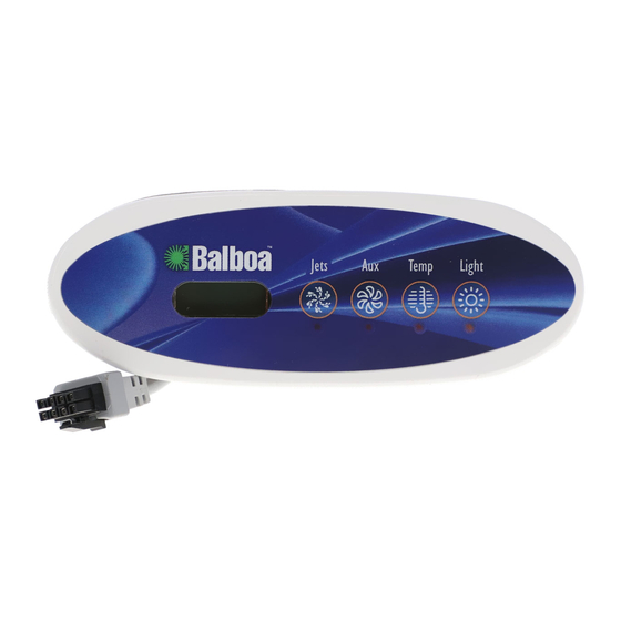
EL/GL Series - Mach 3
ML240 User Guide
Note regarding EL and GL systems: Mach 3 EL and GL systems function
identically, but conform to different International requirements. This
user guide will refer to EL systems for the sake of simplicity, but the
information given applies to both EL and GL products.
900854
Jets
Jets
Aux
Aux
Temp
Temp
Light
Light
Jets
Jets
Aux
Aux
Temp
Temp
Light
Light
Advertisement
Table of Contents

Summary of Contents for Balboa Instruments ML240
- Page 1 EL/GL Series - Mach 3 ML240 User Guide Jets Jets Temp Temp Light Light Jets Jets Temp Temp Light Light Note regarding EL and GL systems: Mach 3 EL and GL systems function identically, but conform to different International requirements. This user guide will refer to EL systems for the sake of simplicity, but the information given applies to both EL and GL products.
-
Page 3: Table Of Contents
EL/GL SERIES (Mach 3) CONTROL WITH ML240 PANEL The ML240 panel can be used as a main panel The pump responsible for heating and filtration (pump 1 with the EL2000 and EL1000 systems, but only as a low on non-circ systems, or the circ pump on circ remote/additional panel for the EL8000 and EL5000 systems) will be referred to simply as the pump. -
Page 4: Temp Set
Standby Mode Temp Set (80°F - 104°F / 26.0°C - 40.0°C) Pressing “Temp” followed by “Aux” or “Jets 2” or The last measured temperature is constantly displayed “Blower” will turn off all spa functions temporarily. This on the LCD. Your spa’s set temperature range may is helpful when changing a filter. -
Page 5: Light
Locking Features Light If this panel is used as the main panel, locking features Some systems are equipped with both a spa light and a will not be available. fiber optic light; however, only one can be accessed by this If this panel is used as a remote or additional panel, it panel. -
Page 6: User Preferences
User Preferences Editing User Preferences There are several aspects of spa operation that you can View the setting. customize using the User Preferences submenu. The left two characters (before the decimal point) tell Press “Temp” then “Jets”, then “Light”. (Each press must you what setting you’re viewing or editing, the right most be within 3 seconds of the previous press.) At this point, character (after the decimal point) tells you the value of... -
Page 7: Periodic Reminder Messages
Periodic Reminder Messages (Press the “Temp” button to reset a displayed reminder.*) Message ** Frequency *** Action Required Every 7 days Test and adjust pH chemical levels per manufacturer’s instructions. Every 7 days Test and adjust sanitizer chemical levels per manufacturer’s instructions. Every 30 days Remove, clean, and reinstall filter per manufacturer’s instructions. -
Page 8: Diagnostic Messages
Diagnostic Messages Message Meaning Action Required No message on display. The control panel will be disabled until power returns. Power has been cut off to the spa. Time of day will be preserved for 30 days with a battery back-up on EL8000 and EL5000 systems. EL1000 and some EL2000 systems reset the time of day on each power-up. - Page 9 Diagnostic Messages (continued) Message Meaning Action Required Temperature unknown. After the pump has been running for 1 minute, the temperature will be displayed. Standby Mode has been activated by pressing Press any button, except “Jets”, to leave Standby Mode a button combination on the user panel. and return to normal operation.
-
Page 10: Optional Auxiliary Panels
Optional Auxiliary Panels Note: Below is a partial list of optional auxiliary panels and their basic functions. Please contact for local dealer for a complete list of options that will work with your spa. Jets 1 Jets 1 Jets 1 Jets 1 Jets 2 Blower... -
Page 11: Basic Installation Guidelines
Warning! Qualified technician required for service and installation. Basic Installation and Configuration Guidelines for Mach 3 CSA Compliance/Conformité EL-Series Spa Controllers. Caution: • Test the ground fault circuit interrupter before each use of Use minimum 6AWG copper conductors only. the spa. Torque field connections between 21 and 23 in lbs. - Page 12 Warning! Shock Hazard! No User Serviceable Parts. Do not attempt service of this control system. Contact your dealer or service organization for assistance. Follow all owner’s manual power connection instructions. Installation must be performed by a licensed electrician and all grounding connections must be properly installed.


