Cisco Carrier Routing System CRS-1 Installation Manual
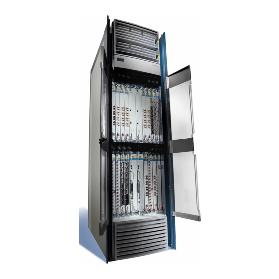
Carrier routing system 4-slot line card chassis
Hide thumbs
Also See for Carrier Routing System Cisco CRS-1:
- Administration manual (436 pages) ,
- Getting started manual (289 pages) ,
- Troubleshooting manual (264 pages)
Table of Contents
Advertisement
Quick Links
Advertisement
Table of Contents

Related Manuals for Cisco Carrier Routing System Cisco CRS-1


Summary of Contents for Cisco Carrier Routing System Cisco CRS-1
-
Page 1: Installation Guide
Cisco CRS Carrier Routing System 4-Slot Line Card Chassis Installation Guide July 2011 Americas Headquarters Cisco Systems, Inc. 170 West Tasman Drive San Jose, CA 95134-1706 http://www.cisco.com Tel: 408 526-4000 800 553-NETS (6387) Fax: 408 527-0883 Text Part Number: OL-10971-10... - Page 2 Modifications to this product not authorized by Cisco Systems, Inc. could void the FCC approval and negate your authority to operate the product. The Cisco implementation of TCP header compression is an adaptation of a program developed by the University of California, Berkeley (UCB) as part of UCB’s public domain version of the UNIX operating system.
-
Page 3: Table Of Contents
Preface Objective Audience Document Organization Document Conventions Related Documentation Changes to This Document Obtaining Documentation and Submitting a Service Request Overview C H A P T E R Chassis Overview Chassis Components Chassis Slot Numbers Chassis Cable Management Chassis Cooling System Chassis Power System Safety Guidelines Preventing Electrostatic Discharge... -
Page 4: Removing A Pillow Block
Contents Removing a DC Power Shelf Installing an AC Power Shelf Removing an AC Power Shelf Installing a Power Supply Removing a Power Supply Installing and Removing Air Circulation Components C H A P T E R About Line Card Chassis Airflow How to Install or Remove Air Circulation Components Installing a Fan Tray Removing a Fan Tray... - Page 5 Installing an RP or PRP Card Removing an RP or PRP Card Verifying the Installation of an RP or PRP Card How to Install or Remove an MSC, FP, or LSP Installing an MSC, FP, or LSP Removing an MSC, FP, or LSP Verifying the Installation of an MSC, FP, or LSP How to Install or Remove a Physical Layer Interface Module Installing a PLIM...
- Page 6 Contents Cisco CRS Carrier Routing System 4-Slot Line Card Chassis Installation Guide OL-10971-10...
-
Page 7: Objective
Preface This preface explains the objectives, intended audience, and organization of Cisco CRS Carrier Routing System 4-Slot Line Card Chassis Installation Guide and describes the conventions that convey instructions and other information. The preface contains the following sections: Objective, page vii •... -
Page 8: Document Conventions
Chapter 1, “Overview,” • components. This chapter also provides the recommended sequence of tasks for installing all the major components of the Cisco CRS 4-slot line card chassis. Chapter 2, “Installing and Removing Power Components,” • power components in the line card chassis, including the AC and DC power shelves power supplies, and alarm module. -
Page 9: Related Documentation
Preface Timesaver Means the described action saves time. You can save time by performing the action described in the paragraph. Means reader be careful. You are capable of doing something that might result in equipment damage or Caution loss of data. This warning symbol means danger. -
Page 10: Changes To This Document
Changes to This Document Table 1-1 lists the technical changes made to this document since it was first printed. Table 1-1 Revision OL-10971-10 OL-10971-09 OL-10971-08 OL-10971-07 OL-10971-06 OL-10971-05 OL-10971-04 OL-10971-03 OL-10971-02 OL-10971-01 Cisco CRS Carrier Routing System 4-Slot Line Card Chassis Installation Guide Changes to This Document Date Change Summary... -
Page 11: Obtaining Documentation And Submitting A Service Request
Preface Obtaining Documentation and Submitting a Service Request For information on obtaining documentation, submitting a service request, and gathering additional information, see the monthly What’s New in Cisco Product Documentation, which also lists all new and revised Cisco technical documentation, at: http://www.cisco.com/en/US/docs/general/whatsnew/whatsnew.html Subscribe to the What’s New in Cisco Product Documentation as a Really Simple Syndication (RSS) feed and set content to be delivered directly to your desktop using a reader application. - Page 12 Preface Cisco CRS Carrier Routing System 4-Slot Line Card Chassis Installation Guide OL-10971-10...
-
Page 13: Chassis Overview
Overview This chapter introduces the Cisco CRS Carrier Routing System 4-Slot Line Card Chassis at the highest level. It contains illustrations of the front and back of the chassis, complete with callouts to each hardware component. For details on each subsystem discussed in this chapter, see Cisco CRS Carrier Routing System 4-Slot Line Card Chassis System Description. -
Page 14: Chapter 1 Overview
Chassis Components Chassis Components This section lists the main components of a Cisco CRS 4-slot line card chassis. It primarily identifies the components that are considered field-replaceable units (FRUs), but where additional detail is useful this section identifies subassemblies that are not field replaceable. Figure 1-1 rear (SFC) sides. -
Page 15: Fan Tray
Chapter 1 Overview Figure 1-2 1 Fan tray 2 AC power plug connectors The Cisco CRS 4-slot line card chassis contains the following components: As many as four MSCs, FPs, or LSPs and four PLIMs. The line card and PLIM are an associated •... - Page 16 Chassis Components A chassis midplane that connects line cards to their associated PLIMs. The midplane design allows • a line card to be removed from the chassis without having to disconnect the cables that are attached to the associated PLIM. The midplane distributes power, connects the line cards to the switch fabric cards, and provides control plane interconnections.
-
Page 17: Chassis Slot Numbers
Chapter 1 Overview Chassis Slot Numbers This section identifies the location and slot numbers for major cards and modules (primarily the field-replaceable units) that plug into the Cisco CRS 4-slot line card chassis. Figure 1-3 shows the slot numbering on the front (PLIM) side of the Cisco CRS 4-slot line card chassis. Figure 1-3 1 MSC slot 0 2 MSC slot 1... - Page 18 Chassis Slot Numbers Figure 1-4 1 Fan tray (FT0) 2 Switch fabric card slot (SM3) 3 Switch fabric card slot (SM2) As shown in Figure Fan tray • Card cage, including four reduced-height SFC slots (SM0 to SM3, right to left) •...
-
Page 19: Chassis Cable Management
Chapter 1 Overview Chassis Cable Management The Cisco CRS 4-slot line card chassis has cable management features for the front (PLIM) side of the chassis, just above the card cage. The horizontal cable management trays have a special telescoping feature that allows them to be extended when the chassis is upgraded with higher-density cards. This extension also helps when installing the cables in the chassis. -
Page 20: Chassis Power System
Chassis Power System Figure 1-6 Chassis air inlet Power shelf air inlet Front The Cisco CRS 4-slot line card chassis airflow volumes are as follows: Chassis airflow: Up to 880 cubic feet (24,919 liters) per minute • Power system airflow: Up to 60 cubic feet (1,699 liters) per minute •... -
Page 21: Preventing Electrostatic Discharge
Chapter 1 Overview Review the safety warnings listed in Regulatory Compliance and Safety Information that are applicable Note to your router before installing, configuring, or troubleshooting any installed card. • Keep the work area clear and dust-free during and after installation. Do not allow dirt or debris to enter into any laser-based components. -
Page 22: Recommended Chassis Installation Task Sequence
Recommended Chassis Installation Task Sequence Recommended Chassis Installation Task Sequence This section provides the recommended task sequence for installing a new Cisco CRS 4-slot line card chassis. If your system was shipped with AC power, remove the four AC power cords from the box, and do the Step 1 following: Insert all four power cords into the AC power source. - Page 23 Chapter 1 Overview Table 1-1 CRS Compatibility Matrix Switch Fabric RP/DRP CRS-4-FC/S RP-A (CRS-4-RP), (40G) DRP-B (CRS-DRP-B) RP-A (CRS-4-RP), DRP-B (CRS-DRP-B) CRS-4-FC140/S RP-A (CRS-4-RP), (140G) DRP-B (CRS-DRP-B) RP-A (CRS-4-RP), DRP-B (CRS-DRP-B) (CRS-4-PRP-6G, CRS-4-PRP-12G) (CRS-4-PRP-6G, CRS-4-PRP-12G) PRP (CRS-4-PRP-6G, CRS-4-PRP-12G) OL-10971-10 MSC/FP/LSP PLIMS CRS-MSC-B 1OC768-DPSK/C...
- Page 24 Chapter 1 Overview CRS Hardware Compatibility Cisco CRS Carrier Routing System 4-Slot Line Card Chassis Installation Guide 1-12 OL-10971-10...
-
Page 25: About Installing And Removing The Power Components
Installing and Removing Power Components This chapter provides instructions on how to install and remove the Cisco CRS Carrier Routing System 4-Slot Line Card Chassis power components. This chapter presents the following topics: About Installing and Removing the Power Components, page 2-1 •... -
Page 26: Supplemental Unit Bonding And Grounding Guidelines
About Installing and Removing the Power Components A Cisco router must be operated with all its power modules installed at all times for electromagnetic Caution compatibility (EMC). The Cisco CRS 4-slot line card chassis requires that at least the power shelves and their components be installed to operate properly. -
Page 27: Nebs Bonding And Grounding
Cisco Systems; they are available from any commercial hardware vendor. A commensurately rated ground wire. The actual wire diameter and length depend on your router • location and site environment. This wire is not available from Cisco Systems; it is available from any commercial cable vendor. OL-10971-10... -
Page 28: Ac Power Supply Cord Illustrations And Plug Types
About Installing and Removing the Power Components The DC return of this system should remain isolated from the system frame and chassis (DC-I: Isolated Note DC Return). AC Power Supply Cord Illustrations and Plug Types This section contains the AC power cord illustrations and a table of power plug types for the Cisco CRS Carrier Routing System 4-Slot Line Card Chassis for Australia (AU), European (EU), Italy (IT), United Kingdom (UK), United States (USA), and Japan. - Page 29 Chapter 2 Installing and Removing Power Components Figure 2-3 Figure 2-4 Plug: (CEI 23-50) Figure 2-5 13A replaceable fuse OL-10971-10 CAB-CRS4AC-EU Cordset rating: 16 A, 250 V Length: 14 ft 0 in. (4.26 m) Plug: CEE 7/7 CAB-CRS4AC-IT Cordset rating: 16 A, 250 V Length: 14 ft 0 in.
-
Page 30: Powering The Chassis Up Or Down
About Installing and Removing the Power Components Figure 2-6 Plug: NEMA L6-20 Powering the Chassis Up or Down The chassis does not have a single enable switch that powers the entire chassis and all its components up and down. (These switches are called enable switches because they enable the power supplies to produce output voltage and power). -
Page 31: Dc Power Systems On The Cisco Crs 4-Slot Router
Chapter 2 Installing and Removing Power Components Figure 2-7 For an illustration of the DC power enable switches, see All power cords must be unplugged from wall power to fully remove power from the chassis. Note DC Power Systems on the Cisco CRS 4-Slot Router The Cisco CRS 4-slot line card chassis DC power shelf consists of two major components, as shown in Figure 2-8:... - Page 32 Chapter 2 Installing and Removing Power Components DC Power Systems on the Cisco CRS 4-Slot Router Figure 2-8 DC Power Shelf: DC Power Input Shelf and DC Power Input Module (PIM) Front orientation Rear orientation 1 DC power input shelf 2 Power input module (PIM) When installing the DC power shelf, these two components are mated to create the complete DC power shelf (see the...
-
Page 33: Dc Power Shelf Guidelines
(four pairs) for each power shelf, plus the grounding wire. The length of the wires depends on the router’s location. These wires are not available from Cisco Systems; they are available from any commercial vendor. •... -
Page 34: Wiring Block On The Pim
DC Power Systems on the Cisco CRS 4-Slot Router Table 2-2 Nominal input voltage Input line current Inrush current When wiring the DC power shelf, be sure to attach the ground wire first. When removing the wiring, be Note sure to remove the ground wire last. The ground wire must be attached with a torque value of 30 in-lb. The power cables should also be attached with a torque value of 30 in-lb. -
Page 35: Input-Power-Present Leds
Chapter 2 Installing and Removing Power Components Input-Power-Present LEDs The DC power Input-Power-Present LEDs provide a visual indication to service personnel that there is voltage present across the input terminal’s connections (see to the service person that there is power present. Note Power should be disconnected before servicing the input power connections. - Page 36 DC Power Systems on the Cisco CRS 4-Slot Router Table 2-3 Note wire. Table 2-3 Wire Gauge for Current Loads Over Copper Wire Lengths DC Current (Amps) 25 Feet 50 Feet 18 AWG 14 AWG 10 A 14 AWG 12 AWG 15 A 14 AWG 10 AWG...
- Page 37 Chapter 2 Installing and Removing Power Components Table 2-4 provides the correlation between wire gauge and the resistance (in Ohms for each 1000 feet of wire) for copper wire. Table 2-4 Wire Gauge (AWG) 0000 AWG 000 AWG 00 AWG 0 AWG 1 AWG 2 AWG...
-
Page 38: Installing A Dc Power Shelf
Installing a DC Power Shelf Installing a DC Power Shelf This section describes how to install a DC power shelf in the Cisco CRS 4-slot line card chassis. The DC power shelf encloses four power supplies and the power distribution connections and wiring. The DC power input shelf is installed in the front of the chassis;... - Page 39 Chapter 2 Installing and Removing Power Components This procedure assumes that the Cisco CRS 4-slot line card chassis is already mounted in a rack with Note sufficient room to access the sides and the bottom of the chassis. Steps To install the DC power shelf, follow these steps: Attach the ESD-preventive wrist strap to your wrist and connect its leash to one of the ESD connection Step 1 sockets on the front (PLIM) side of the chassis or a bare metal surface on the chassis.
- Page 40 Installing a DC Power Shelf Installing the DC Power Input Module From the rear of the chassis, insert the DC power input module (PIM) into the open power bay (see Step 5 Figure 2-13). Note The PIM weighs 6.5 lb (2.9 kg). Figure 2-13 –...
- Page 41 Chapter 2 Installing and Removing Power Components Figure 2-14 Securing the PIM to the DC Power Input Shelf Go to the rear of the chassis. To mate the PIM to the DC power input shelf, push the PIM firmly but Step 8 carefully into the power input shelf.
- Page 42 Installing a DC Power Shelf When wiring the power shelf, be sure to attach the ground wire first. When removing the wiring, Note be sure to remove the ground wire last. The ground wire must be attached with a torque value of 30 in-lb.
- Page 43 Chapter 2 Installing and Removing Power Components The wiring block covers can be oriented to route the wire cabling from the top or the bottom of Note the covers. Installing the DC Power Supplies Step 13 Go to the front of the chassis. Install the four DC power supplies into the power input shelf (see Figure 2-17).
-
Page 44: Removing A Dc Power Shelf
Removing a DC Power Shelf Figure 2-18 1 Chassis air filter 2 Air intake grille Install the inlet grille. See the Step 15 Removing a DC Power Shelf This section describes how to remove a DC power shelf from the Cisco CRS 4-slot line card chassis. The DC power shelf is comprised of both the DC power input shelf and the DC power input module (PIM). -
Page 45: Required Tools And Equipment
Chapter 2 Installing and Removing Power Components Prerequisites Power down the Cisco CRS 4-slot line card chassis (as described in the steps below). Required Tools and Equipment You need the following tools and parts to perform this task: ESD-preventive wrist strap •... -
Page 46: Dc Power Shelf Enable Switches
Removing a DC Power Shelf Figure 2-19 – (RT N) (-4 8V /-6 0V ) – (RT N) (-4 8V /-6 0V ) Remove both wiring block covers (see Step 3 Use a number 1 Phillips screwdriver to loosen the capture screw. Snap off the cover over the wiring block. - Page 47 Chapter 2 Installing and Removing Power Components Figure 2-20 Removing Wiring Block Covers and DC Input Power Cables – (R TN ) (-4 8V /-6 0V ) – (R TN ) (-4 8V /-6 0V ) 1 Power shelf coupling screw With a 5-mm Allen wrench, loosen the power shelf coupling screw (see item 1 in Step 6 allow you to remove the DC power input shelf from the chassis (as described below).
-
Page 48: Installing An Ac Power Shelf
Installing an AC Power Shelf Figure 2-21 Removing the DC Power Input Shelf Remove the DC Power Input Module (PIM) Go to the rear of the chassis. Remove the DC power input module (PIM). Step 10 With a Number 2 Phillips screwdriver, remove the first set of eight screws—six screws in the front of the chassis, two on the outside right and left sides of the chassis (see Remove the additional two screws underneath the chassis (one on the left side, one on the right side) (see... - Page 49 Chapter 2 Installing and Removing Power Components The AC-powered chassis contains a single AC power shelf containing four AC power supplies. Each AC power supply converts input AC power to the –54 VDC used by the Cisco CRS 4-slot line card chassis. The AC power shelf is configured for single-phase AC power supply wiring (two wires + ground), and is safety-rated at 110 to 240 VAC nominal, 50 to 60 Hz (4x) 11A.
-
Page 50: Removing An Ac Power Shelf
Removing an AC Power Shelf Steps To install an AC power shelf, use Step 1 Attach the ESD-preventive wrist strap to your wrist and connect its leash to one of the ESD connection sockets on the front (PLIM) side of the chassis or a bare metal surface on the chassis. Step 2 Remove the air intake grille from the bottom of the chassis. - Page 51 Chapter 2 Installing and Removing Power Components Prior to removing the AC power shelf, to reduce the risk of damage, ensure that the rear panel fasteners Caution are disengaged, the input power cables are disconnected, and the air intake (inlet) grille is removed. Figure 2-23 Prerequisites Before performing this task, you must first remove the air intake grille from the bottom of the chassis,...
-
Page 52: Installing A Power Supply
Installing a Power Supply What to Do Next After performing this task, you may install a replacement power shelf (see the Shelf” section on page page 2-28), and replace any front chassis cosmetic covers. Installing a Power Supply This section describes how to install an AC or DC power supply in the Cisco CRS 4-slot power shelf. The AC power supply converts facility AC power into the DC power necessary to power the cards and modules in the chassis. - Page 53 Chapter 2 Installing and Removing Power Components Steps To install a power supply, follow these steps: Step 1 Attach the ESD-preventive wrist strap to your wrist and connect its leash to one of the ESD connection sockets on the front (PLIM) side of the chassis or a bare metal surface on the chassis. Step 2 Using two hands to support and guide the power supply, slide it partway into the power tray on the front (PLIM) side of the chassis.
-
Page 54: Removing A Power Supply
Removing a Power Supply To prevent damage to the AC or DC power shelf-to-power supply connections, do not use Caution excessive force when seating a power supply to its power shelf. What to Do Next After performing this task, you may connect the power shelf to the power source (see the Installing and Removing the Power Components”... - Page 55 Chapter 2 Installing and Removing Power Components To unseat the power supply from the power shelf connector, unlatch the power supply door grille latch Step 2 and open it completely. See The power supply fans may continue to turn at high speed for a few seconds after they are Note unseated from the power shelf.
- Page 56 Chapter 2 Installing and Removing Power Components Removing a Power Supply Cisco CRS Carrier Routing System 4-Slot Line Card Chassis Installation Guide 2-32 OL-10971-10...
-
Page 57: Chapter 3 Installing And Removing Air Circulation Components
Installing and Removing Air Circulation Components This chapter provides instructions on how to install and replace the Cisco CRS Carrier Routing System 4-Slot Line Card Chassis air circulation components. This chapter presents the following topics: About Line Card Chassis Airflow, page 3-1 •... - Page 58 About Line Card Chassis Airflow Figure 3-1 Chassis air inlet Power shelf air inlet Front A replaceable air filter is located inside the chassis below the PLIM card cage at an angle. In addition, there is a removable air filter on the front of the power tray air intake grille on the front (PLIM) side of the chassis.
-
Page 59: How To Install Or Remove Air Circulation Components
Chapter 3 Installing and Removing Air Circulation Components Figure 3-2 1 Chassis air filter 2 Air intake grille Note We recommend that you check the air filters once a month. Replace a filter when you notice a significant amount of dust. To remain NEBS compliant, the chassis air filter can be replaced only when the fan trays are not running. -
Page 60: Installing A Fan Tray
How to Install or Remove Air Circulation Components Installing a Fan Tray This section describes how to install a fan tray in the Cisco CRS 4-slot line card chassis. For information on the chassis airflow and circulation, see the The fan tray installs into the rear (SFC) side of the chassis (see on regulatory compliance and safety, see Cisco CRS Carrier Routing System Regulatory Compliance and Safety Information. -
Page 61: Removing A Fan Tray
Chapter 3 Installing and Removing Air Circulation Components Required Tools and Equipment You need the following tools and part to perform this task: ESD-preventive wrist strap • Large flat-blade screwdriver • Fan tray (Cisco product number CRS-4-FAN-TR=) • Steps To install a fan tray, follow these steps: Attach the ESD-preventive wrist strap to your wrist and connect its leash to one of the ESD connection Step 1 sockets on the rear (SFC) side of the chassis or a bare metal surface on the chassis. -
Page 62: How To Install Or Remove Air Circulation Components
Chapter 3 Installing and Removing Air Circulation Components How to Install or Remove Air Circulation Components The chassis automatically powers down if the fan tray is unseated from its connector for more than one Caution minute. If you plan on hot swapping the fan tray, have the replacement fan tray readily available and be sure to insert it and seat it against its connector within 45 seconds. -
Page 63: Installing The Chassis Air Filter
Chapter 3 Installing and Removing Air Circulation Components Required Tools and Equipment You need the following tools to perform this task: ESD-preventive wrist strap • Large flat-blade screwdriver • Steps To remove a fan tray, follow these steps: Attach the ESD-preventive wrist strap to your wrist and connect its leash to one of the ESD connection Step 1 sockets on the rear (SFC) side of the chassis or a bare metal surface on the chassis. - Page 64 How to Install or Remove Air Circulation Components Figure 3-5 1 Chassis air filter 2 Air intake grille Prerequisites Before performing this task, you must first remove any chassis front cosmetic covers, the lower chassis air intake grille and power tray air filter cover (see the page 3-10).
-
Page 65: Removing The Chassis Air Filter
Chapter 3 Installing and Removing Air Circulation Components Replace the lower chassis grille: Step 3 Position the grille in front of the air intake slot on the lower front side of the chassis and press it gently into place. Make sure that you align the guide pins on the lower corners of the grille with the guide pin holes on the chassis. -
Page 66: Installing A Power Tray Air Filter
How to Install or Remove Air Circulation Components Prerequisites Before performing this task, you must first remove the lower chassis grille and power tray air filter cover (see the “Installing a Power Tray Air Filter” section on page Never operate the line card chassis without an air filter. Doing so can damage the hardware. Caution Required Tools and Equipment You need the following tools to perform this task:... - Page 67 Chapter 3 Installing and Removing Air Circulation Components Figure 3-7 1 Chassis air filter 2 Air intake grille Prerequisites No prerequisites exist for this task. Never operate the line card chassis without an air filter. Doing so can damage the hardware. Caution Required Tools and Equipment You need the following tools and part to perform this task:...
-
Page 68: Removing A Power Tray Air Filter
How to Install or Remove Air Circulation Components Reinstall the lower chassis grille: Step 4 Position the grille in front of the air intake slot on the lower front side of the chassis and press it gently into place. Make sure that you align the guide pins on the lower corners of the grille with the guide pin holes on the chassis. - Page 69 Chapter 3 Installing and Removing Air Circulation Components Required Tools and Equipment You need the following tools to perform this task: ESD-preventive wrist strap • Medium flat-blade screwdriver • Steps To remove a power tray air filter, follow these steps: Attach the ESD-preventive wrist strap to your wrist and connect its leash to one of the ESD connection Step 1 sockets on the front (PLIM) side of the chassis or a bare metal surface on the chassis.
- Page 70 Chapter 3 Installing and Removing Air Circulation Components How to Install or Remove Air Circulation Components Cisco CRS Carrier Routing System 4-Slot Line Card Chassis Installation Guide 3-14 OL-10971-10...
-
Page 71: About Installing And Removing Cards And Associated Components
Installing and Removing SFCs, RPs, MSCs, FPs, LSPs, PLIMs, and Associated Components This chapter provides instructions on how to install and remove the Cisco CRS Carrier Routing System 4-Slot Line Card Chassis switch fabric cards (SFCs), route processor (RP) or performance route processor (PRP) cards, modular services cards (MSCs), forwarding processor a(FP) cards, label switch processor (LSP) cards, physical layer interface modules (PLIMs), and the associated components. -
Page 72: C H A P T E R 4 Installing And Removing Sfcs, Rps, Mscs, Fps, Lsps, Plims, And Associated Components
About Installing and Removing Cards and Associated Components Guidelines for Card Installation and Removal This section contains the general guidelines for card installation and removal. Online insertion and removal (OIR) is supported, enabling you to remove and install cards while the Cisco CRS 4-slot line card chassis is operating. -
Page 73: Operating Ejector Levers
Chapter 4 Installing and Removing SFCs, RPs, MSCs, FPs, LSPs, PLIMs, and Associated Components Figure 4-2 Recommended Order for Installing Cards Although it is not critical for you to install the cards in a certain order, following the card installation recommendations in this section will make your installation process easier. -
Page 74: Pcmcia Cards
About Installing and Removing Cards and Associated Components See the instructions in this chapter for details on how to install the individual cards. Note Guidelines When you install or remove cards on the Cisco CRS 4-slot line card chassis, follow these guidelines: •... -
Page 75: Cable Management Brackets
Chapter 4 Installing and Removing SFCs, RPs, MSCs, FPs, LSPs, PLIMs, and Associated Components Cable Management Brackets The Cisco CRS 4-slot line card chassis includes a cable management system that organizes the interface cables entering and exiting the different cards, keeping them out of the way and free of sharp bends. Excessive bending of interface cables can damage the cables. -
Page 76: Switch Fabric Slot Impedance Carrier
Chapter 4 Installing and Removing SFCs, RPs, MSCs, FPs, LSPs, PLIMs, and Associated Components How to Remove or Install an Impedance Carrier Figure 4-4 Switch Fabric Slot Impedance Carrier Cisco CRS Carrier Routing System 4-Slot Line Card Chassis Installation Guide OL-10971-10... - Page 77 Chapter 4 Installing and Removing SFCs, RPs, MSCs, FPs, LSPs, PLIMs, and Associated Components How to Remove or Install an Impedance Carrier Figure 4-5 RP Slot Impedance Carrier Cisco CRS Carrier Routing System 4-Slot Line Card Chassis Installation Guide OL-10971-10...
- Page 78 Chapter 4 Installing and Removing SFCs, RPs, MSCs, FPs, LSPs, PLIMs, and Associated Components How to Remove or Install an Impedance Carrier Figure 4-6 PLIM Slot Impedance Carrier Cisco CRS Carrier Routing System 4-Slot Line Card Chassis Installation Guide OL-10971-10...
-
Page 79: Removing An Impedance Carrier
Chapter 4 Installing and Removing SFCs, RPs, MSCs, FPs, LSPs, PLIMs, and Associated Components How to Remove or Install an Impedance Carrier Figure 4-7 MSC Slot Impedance Carrier For more information, see the “Removing an Impedance Carrier” section on page 4-10 “Installing an Impedance Carrier”... -
Page 80: Removing An Impedance Carrier
How to Remove or Install an Impedance Carrier Removing an Impedance Carrier This section describes how to remove an impedance carrier from the Cisco CRS 4-slot line card chassis. All impedance carrier types are removed in the same manner. Prerequisites There are no prerequisites for this task. -
Page 81: How To Remove Or Install A Card Slide-Assistance Arm (Handle)
Chapter 4 Installing and Removing SFCs, RPs, MSCs, FPs, LSPs, PLIMs, and Associated Components Prerequisites Before performing this task, open the doors if they are installed and ensure that the slot in which you are about to install the impedance carrier is empty. Depending on the slot in which you are installing an impedance carrier, see the PLIM”... -
Page 82: Removing A Card Slide-Assistance Arm
Chapter 4 Installing and Removing SFCs, RPs, MSCs, FPs, LSPs, PLIMs, and Associated Components How to Remove or Install a Card Slide-Assistance Arm (Handle) Figure 4-8 Modular Services Card (CRS-MSC) with Slide-Assistance Arm Attached Removing a Card Slide-Assistance Arm This section describes how to remove a slide-assistance arm (handle) from a line card, PLIM, or RP card. For details about installing or removing the cards themselves, see the “How to Install or Remove an MSC, FP, or LSP”... -
Page 83: Installing A Card Slide-Assistance Arm
Chapter 4 Installing and Removing SFCs, RPs, MSCs, FPs, LSPs, PLIMs, and Associated Components Prerequisites No prerequisites exist for this task. Do not lift cards by the slide-assistance arm. Rotate cards onto their vertical axes, then lift them from Caution the bottom, using the slide-assistance arm only as an aid for balance. -
Page 84: How To Install Or Remove A Pillow Block
How to Install or Remove a Pillow Block Required Tools and Equipment You need the following tools and part to perform this task: ESD-preventive wrist strap • Number 2 Phillips screwdriver • Card: • – MSC (CRS-MSC, CRS-MSC-B, or CRS-MSC-140G; –... -
Page 85: Installing A Pillow Block
Chapter 4 Installing and Removing SFCs, RPs, MSCs, FPs, LSPs, PLIMs, and Associated Components Installing a Pillow Block This section describes how to install a replacement pillow block on the chassis after removing a damaged pillow block. A pillow block is a bracket with a pin that is attached to the chassis above and below each card slot. -
Page 86: Removing A Pillow Block
How to Install or Remove a Pillow Block Figure 4-9 Install the lower right screw (see item 2 in Step 6 Install the lower left screw (located below the pillow block pin). (See item 3 in Step 7 Repeat this procedure for the card slot’s other pillow block if necessary. Step 8 What to Do Next After performing this task, replace any cosmetic covers. - Page 87 Chapter 4 Installing and Removing SFCs, RPs, MSCs, FPs, LSPs, PLIMs, and Associated Components The following items are included in the CRS-4-PILLBLK= pillow block replacement kit: 2 replacement pillow blocks • 6 Phillips-head screws • A Phillips screwdriver is not included in the CRS-4-PILLBLK= pillow block replacement kit. Note Steps To remove a pillow block, follow these steps:...
-
Page 88: How To Install Or Remove A Switch Fabric Card
How to Install or Remove a Switch Fabric Card How to Install or Remove a Switch Fabric Card This section contains the following procedures: Switch Fabric Card Location and Slot Numbers • Installing a Switch Fabric Card • Removing a Switch Fabric Card •... -
Page 89: How To Install Or Remove A Switch Fabric Card
Chapter 4 Installing and Removing SFCs, RPs, MSCs, FPs, LSPs, PLIMs, and Associated Components How to Install or Remove a Switch Fabric Card Figure 4-12 Switch Fabric Card (QQ123-140G) Prerequisites Before performing this task, remove the switch fabric card (if there is already one installed) or the switch fabric impedance carrier from the slot in which you plan on installing the switch fabric card. -
Page 90: Installing A Switch Fabric Card
How to Install or Remove a Switch Fabric Card Required Tools and Equipment You need the following tools and part to perform this task: ESD-preventive wrist strap • Number 3 Phillips screwdriver • Switch fabric card: • – QQ123 (Cisco product number: CRS-4-FC/S=) –... - Page 91 Chapter 4 Installing and Removing SFCs, RPs, MSCs, FPs, LSPs, PLIMs, and Associated Components Go to the rear of the chassis. Attach the ESD-preventive wrist strap to your wrist and connect its leash Step 1 to one of the ESD connection sockets on the rear (SFC) side of the chassis or a bare metal surface on the chassis.
-
Page 92: Removing A Switch Fabric Card
How to Install or Remove a Switch Fabric Card What to Do Next After performing this task: Place the impedance carrier in an antistatic bag for storage and future use. • If you are performing the initial installation of the system, install the RPs or PRPs (see the •... -
Page 93: Verifying The Installation Of A Switch Fabric Card
Chapter 4 Installing and Removing SFCs, RPs, MSCs, FPs, LSPs, PLIMs, and Associated Components Figure 4-14 1 Captive screw Verifying the Installation of a Switch Fabric Card This section describes how to verify that a QQ123 or QQ123-140G switch fabric card has been properly installed. -
Page 94: Understanding The Leds
How to Install or Remove a Route Processor Card Understanding the LEDs Alphanumeric LEDs At one end of the faceplate, near an ejector lever, a switch fabric card has an alphanumeric LED display that shows a sequence of messages indicating the state of the card. It is normal for some displayed messages to appear too briefly in the LED display to be read. -
Page 95: Location And Slot Numbers For The Rps, Mscs, Fps, Lsps, And Plims
Chapter 4 Installing and Removing SFCs, RPs, MSCs, FPs, LSPs, PLIMs, and Associated Components Location and Slot Numbers for the RPs, MSCs, FPs, LSPs, and PLIMs The route processors, MSCs, FPs, LSPs, and PLIMs are installed in the front of chassis. Note that FP cards are installed in the MSC slots. -
Page 96: Installing An Rp Or Prp Card
How to Install or Remove a Route Processor Card Installing an RP or PRP Card This section describes how to install a route processor (RP) or performance route processor (PRP) card in the chassis (see CRS Carrier Routing System 4-Slot Line Card Chassis System Description. Every Cisco CRS 4-slot line card chassis contains two RP or PRP cards in dedicated slots on the front (PLIM) side of the chassis (see A chassis may not be populated with a mix of RP and PRP cards. - Page 97 Chapter 4 Installing and Removing SFCs, RPs, MSCs, FPs, LSPs, PLIMs, and Associated Components How to Install or Remove a Route Processor Card Figure 4-17 Route Processor (RP) Card Prerequisites There are no prerequisites for this task. Cisco CRS Carrier Routing System 4-Slot Line Card Chassis Installation Guide 4-27 OL-10971-10...
- Page 98 How to Install or Remove a Route Processor Card Required Tools and Equipment You need the following tools and part to perform this task: ESD-preventive wrist strap • Large (number 1) Phillips screwdriver • Route processor card (CRS-4-RP) or PRP card (CRS-4-PRP-6 or GCRS-4-PRP-12G) •...
-
Page 99: Removing An Rp Or Prp Card
Chapter 4 Installing and Removing SFCs, RPs, MSCs, FPs, LSPs, PLIMs, and Associated Components To fully seat the card in the midplane connector, grasp both card ejector levers simultaneously, then push Step 10 them both inward until they are flush against the front edge of the card carrier. After the guide pins make contact, continue pushing the card carrier until the card ejector levers begin pivoting forward. -
Page 100: Verifying The Installation Of An Rp Or Prp Card
How to Install or Remove a Route Processor Card Required Tools and Equipment You need the following tools to perform this task: ESD-preventive wrist strap • Large (number 1) Phillips screwdriver • Steps To remove an RP card, follow these steps: Attach the ESD-preventive wrist strap to your wrist and connect its leash to one of the ESD connection Step 1 sockets on the front (PLIM) side of the chassis or a bare metal surface on the chassis. -
Page 101: Rp Card Front Panel
Chapter 4 Installing and Removing SFCs, RPs, MSCs, FPs, LSPs, PLIMs, and Associated Components Figure 4-18 shows the RP card front panel. Figure 4-18 RP Card Front Panel 1 Console port 2 AUX port 3 Alarm connector 4 Alarm LED array 5 Management Ethernet port Figure 4-19 shows the PRP card front panel. -
Page 102: How To Install Or Remove An Msc, Fp, Or Lsp
How to Install or Remove an MSC, FP, or LSP Understanding the LEDs Alphanumeric LEDs At one end of the faceplate, near an ejector lever, an RP or PRP card has an alphanumeric LED display that shows a sequence of messages indicating the state of the card. It is normal for some displayed messages to appear too briefly in the alphanumeric LED display to be Note read. -
Page 103: Installing An Msc, Fp, Or Lsp
Chapter 4 Installing and Removing SFCs, RPs, MSCs, FPs, LSPs, PLIMs, and Associated Components How to Install or Remove an MSC, FP, or LSP Installing an MSC, FP, or LSP This section describes how to install an MSC, FP, or LSP line card in the Cisco CRS 4-slot line card chassis. - Page 104 Chapter 4 Installing and Removing SFCs, RPs, MSCs, FPs, LSPs, PLIMs, and Associated Components How to Install or Remove an MSC, FP, or LSP Figure 4-20 Modular Services Card (CRS-MSC-140G) Prerequisites Do not carry a line card by the slide-assistance arm attached to the faceplate (if attached). Caution Cisco CRS Carrier Routing System 4-Slot Line Card Chassis Installation Guide 4-34...
- Page 105 Chapter 4 Installing and Removing SFCs, RPs, MSCs, FPs, LSPs, PLIMs, and Associated Components Required Tools and Equipment You need the following tools and part to perform this task: ESD-preventive strap • Small Phillips screwdriver • Medium flat-blade or Phillips screwdriver •...
- Page 106 How to Install or Remove an MSC, FP, or LSP Grasp the face plate of the card with one hand and place your other hand under the card to support and Step 7 guide it into the correct slot (see Figure 4-21 Captive screw Ejector lever...
-
Page 107: Removing An Msc, Fp, Or Lsp
Chapter 4 Installing and Removing SFCs, RPs, MSCs, FPs, LSPs, PLIMs, and Associated Components Carefully slide the line card into the slot until the ejector levers meet the edges of the card cage, then Step 10 stop when the ejector lever hooks catch the lip of the card cage. If they do not catch, try reinserting the card until the ejector lever hooks are fully latched. - Page 108 How to Install or Remove an MSC, FP, or LSP Required Tools and Equipment You need the following tools and part to perform this task: ESD-preventive strap • Medium flat-blade or Phillips screwdriver • Impedance carrier (Cisco product number: CRS-MSC-IMPEDANCE=) •...
-
Page 109: (Figure)
Chapter 4 Installing and Removing SFCs, RPs, MSCs, FPs, LSPs, PLIMs, and Associated Components Figure 4-22 Captive screw Ejector lever Step 6 Place the removed line card on an antistatic mat, or immediately place it in an antistatic bag if you plan to return it to the factory. -
Page 110: Verifying The Installation Of An Msc, Fp, Or Lsp
How to Install or Remove an MSC, FP, or LSP Verifying the Installation of an MSC, FP, or LSP This section describes how to verify that a line card has been properly installed. Figure 4-23 shows the front panel of the CRS-MSC, Figure 4-23 CRS-MSC Front Panel 1 Status LED... - Page 111 Chapter 4 Installing and Removing SFCs, RPs, MSCs, FPs, LSPs, PLIMs, and Associated Components Figure 4-26 shows the CRS-FP140 front panel. Figure 4-26 CRS-FP140 Front Panel 1 Status LED Figure 4-27 shows the CRS-LSP front panel. Figure 4-27 CRS-LSP Front Panel 1 Status LED Understanding the LEDs Alphanumeric LEDs...
-
Page 112: How To Install Or Remove A Physical Layer Interface Module
How to Install or Remove a Physical Layer Interface Module Troubleshooting the MSC, FP, or LSP If the installed or replaced line card fails to operate or to power up on installation: Make sure that the card is seated firmly in the Cisco CRS 4-slot line card chassis slot. One easy way •... - Page 113 Chapter 4 Installing and Removing SFCs, RPs, MSCs, FPs, LSPs, PLIMs, and Associated Components How to Install or Remove a Physical Layer Interface Module MSC-140G and FP-140 line cards should only be paired with 20-port and 14-port 10-GE XFP PLIMs Caution and 1-port 100-GE CFP PLIMs.
- Page 114 Chapter 4 Installing and Removing SFCs, RPs, MSCs, FPs, LSPs, PLIMs, and Associated Components How to Install or Remove a Physical Layer Interface Module Figure 4-28 Typical Physical Layer Interface Module (PLIM) - 14-Port 10-GE XFP PLIM You can install a PLIM in any of the four center slots in the front of the chassis (see Figure 4-16).
- Page 115 Chapter 4 Installing and Removing SFCs, RPs, MSCs, FPs, LSPs, PLIMs, and Associated Components Prerequisites Before performing this task, remove the impedance carrier. Required Tools and Equipment You need the following tools and part to perform this task: ESD-preventive wrist strap •...
- Page 116 How to Install or Remove a Physical Layer Interface Module Figure 4-29 Captive screw Ejector lever Step 7 Orient the PLIM so that the status display is on top, then position the card for insertion into the card cage slot. Avoid touching the card circuitry or any connectors. There are alignment grooves on each slot in the card cage.
- Page 117 Chapter 4 Installing and Removing SFCs, RPs, MSCs, FPs, LSPs, PLIMs, and Associated Components Carefully slide the PLIM into the slot until the ejector levers meet the edges of the card cage, then stop Step 9 when the ejector lever hooks catch the lip of the card cage. If they do not catch, try reinserting the card until the ejector lever hooks are fully latched.
-
Page 118: Removing A Plim
How to Install or Remove a Physical Layer Interface Module Class 1 Laser Product. Statement 113 Warning Class 1 LED product. Statement 126 Warning For diverging beams, viewing the laser output with certain optical instruments within a distance of Warning 100 mm may pose an eye hazard. - Page 119 Chapter 4 Installing and Removing SFCs, RPs, MSCs, FPs, LSPs, PLIMs, and Associated Components Figure 4-30 1 Captive screw 2 Ejector lever Attach the ESD-preventive wrist strap to your wrist and connect its leash to one of the ESD connection Step 1 sockets on the front (PLIM) side of the chassis or a bare metal surface on the chassis.
-
Page 120: Verifying The Installation Of A Plim
How to Install or Remove a Physical Layer Interface Module Move one hand under the PLIM to guide it. Avoid touching the PLIM printed circuit board, components, Step 6 or any connector pins. Do not lift cards by the slide-assistance arm; lift them from the bottom, using the slide-assistance arm only as an aid for balance. -
Page 121: How To Install Or Remove A Pcmcia Card
Chapter 4 Installing and Removing SFCs, RPs, MSCs, FPs, LSPs, PLIMs, and Associated Components Make sure that the PLIM is seated firmly in the Cisco CRS 4-slot line card chassis slot. One easy • way to verify physical installation is to see whether the front faceplate of the PLIM is even with the fronts of the other PLIMs installed in the card cage. -
Page 122: Removing An Rp Pcmcia Card
How to Install or Remove a PCMCIA Card Required Tools and Equipment You need the following tools and part to perform this task: ESD-preventive strap • Medium flat-head screwdriver • PCMCIA card • Steps To install a PCMCIA card, follow these steps: Attach the ESD-preventive wrist strap to your wrist and connect its leash to one of the ESD connection Step 1 sockets on the front (PLIM) side of the chassis or a bare metal surface on the chassis. -
Page 123: How To Install Or Remove A Small Form-Factor Pluggable (Sfp) Module
Chapter 4 Installing and Removing SFCs, RPs, MSCs, FPs, LSPs, PLIMs, and Associated Components Steps To remove the PCMCIA card, follow these steps: Step 1 Attach the ESD-preventive wrist strap to your wrist and connect its leash to one of the ESD connection sockets on the front (PLIM) side of the chassis or a bare metal surface on the chassis. -
Page 124: Installing A Bale-Clasp Sfp Module
How to Install or Remove a Small Form-Factor Pluggable (SFP) Module Installing a Bale-Clasp SFP Module This section describes how to install a bale-clasp SFP module. The module has a clasp used to install and remove the module (see Figure 4-33 Prerequisites Before installing a module, remove any front cover plates. -
Page 125: Removing A Bale-Clasp Sfp Module
Chapter 4 Installing and Removing SFCs, RPs, MSCs, FPs, LSPs, PLIMs, and Associated Components Figure 4-34 Removing a Bale-Clasp SFP Module This section describes how to remove a bale-clasp SFP module. The module has a clasp used to install and remove the module (see Prerequisites Before removing a module, disconnect any connected interface cables. - Page 126 How to Install or Remove a Small Form-Factor Pluggable (SFP) Module Steps To remove a bale-clasp SFP module from a PLIM, follow these steps: Step 1 Attach the ESD-preventive wrist strap to your wrist and connect its leash to one of the ESD connection sockets on the front (PLIM) side of the chassis or a bare metal surface on the chassis.
- Page 127 Chapter 4 Installing and Removing SFCs, RPs, MSCs, FPs, LSPs, PLIMs, and Associated Components Figure 4-35 Step 5 Place the removed module on an antistatic mat, or immediately place it in a static-shielding bag if you plan to return it to the factory. Protect the PLIM by inserting clean SFP module cage covers into the optical module cage when there is Step 6 no module installed.
- Page 128 Chapter 4 Installing and Removing SFCs, RPs, MSCs, FPs, LSPs, PLIMs, and Associated Components How to Install or Remove a Small Form-Factor Pluggable (SFP) Module Cisco CRS Carrier Routing System 4-Slot Line Card Chassis Installation Guide 4-58 OL-10971-10...
-
Page 129: Chapter 5 Installing And Removing The Doors And Grille
Installing and Removing the Doors and Grille This chapter provides instructions on how to install and remove the front doors and inlet grille on the Cisco CRS Carrier Routing System 4-Slot Line Card Chassis. This chapter presents the following topics: Overview of the Exterior Components, page 5-1 •... - Page 130 Installing the Inlet Grille Figure 5-1 shows the inlet grille. Figure 5-1 Prerequisites There are no prerequisites for installing the inlet grille. Required Tools and Equipment You need the following tools and part to perform this task: ESD-preventive wrist strap •...
-
Page 131: Removing The Inlet Grille
Chapter 5 Installing and Removing the Doors and Grille Figure 5-2 What to Do Next You can now install the doors (see the Removing the Inlet Grille This section describes how to remove the inlet grille. The grille covers the power module and air intake areas at the bottom of the front (PLIM) side of the chassis, just below the card cage. -
Page 132: Installing The Doors
Installing the Doors Steps To remove the inlet grille, follow these steps: Step 1 Attach the ESD-preventive wrist strap to your wrist and connect its leash to an ESD connection socket on the front side or a bare metal surface on the chassis. Step 2 If the doors have been installed, open the doors to get complete access to the grille. - Page 133 Chapter 5 Installing and Removing the Doors and Grille Figure 5-3 Now secure the upper portion of the door. Keeping the door steady with one hand, align the door groove Step 5 (on the upper inside portion of the door) with the upper door mounting bracket (see Step 1 in Pull the knob latch out, then lift the knob latch up so that the securing pin clears the upper door mounting Step 6 bracket (see Step 2 in...
- Page 134 Installing the Doors Keeping the knob latch at a shallow angle, align the securing pin and guide pin with the upper door Step 7 mounting bracket. You must align both the knob latch and the guide pin before the securing pin will drop properly. Note Pull the knob out, then drop the securing pin into the mounting bracket (see Step 3 in Step 8...
-
Page 135: Opening The Doors
Chapter 5 Installing and Removing the Doors and Grille Figure 5-6 Opening the Doors To open the doors on the Cisco CRS 4-slot line card chassis, follow these steps: Lift the latch button at the base of the door (as shown in Step 1 Pull the door open. -
Page 136: Removing The Doors
Removing the Doors Removing the Doors To remove the doors from the Cisco CRS 4-slot line card chassis, follow these steps: Step 1 Open the door you want to remove. Step 2 While supporting the door with one hand, reach inside the door, pull out the knob latch, then lift the latch out from the upper door mounting bracket. -
Page 137: Appendix
Cisco CRS 4-Slot Line Card Chassis System Specifications This appendix provides the specifications for the Cisco CRS Carrier Routing System 4-Slot Line Card Chassis. It contains the following sections: • Compliance and Safety Reference, page A-1 Cisco CRS 4-Slot Line Card Chassis Specifications, page A-1 •... -
Page 138: Cisco Crs 4-Slot Line Card Chassis Specifications
Cisco CRS 4-Slot Line Card Chassis Specifications Table A-1 Cisco CRS 4-Slot Line Card Chassis Specifications (continued) Chassis with all components installed (without exterior cosmetic components and packaging) Cards and Modules Supported Power Shelves AC power shelf DC power shelf Maximum Power Consumption Maximum AC input power Maximum DC input power... -
Page 139: Environmental Specifications
Appendix A Cisco CRS 4-Slot Line Card Chassis System Specifications Table A-1 Cisco CRS 4-Slot Line Card Chassis Specifications (continued) Chassis airflow Power shelf airflow 1. Protective earthing conductor (ground wire). Environmental Specifications Table A-2 lists the environmental specifications for the Cisco CRS 4-slot line card chassis. Table A-2 Cisco CRS-1 4-Slot Line Card Chassis Environmental Specifications Description... -
Page 140: Environmental Specifications
Appendix A Cisco CRS 4-Slot Line Card Chassis System Specifications Environmental Specifications Cisco CRS Carrier Routing System 4-Slot Line Card Chassis Installation Guide OL-10971-10... -
Page 141: I N D E X
acoustic noise specification, system AC power cord illustrations AC power shelf converting to DC power 2-14 enable switches (figure) figure 2-25 installing 2-24 removing 2-26 weight of 2-27 air circulation components installing removing air filter 1-7, 3-2 figure 2-20, 3-8, 3-9 installing removing replacement frequency recommendation... - Page 142 Index FP (forward processor card) LSP (label switch processor card) MSC (modular services card) components, CRS routing system cooling system, chassis 1-7, 3-1 CRS routing system air filter airflow and exhaust chassis installation task sequence chassis slot numbers environmental specifications line card chassis specifications power system recommendations DC power...
- Page 143 enable switches AC power shelf DC power shelf 2-22 fabric card (figure) 4-19 installing 4-18 removing 4-22 fan tray figure 3-4, 3-6 hot swapping caution installation steps installing removing 3-5, 3-7 Figures AC power enable switches AC power shelf 2-25 air filter (chassis) 2-20, 3-8, 3-9 air filter (power tray)
- Page 144 Index (figure) ground wire 2-10 guidelines handle, card 4-11 humidity guidelines, system impedance carrier MSC (figure) PLIM (figure) RP (figure) switch fabric (figure) input-power-present LEDs 2-11 installing AC power shelf 2-24 air circulation components 3-1, 3-3 air filter bale-clasp SFP 4-54 chassis installation task sequence DC power input module...
- Page 145 installing 4-1, 4-33 installing (figure) 4-36 LEDs 4-41 and PLIMs removing 4-1, 4-37 removing (figure) 4-39 troubleshooting 4-42 verifying installation 4-40 MSC-side slot numbers NEBS bonding (figure) grounding (figure) Telcordia GR-1089 standard 4-29 online insertion and removal (OIR) overview of line card chassis PCMCIA card installing 4-51...
- Page 146 Index pillow block 4-16 PLIM 4-42, 4-48 power supply 2-30 power tray air filter 3-12 RP card 4-24, 4-29 SFP modules 4-53 switch fabric card 4-22 wiring block covers 2-22 requirements airflow exhaust 1-8, 3-3 DC input power connections routing system air filter airflow and exhaust chassis midplane...
- Page 147 troubleshooting 4-42 PLIM 4-50 RP card installation 4-32 switch fabric card 4-24 verifying MSC installation 4-40 PLIM 4-50 RP card 4-30 switch fabric card installation warnings PLIM installation 4-47 wire characteristics, DC power 2-11 wiring block on DC PIM 2-10 OL-10971-10 4-23 Cisco CRS Carrier Routing System 4-Slot Line Card Chassis Installation Guide...
- Page 148 Index Cisco CRS Carrier Routing System 4-Slot Line Card Chassis Installation Guide IN-8 OL-10971-10...