
Related Manuals for Samsung UN78JS9100F


Summary of Contents for Samsung UN78JS9100F
- Page 1 SUHD TV Chassis : UWH50 Model : UN78JS9100F SERVICE Manual SUHD TV Contents 1. Precautions 2. Product specifications 3. Disassembly and Reassembly 4. Troubleshooting 5. Wiring Diagram UN78JS9100F...
-
Page 2: Table Of Contents
2-2-1. Feature & Specifications ...................2-2 2-2-2. Detailed Specifications .....................2-3 2-3. Accessories ........................2-7 2-4. Viewing the Functions ......................2-8 2-4-1. The Samsung Smart Control ..................2-8 2-4-2. Learning motion control basics ................2-11 2-4-3. Viewing the Panel ....................2-12 2-4-4. Displaying Multiple Screens ...................2-17 2-4-5. - Page 3 4-4. White Balance ........................4-22 4-4-1. Calibration ......................4-22 4-4-2. Service Adjustment ....................4-22 4-4-3. Adjustment ......................4-24 4-5. RS-232C ..........................4-25 4-6. AV Control Tabe .........................4-26 4-7. Updating the TV’s Software ....................4-32 5. Wiring Diagram ......................5-1 5-1. Wiring Diagram ........................5-1 5-2. Connector ..........................5-2 5-2-1. Main Board .......................5-2 5-2-2.
- Page 4 This Service Manual is a property of Samsung Electronics Co.,Ltd. © 2015 Samsung Electronics Co.,Ltd. Any unauthorized use of Manual can be punished under applicable All rights reserved. International and/or domestic law. Printed in Korea...
-
Page 5: Precautions
1. Precautions 1. Precautions 1-1. Safety Precautions Follow these safety, servicing and ESD precautions to prevent damage and to protect against potential hazards such as electrical shock. 1-1-1. Warnings For continued safety, do not attempt to modify the circuit board. Disconnect the AC power and DC power jack before servicing. -
Page 6: Product Safety Notices
1. Precautions 1-1-4. Product Safety Notices Some electrical and mechanical parts have special safetyrelated characteristics which are often not evident from visual inspection. The protection they give may not be obtained by replacing them with components rated for higher voltage, wattage, etc. -
Page 7: Servicing Precautions
1. Precautions 1-2. Servicing Precautions An electrolytic capacitor installed with the wrong polarity might explode. WARNING Before servicing units covered by this service manual, read and follow the Safety Precautions section of this manual. CAUTION If unforeseen circumstances create conflict between the following servicing precautions and any of the safety precautions, always follow the safety precautions. -
Page 8: Static Electricity Precautions
1. Precautions 1-3. Static Electricity Precautions Some semiconductor (solid state) devices can be easily damaged by static electricity. Such components are commonly called Electrostatically Sensitive Devices (ESD). Examples of typical ESD are integrated circuits and some field-effect transistors. The following techniques will reduce the incidence of component damage caused by static electricity. Immediately before handling any semiconductor components or assemblies, drain the electrostatic charge from your body by touching a known earth ground. -
Page 9: Installation Precautions
1. Precautions 1-4. Installation Precautions For safety reasons, more than a people are required for carrying the product. Keep the power cord away from any heat emitting devices, as a melted covering may cause fire or electric shock. Do not place the product in areas with poor ventilation such as a bookshelf or closet. The increased internal temperature may cause fire. -
Page 10: Product Specifications
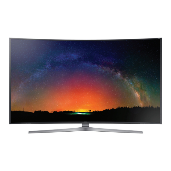
2. Product specifications 2. Product Specifications 2-1. Product information Model UN78JS9100F Front View * W : Width H : High D : Depth Detail View Color Front Color : DARK SILVER / Stand Color : DARK SILVER Without Stand 69.2 x 39.8 x 5.3 inches (1759.7 x 1012.9 x 136.0 mm) Dimensions 78"... -
Page 11: Product Specification
2-2. Product specification 2-2-1. Feature & Specifications Feature „ • Digital-TV, RF, 4-HDMI, 1-Component, 1-A/V(1Common Use for Component), 3-USB, LAN, EX-Link Specifications „ Model UN78JS9100F Item Description Screen Size (Diagonal) 78 inches Screen Curvature 4200R LCD Panel UHD 120Hz Scanning Frequency... -
Page 12: Detailed Specifications
Virtual Surround DNSe+ DTS Codec DTS Premium Sound 5.1 3D Sound Sound Customizer Sound Output (RMS) Speaker Type 4.2CH (Front Firing) Woofer Yes (Dual Woofer) HD Audio Wallmount Sound Mode Multiroom Link Smart TV Samsung SMART TV Apps Game Multi-Link Screen... - Page 13 Voice Control Face recognition Ready Motion control Ready Convergence TV to Mobile - Mirroring Mobile to TV - Mirroring, DLNA Samsung SMART View Wireless TV On - WOL Notification - BLE Briefing On TV WiDi WiFi Direct Tuner/Broadcasting Digital Broadcasting...
- Page 14 Bezel Type Slim Type Ultra-Thin Slim Front Color Dark Silver Light Effect (Deco) Stand Type Y-Shape Swivel (Left/Right) Additional Feature Samsung 3D 3D Converter Instant On Camera Built-in Wireless Copy Processor Octa-Core PX Ready 21:9 Immersive Picture Mode SCSA Support...
- Page 15 2. Product specifications Item UN78JS9100FXZA Additional Feature OSD Language English, Spanish, French Picture-In-Picture BT HID Built-in USB HID Support Feature Upgrade (Evolution Kit Ready) ATSC 3.0 Ready Teletext (TTXT) Time Shift Analog Clean View Ultra Clean View Eco Feature Energy Star Eco Sensor...
-
Page 16: Accessories
The part code for some accessories may differ depending on your region. • The provided accessories may vary depending on the model. Product Code. No Product Code. No • Samsung Smart Control BN59-01220A • User Manual BN68-06963E • Batteries (AA x 2) 4301-000101 •... -
Page 17: Viewing The Functions
EXTRA : Displays related information about the current program. EXTRA: Displays related information about the current program. When you are in a dark place, the Samsung Smart Control lights up its buttons so that you can identify : 스마트 허브를 실행합니다. 앱이 실행 중일 때, 버튼을... - Page 18 - System - Smart Control Settings - Motion Sensitivity. • To use the POINTER button and the movement of the Samsung Smart Control to operate your TV, Voice Guide must be set to Off. • To view a tutorial that shows how to use the...
- Page 19 2. Product specifications Button Description INFO Displays information about the current program or content. Guide Displays the Guide screen. Channel List Launches the Channel List. Splits the TV screen and allows you to use multiple functions - such as watching TV, Multi-Link Screen surfing the web, and playing a video - at the same time.
-
Page 20: Learning Motion Control Basics
" " 2. Product specifications 2-4-2. Learning motion control basics The following actions are available. Image Description Moving the pointer Move your hand to move the pointer accordingly. Selecting an item Fold down and raise your index finger to select items. You can select a TV menu or run a function. -
Page 21: Viewing The Panel
2. Product specifications 2-4-3. Viewing the Panel Smart Hub „ NOTE • The image may differ with the specific model and area. You can surf the web and download apps with Smart Hub. In addition, you can enjoy photo, video, and music files stored on external storage devices. - Page 22 The genre categories at the top of the screen may differ with the model and geographical area. You can download, play, and manage games or games purchased with your Samsung account. Select a game displayed on the screen or select a genre category such as Spotlight, Most Popular, What's New, or Top Grossing from the top of the screen, and then select a game in the genre you selected.
- Page 23 2. Product specifications APPS „ NOTE • To use this feature, the TV must be connected to the Internet. • When Smart Hub is launched for the first time, the default apps are automatically installed. The default apps may differ by region. You can enjoy a wide range of content including news, sports, weather and games by installing the corresponding apps on your TV.
- Page 24 You cannot play media content if the content or the storage device is not supported by the TV. For more information, refer to "Read Before Playing Photo, Video, or Music Files." • Backup important files before connecting a USB device. Samsung is not responsible for damaged or lost files. 2-15...
- Page 25 2. Product specifications NewsON „ NOTE • This function is not available in the U.S.A. and Canada. • Before you use the NewsON service, check if the TV is connected to the Internet. You can find daily information on a wide variety of topics in a smart and convenient way, updated in real time. NewsON brings you the latest headlines, top stories, popular issues, and weather forecasts.
-
Page 26: Displaying Multiple Screens
If you connect a Bluetooth headphone, you can only select Bluetooth Headphones. NOTE On the Samsung Smart Control, press the MENU/123 button, and then select Speaker List to set the speaker of each screen. 2-17... -
Page 27: Enabling The Tv To Boot Faster
NOTE • When Samsung Instant On is set to On, the use history of the apps that you used on the TV may be stored in the • The Samsung Instant On function works when you turn on the TV while its power cable is still connected after you set Samsung Instant On to On. -
Page 28: Hdmi Uhd Color
2. Product specifications 2-4-6. HDMI UHD Color Allows you to set the HDMI UHD Color mode to On or Off for each HDMI connector on the TV. When set to On, the TV optimizes processing of UHD 50P/60P signals. NOTE •... -
Page 29: Supported Formats
2. Product specifications 2-4-7. Supported Formats Supported external subtitles „ Name Format MPEG-4 Timed text .ttxt SAMI .smi SubRip .srt SubViewer .sub Micro DVD .sub or .txt SubStation Alpha .ssa Advanced SubStation Alpha .ass Powerdivx .psb SMPTE-TT Text .xml Supported internal subtitles „... - Page 30 2. Product specifications Supported music formats and codecs „ File extension Format Codec Note MPEG1 Audio *.mp3 MPEG Layer 3 *.m4a *.mpa MPEG4 *.aac *.flac FLAC FLAC Supports up to 2 channels *.ogg Vorbis Supports up to 2 channels Supports up to 10 Pro 5.1 channels. *.wma WMA lossless audio is not supported.
- Page 31 2. Product specifications Other Restrictions „ • Codecs may not function properly if there is a problem with the content. • Video content does not play or does not play correctly if there is an error in the content or container. •...
-
Page 32: Disassembly And Reassembly
3. Disassembly and Reassemble 3. Disassembly and Reassembly This section of the service manual describes the disassembly and reassembly procedures for the LED TV. This LED TV contains electrostatically sensitive devices. Use caution when handling these components. WARNING 3-1. Disassembly and Reassembly Disconnect the LED TV from the power source before disassembly. - Page 33 3. Disassembly and Reassemble Description Picture Description Screws Remove the screws from the ASSY Torque : COVER REAR. 7~8Kgf.cm • 78" : 25EA 6002-001619 M3,L5,ZPC(WHT) • ASSY COVER REAR removed form Remove the Wires and cable from connectors. Remove the ASSY SPEAKER P (L/R). Remove the screws from Stand Link and Torque :...
- Page 34 3. Disassembly and Reassemble Description Picture Description Screws...
- Page 35 3. Disassembly and Reassemble Description Picture Description Screws Remove the NETWORK. NETWORK After removing the screws of the Torque : LED DRIVER marked section, LED DRIVER (DC 7~8Kgf.cm VSS-LED TV PD BD), MAIN (ASSY PCB MAIN), SMPS (DC VSS-LED TV PD BD), FRC(ASSY PCB MAIN SUBCON).
- Page 36 3. Disassembly and Reassemble Description Picture Description Screws • 78" : Top 2EA / Bottom 2EA Torque : 4~5Kgf.cm 6003-001206 M3,L4,BLK Completed the disassembly. NOTE Reassembly procedures are in the reverse order of disassembly procedures.
-
Page 37: Troubleshooting
4. Troubleshooting 4. Troubleshooting 4-1. Previous Check Check list for initial operation „ NETWORK DC VSS-LED PD BD (LED DRIVER) ASSY PCB MAIN ASSY PCB MAIN SUBCON ASSY T CON P ASSY SPEAKER P (R/L) ASSY BOARD P-JOG FUNCTION • AC Power Cord connected to the TV and the wall receptacle. -
Page 38: How To Check Fault Symptom
4. Troubleshooting 4-2. How to Check Fault Symptom 4-2-1. Video Customer Picture Test „ One connect PCB Pre FRC Post FRC Problem Pass Pass Pass Check Signal Source and other inputs Fail Pass Pass One Connect Board or One Connect Cable Fail Fail Pass... - Page 39 4. Troubleshooting Major check points Video Test Power TV ON. Verify initial Start Up Screens with Power On. Press Mute 147 Mute to view Test Pattern from the One Connect Box. Press Mute 369 Mute to view Test Pattern from T-CON. Start Up Screens Mute 147 Mute Mute 369 Mute...
-
Page 40: Bluetooth / Wifi Module
4. Troubleshooting 4-2-2. Bluetooth / WIFI Module Bluetooth Module „ Major check points Check Bluetooth Address at Contact Samsung. BT Address Check BT Version at Factory Mode screen. Might require upgrade. Check GSPN. T-HKPAKUC-XXXX.XX T-HKPAKUS-XXXX T-HKPAKUJ-XXXX tztv-X.X 1-XXXX-X_2015XXXX.X (XXXX) BT Version BT Version : BLUETOOTH-VER-XXXX E-Manual : X.XXX... - Page 41 4. Troubleshooting WIFI Module „ Major check points Check Wired MAC Address and Wireless MAC Address at Contact Samsung. Wired MAC Address Wireless MAC Address Check Wired MAC and Wireless MAC at Factory Mode screen. (Success/Failure) Main Board is defective.
- Page 42 4. Troubleshooting 15Y BT / WIFI Combo „ • Waveforms of combo Module Pins (3.3V except VCC 5V) Stand by On state BT nReset BT Power_det BT wake up High BT USB DP & DM Don't care 60HZ signal swing (3D mode only) 3D sync in &...
-
Page 43: One Connect Box (Jack-Pack)
4. Troubleshooting 4-2-3. One Connect Box (Jack-Pack) TV Power’s On with no on screen video or menu „ Major check points Turn the TV OFF. Unplug the One-Connect cable from the TV. Turn the TV back ON, and verify the "Disconnect Banner" appears in the middle of the screen. If the "Disconnect Banner"... -
Page 44: Picture
4. Troubleshooting 4-2-4. 3D Picture Major check points Select the 3D Picture Test from the Self Diagnosis menu. Press and hold the power button on the glasses to pair them to the TV. If the operation is successful, the test image will appear in 3D and the glasses will automatically turn on. <Glasses Successfully Paired>... - Page 45 4. Troubleshooting Major check points Check the 3D picture for correct operation. If noisy it may be a defective Main PCB or T-CON Board. Replace the Main PCB or T-CON Board.
-
Page 46: Testing Smart Hub Connections
If Smart Hub is not working, select Smart Hub Connection Test. The Connection Test diagnoses the problem by checking the Internet connection, your ISP, the Samsung server, and the Apps panels. Major check points Select the Smart Hub Connection Test... -
Page 47: Jog Function Control
4. Troubleshooting 4-2-6. Jog Function Control Jog Function Control Operation „ Press Left Right Down Major check points Check Jog Shuttle STBY Voltages (All at 3.3VDC except LED). Check Jog Shuttle 5 SW Operation (Key 1 & Key 2) for each command change. Action Signal DC Voltage... -
Page 48: T-Con Board
4. Troubleshooting 4-2-7. T-CON Board Major check points Check TV Board Connector Voltages from SMPS (switched voltages on CNM803). Test for 12VDC at both sides of both fuses on the TCON Board. If either one of the fuses is open, replace the T-CON Board . If 12VDC are missing on fuses, check output feed from SMPS (CN12V, pins 1-7). -
Page 49: Factory Mode Adjustments
4. Troubleshooting 4-3. Factory Mode Adjustments 4-3-1. Detail Factory Option NOTE If you replace the main board with new one, please change the factory option as well. The options you must change are "Type". UN78JS9100FXZA „ Inches 78" Vendor PANEL Code BN95-02159A Spec. -
Page 50: Entering Factory Mode
4. Troubleshooting 4-3-2. Entering Factory Mode To enter [Service Mode] Press the remote-control keys in this sequence : • If you do not have Factory remote control Power OFF MUTE Power On • If you have Factory remote control INFO Factory •... -
Page 51: Factory Data
4. Troubleshooting 4-3-3. Factory Data Option „ Factory Menu Name Data Range Factory Reset Type 78A1UU9XJ Local Set SW Model UJS9100 BOM Model 9100 TUNER S_TDA18275A Ch Table NONE MRT Option Engineer Option Control „ Factory Menu Name Data Range EDID EDID ON/OFF EDID WRITE ALL... - Page 52 4. Troubleshooting Factory Menu Name Data Range OPTION_SWU RF Remocon Support CDD mode … DPMS Support T-CON Device Status OK LMN 1ST threshold LMN 2ND threshold LMN 3RD threshold EOS Click BP PMS Reset FAnet Thread User InstantOn Default Value CI CPLD Version ACM_MC Hotkeylist...
- Page 53 4. Troubleshooting Factory Menu Name Data Range AF Level adjust TX Power Level Mono Last Memory H Shaking SOUND High Devi *If the broadcast signal is not good, TV will complement the characteristics of the signal (most use when weak signal comes from the growing area countries) Carrier_Mute *If the noise comes from weakness-...
- Page 54 4. Troubleshooting Factory Menu Name Data Range Speaker Delay Normal NTV CU Delay Lipsync Inx Lipsync Checksum 0x5FB0 Lipsync USB Test Ready Lipsync BT Checksum 0x0028 TP volume 0xc4h TP Scale 0x6ch TP EQ CheckSum NONE Debug „ Factory Menu Name Data Range Spread Spectrum...
- Page 55 4. Troubleshooting Factory Menu Name Data Range Info Upgrade T-CON Usb Download * UpgradeT-CON eeprom T-CON CheckSum * virsion of T-CON eeprom T-CON2 Usb Download T-CON2 CheckSum PANEL EEPROM UPGRADE PANEL FLASH UPGRADE Logi Usb D/L SUBMICOM UPGRADE * Upgrade Sub-Micom Program SUBMICOM JP UPGRADE BT UPGRADE * Upgarde BT (There is upgrade program in...
- Page 56 4. Troubleshooting Factory Menu Name Data Range SVC Panel Tizen ADC/WB „ Factory Menu Name Data Range AV Calibaration Comp Calibration PC Calibration HDMI Calibration ADC Result 1st_Y_GH 1st_Y_GL 1st_Cb_BH 1st_Cb_BL 1st_Cr_RH 1st_Cr_RL 2nd_R_L 2nd_G_L 2nd_B_L 2nd_R_H 2nd_G_H 2nd_B_H White Balance R-Offset G-Offset B-Offset...
- Page 57 4. Troubleshooting Factory Menu Name Data Range WB_W2_N_Gain WB_W2_N_Gain MGA On/Off R1_Gain G1_Gain B1_Gain R2_Gain G2_Gain B2_Gain R3_Gain G3_Gain B3_Gain R4_Gain G4_Gain B4_Gain R5_Gain G5_Gain B5_Gain R6_Gain G6_Gain B6_Gain R7_Gain G7_Gain B7_Gain R8_Gain G8_Gain B8_Gain R9_Gain G9_Gain B9_Gain R10_Gain G10_Gain B10_Gain Advanced „...
-
Page 58: White Balance
4. Troubleshooting 4-4. White Balance 4-4-1. Calibration Into the Factory Mode. Select ADC/WB menu. Select menu. AV Calibration Option Comp Calibration Control PC Calibration Debug HDMI Calibration ADC/WB Advanced 4-4-2. Service Adjustment You must perform Calibration in the Lattice Pattern before adjusting the White Balance. Color Calibration „... - Page 59 4. Troubleshooting Method of Color Calibration (AV) „ Apply the NTSC Lattice (N0. 3) pattern signal to the AV IN 1 port. Press the Source key to switch to “AV1” mode. Enter Service mode. Select the “ADC” menu. Select the “AV Calibration” menu. In “AV Calibration Off” status, press the “► ” key to perform Calibration.
-
Page 60: Adjustment
4. Troubleshooting 4-4-3. Adjustment Into the Factory Mode. ADC/WB Select menu. Select White Balance menu. Option Control Debug (Low Light) (Hight Light) Sub Brightness Sub Contrast White Balance ADC/WB R offset R gain Advanced G offset G gain B offset B gain 4-24... -
Page 61: Rs-232C
4. Troubleshooting 4-5. RS-232C • RS232C Control Port : COM#(Serial) Bit rate : 115200 Data Bit : 8 bit Parity : None Stop Bits : 1 Flow Control : None • Description of RS232C Pin# Name Full Name Pin# Name Full Name Pin# Name Full Name... -
Page 62: Av Control Tabe
4. Troubleshooting 4-6. AV Control Tabe Control Item Cmd1 Cmd2 Cmd3 Value General Power Power 0x00 0x00 0x00 0x00 0x01 0x02 Volume Direct 0x01 0x00 0x00 (0~100) 0x01 0x00 Down 0x02 0x00 Mute 0x02 0x00 0x00 0x00 Direct 0x04 Continuous 0x01 0x00 0x03... - Page 63 4. Troubleshooting Control Item Cmd1 Cmd2 Cmd3 Value PICTURE Mode CAL-NIGHT 0x04 CAL-DAY 0x05 BD Wise 0x06 Relax New function of 12" 0x07 (only PDP TV) BackLight 0~20 0x01 0x00 (0~20) (CellLight) Contrast 0~100 0x02 0x00 (0~100) Brightness 0~100 0x03 0x00 (0~100) Sharpness...
- Page 64 4. Troubleshooting Control Item Cmd1 Cmd2 Cmd3 Value PICTURE 0x01 xvYCC 0x10 0x00 0x01 Motion Lighting 0x11 0x00 0x01 LED Motion Plus 0x0a 0x07 0x00 On(Normal) 0x01 Cinema 0x02 Ticker 0x03 Picture Color Tone Cool 0x0a 0x00 0x00 Option Change Normal → Standard 0x01 Standard mode...
- Page 65 4. Troubleshooting Control Item Cmd1 Cmd2 Cmd3 Value PICTURE Demo 0x05 Screen Picture Size 16:9 0x0b 0x0a 0x01 0x00 Adjustment Zoom1 0x01 Zoom2 0x02 Wide Fit 0x03 0x04 Screen Fit 0x05 Smart View I 0x06 Smart View II 0x07 Auto Wide 0x08 New function of 12"...
- Page 66 4. Troubleshooting Control Item Cmd1 Cmd2 Cmd3 Value Sound Equalizer Balance 0x01 0x00 (0~20) 100hz 0x01 (0~20) 300hz 0x02 (0~20) 1khz 0x03 (0~20) 3khz 0x04 (0~20) 10khz 0x05 (0~20) Reset 0x06 0x00 TruSurround 0x02 0x00 0x00 HD (echo) Virtual Surrond 0x01 (echo) TruDialog...
- Page 67 4. Troubleshooting Control Item Cmd1 Cmd2 Cmd3 Value Key Generation refer to 0x0d 0x00 0x00 table Show/Hide Show 0x0e 0x00 0x00 0x00 Control New function of 12" Hide 0x01 Power (On/Off) 0xf0 0x00 0x00 0x00 Status Volume(0~100) 0xf0 0x01 0x00 0x00 Mute (On/Off) 0xf0...
-
Page 68: Updating The Tv's Software
4. Troubleshooting 4-7. Updating the TV’s Software • MENU/123 MENU Support Software Update You can view your TV’s software version and update it if necessary. Updating the TV’s software to the latest version „ • MENU/123 MENU Support Software Update Update now You can update your TV’s software by downloading the update from the Internet directly to your TV or copying the update from a USB device that contains it to your TV. -
Page 69: Wiring Diagram
5. Wiring Diagram 5. Wiring Diagram 5-1. Wiring Diagram... -
Page 70: Connector
5. Wiring Diagram 5-2. Connector 5-2-1. Main Board CN203 CN202 CN1001_DB CN902_DB CN801 CN203 CN1103_DB CN1102_N8 CN1102 CN301 CN201 Main Board Pin Map „ CN1002_N8 CN203 (POWER) B5V_USB_MOIP_PW MOIP+_USB DGND DGND MOIP-_USB DGND DGND DGND B13V_PW B18VS_PW DGND B18VS_PW B13V_PW B18VS_PW B13V_PW DGND... - Page 71 5. Wiring Diagram CN902_DB (ARM JTAG) CN201 (SERDES) B3.3V_PW SERDES_TCK B3.3V_PW SERDES_RX2- SERDES_TRST_L SERDES_TDO GCLK1_CLK DGND SERDES_TDI MRST DGND SERDES_RX1+ SERDES_TMS DGND SERDES_TX1+ SERDES_RX1- SERDES_TX1- DGND CN203 (VBY1) DGND SERDES_RX5+ IDENT_JACKPACK UHDVIDEO_F-_VBY1 SERDES_RX4+ SERDES_RX5- FRC_SDA_I2C DGND SERDES_RX4- A5V_PW AGING_EN 29 UHDVIDEO_G+_VBY1 DGND TX_MICOM_JACK FRC_SCL_I2C...
- Page 72 5. Wiring Diagram CN801 (BT/WIFI COMBO) BT_NRESET REF_SYNC_IN POWER_DET DGND WAKE_BT DGND A5V_PW WIFI+_USB BT-_USB WIFI-_USB BT+_USB A5V_PW DGND WAKE_ON_LAN BT_SYNC_BUFF WIFI_NRESET CN202 (LD) DGND LD_SDA_I2C DGND B5V_PW LD_SCL_I2C DGND CN1101_DB (SUMICOM DEBUG) DGND DOUT DGND...
-
Page 73: Jackpack Board (One Connect)
5. Wiring Diagram 5-2-2. Jackpack Board (One connect) CN2301 CN2102 CN1801 CN403 CN1803 CN501 CN1802 CN801 CN803 CN502 CN3301 CN402 CN2003 CN802 CN804 CN602_RS CN1701 Jackpack Board (One connect) Pin Map „ CN2301_DB (IRB) CN3301 (SERDES) A5V_PW IRB_UART_TXD B3.3V_PW SERDES_T2- SUB_RESET DGND GCLK1_CLK... - Page 74 5. Wiring Diagram CN502 (COMPONENT) CN802 (HDMI INPUT 2 DVI_PC) DGND COMP_PR HDMI2_RX2+_HDMI DGND AV1_CVBS_IN DGND DGND 12 HDMI2_RXCLK-_HDMI DGND COMP_PB HDMI2_RX2-_HDMI HDMI_CEC COMP_AV1_SL_IN IDENT_COMP_Y HDMI2_RX1+_HDMI ARC_SINGLE DGND HP_AUD_SL_OUT DGND HDMI2_SCL_DDC COMP_AV1_SR_IN DGND HDMI2_RX1-_HDMI HDMI2_SDA_DDC DGND HP_AUD_SR_OUT HDMI2_RX0+_HDMI DGND COMP_Y IDENT_CVBS DGND HDMI2_5V_PW...
- Page 75 5. Wiring Diagram CN403 (OPTICAL) HAWK_SPDIF_OUT DGND B5V_USB_OP_WIFI_CI_PW CN501 (FAN) FAN_ERROR VOUT DGND...
-
Page 76: Smps Board
5. Wiring Diagram 5-2-3. SMPS Board CN803 CNM803 CNT804 SMPS Board Pin Map „ CN803 CN803 B13V FAIL B13V B13V B13V B13V VDRV VDRV B13V VDRV 11 12 VDRV B13V 11 12 VDRV 13 14 VDRV B13V 13 14 VDRV 15 16 VDRV VDRV... -
Page 77: Ldc Board
5. Wiring Diagram 5-2-4. LDC Board CNL802B CNL803A CNL802A CNL803B CN800B CN9003 LDC Board Pin Map „ CNL802B CNL803A T21 (+) T11 (+) T44 (-) 17 18 T34 (-) T21 (-) T11 (-) T44 (+) 15 16 T34 (+) T22 (+) T12 (+) T43 (-) 13 14... - Page 78 5. Wiring Diagram CNL802B CNL803A CNL802A CNL803B CN800B CN9003 LDC Board Pin Map „ CN9003 CN800B PWM_08 25 26 B13V 21 22 FAIL PWM_09 23 24 19 20 PWM_10 21 22 PWM_01 17 18 PWM_11 19 20 PWM_02 15 16 17 18 VDRV 13 14...
-
Page 79: T-Con Board
5. Wiring Diagram 5-2-5. T-CON Board CON5 CON_12V CON_SFL CON_SFR CON_SBL CON_SBR T-CON Board Pin Map „ CON5 U2 (TCON VBY1 INPUT RX FROM FRC) 12V_PW_EN RX15_P 12V_PW_EN RX8_N 12V_PW_EN RX8_P 3D_SYNC_O AGING_ENI RX9_N 3D_SYNC_I PWM_DIMMING_ B_INT RX9_P OUT13 SDA_I PWM_DIMMING_ SCL_I OUT14... - Page 80 5. Wiring Diagram U1 (TCON VBY1 INPUT RX FROM FRC) CON_SFL(OUTPUT BLOCK) VIN_12V AVDD_TAO_15V VIN_12V RX3_N AVDD_TAO_15V US2E_P VIN_12V RX3_P US2E_N VIN_12V VIN_12V RX4_N HAVDD_TAO_7.5V US2O_P VIN_12V RX4_P HAVDD_TAO_7.5V US2O_N VIN_12V VIN_12V RX5_N US3E_P VIN_12V RX5_P VCC_1.8V US3E_N VIN_12V VCC_1.8V RX6_N US3O_P RX6_P...
- Page 81 5. Wiring Diagram CON_SFR (OUTPUT BLOCK) CON_SBL (OUTPUT BLOCK) FB33_1 US15E_P US11E_P FB33_4 US15E_N US11E_N VCC_3.3V AVDD_TBO_15V US15O_P U11O_P AVDD_TBO_15V US15O_N SCL_AMC1 US11O_N SDA_AMC1 US16E_P US12E_P HAVDD_TBO_7.5V US16E_N SCL_AMC2 US12E_N HAVDD_TBO_7.5V SDA_AMC2 US16O_P US12O_P US16O_N US7E_P US12O_N US7E_N VCC_TB_1.8V US17E_P SFC1 VCC_TB_1.8V US17E_N...
- Page 82 5. Wiring Diagram CON_SBR (OUTPUT BLOCK) FB33_3 US24E_P US24E_N SFC2 US24O_P US19E_P US24O_N US19E_N US19O_P VCS1 US19O_N VCS1 US20E_P VCST1 US20E_N BVOFF1_-11V US20O_P US20O_N VCC_3.3V STV1 US21E_P CPV1 US21E_N CPV3 US21O_P BVON_O_28V US21O_N BVON_O_28V US22E_P BVOFF2_-7.6V US22E_N VCC_1.8V US22O_P VCC_1.8V US22O_N US23E_P HAVDD_TAO_7.5V...
-
Page 83: Frc Board
5. Wiring Diagram 5-2-6. FRC Board CN803 CN802 CN800 CN801 CN400_MAIN CN801 CN800 FRC Board Pin Map „ CN803 (TO LD BOARD) CN802 (MICOM JTAG) DGND 11 PWM_DIMMING_OUT8 B3.3V_PW M_TDO DGND 12 PWM_DIMMING_OUT9 M_NTRST FP_NRESET PWM_DIMMING_ M_TDI DGND 3 PWM_DIMMING_OUT1 13 OUT10 M_TMS FRC_SDA_I2C... - Page 84 5. Wiring Diagram CN400_MAIN(FROM MAIN) IN_B12V_PW DGND RX_5+_VBY1 IN_B12V_PW RX_0-_VBY1 DGND IN_B12V_PW RX_0+_VBY1 RX_6-_VBY1 IN_B12V_PW DGND RX_6+_VBY1 IN_B12V_PW RX_1-_VBY1 DGND IN_B12V_PW RX_1+_VBY1 RX_7-_VBY1 IN_B12V_PW DGND RX_7+_VBY1 IN_B12V_PW RX_2-_VBY1 DGND IN_B12V_PW RX_2+_VBY1 MAIN_CHECK IN_B12V_PW DGND TCON_SCL_I2C RX_3-_VBY1 TCON_EN_I2C DGND RX_3+_VBY1 TCON_SDA_I2C DGND DGND BT_SYNC...
- Page 85 5. Wiring Diagram CN800_TCON (TO TCON) PANEL_DETECT0 TX_5-_VBY1 VB1_LOCKN_TX PANEL_DETECT1 DGND VB1_HTPDN_TX AGING_EN TX_4+_VBY1 DGND PANEL_PMIC_EN TX_4-_VBY1 DGND EEPROM_WP DGND DGND TCON_SDA_I2C TX_3+_VBY1 DGND TCON_EN_I2C TX_3-_VBY1 TCON_SCL_I2C DGND PANEL_12V_PW 3D_ENABLE TX_2+_VBY1 PANEL_12V_PW DGND TX_2-_VBY1 PANEL_12V_PW TX_7+_VBY1 DGND PANEL_12V_PW TX_7-_VBY1 TX_1+_VBY1 PANEL_12V_PW DGND TX_1-_VBY1...
-
Page 86: Annex. Exploded View & Part List [Un78Js9100Fxza Ts01]
ANNEX. Exploded View & Part List ANNEX. Exploded View & Part List [UN78JS9100FXZA TS01] 1-1. Exploded View 1-1-1. Parts List Code No. Description & Specification Q’ty SA/SNA Remark BN95-02159A PRODUCT LCD-SDC; CY-XJ078FLLV1V/H,JS9000, BN96-37056A ASSY CHASSIS TOP P; JQ9K 78",STS BN96-36899A ASSY SPEAKER P;... -
Page 87: Parts List
ANNEX. Exploded View & Part List 1-2. ONE CONNECT Exploded View 1-2-1. Parts List Code No. Description & Specification Q’ty SA/SNA Remark BN63-13593B COVER-TOP; JS9000 ONE-CONNECT,ABS+PC,Amer BN94-09102U ASSY PCB MISC-JACKPACK; JS9.1K,78",NORTH BN62-00729A HEAT SINK-FAN MODULE; Jackpack,A1050,BLAC BN96-35586B ASSY COVER P-BOTTOM; JQ9000 65",ABS+PC 6003-001086 SCREW-TAPTYPE;... -
Page 88: Electrical Parts List
ANNEX. Exploded View & Part List 2-1. Electrical Parts List Service Bom (SA: SERVICE AVAILABLE, SNA: SERVICE NOT AVAILABLE) Level Location No. Code No. Description & Specification Q’ty SA/SNA Remark UN78JS9100FXZA (TS01) R001A BN90-07483A ASSY COVER REAR;JS9K 78" 6002-001619 SCREW-TAPPING;BH,+,S type,M3,L5,ZPC(WHT) R001A BN96-37728A ASSY COVER P-REAR;JS9.1K,NORTH AMERICA,P... - Page 89 ANNEX. Exploded View & Part List Level Location No. Code No. Description & Specification Q’ty SA/SNA Remark ...4 BN61-11636A LGP-LED;78inch JS9K, Lenticular,MS,1738..4 BN63-13564A SHEET-MLS;UTE23C-10B,PET,0.295,1731.22,9 ...4 BN63-13565A SHEET-REFLECTOR;SRE885C,PET,0.285,1740.6 ...4 BN63-13988A SHEET-PRISM;UTE34G-13LP,PET,0.425,1731.2 ...4 BN63-13989A SHEET-DBEF;DBEF D2 400,PC,0.4,1731.22,97 ...4 BN63-13990A SHEET-QD;UTQ10-9B,PET,0.34,1738.04,975.6 ...4 BN96-37048A ASSY CHASSIS BOTTOM P;JQ9000 78,BN64-031 ..5...
- Page 90 ANNEX. Exploded View & Part List Level Location No. Code No. Description & Specification Q’ty SA/SNA Remark ..5 BN60-01245D SPACER-PANEL D B;JS9000 78",SI,310,GRAY, ..5 BN61-12232A FRAME-MOLD,MIDDLE D;JQ9000 78",PBT+GF,PC ...4 BN96-37051A ASSY FRAME P-MOLD MIDDLE LR;JQ9000 78",P ..5 BN60-00919T SPACER-LGP LR;JS9000 78",SI,965,WHITE,T0 ..5 BN60-01245E SPACER-PANEL LR A;JS9000 78",SI,487,GRAY...
- Page 91 ANNEX. Exploded View & Part List Level Location No. Code No. Description & Specification Q’ty SA/SNA Remark ...4 0505-001844 FET-SILICON;SI4435DDY-T1-GE3,P,-30V,-11..4 0505-002598 FET-SILICON;AP2317GN,P,-20V,-4.2A,0.052o ...4 0801-000796 IC-CMOS LOGIC;7S32,OR GATE,SOT-353,5P,51 ...4 0801-003292 IC-CMOS LOGIC;7WB66,Bus Switch,MAB08A,8P ...4 0801-003424 IC-CMOS LOGIC;74VHCV541,Octal schmitt bu ...4 1006-001576 IC-DRIVER/RECEIVER;MAX3221ECPWR,TSSOP,16 ...4...
- Page 92 ANNEX. Exploded View & Part List Level Location No. Code No. Description & Specification Q’ty SA/SNA Remark ...4 BN97-09486A ASSY MICOM-SPI;HAWK_N SPI,JS9000,W25Q128 ..5 1107-002210 IC-NOR FLASH;W25Q128FVSIG,128Mbit,128Mx1 BN94-08623A ASSY PCB MAIN SUBCON;JS9K,78",HAWK UFP AH020 BN62-00718A HEAT SINK;Hawk_UFP Heat Sink,A1050,1.5mm BN97-09357B ASSY SMD;JQ9K,BN41 ...4 0403-001164 DIODE-ZENER;MMSZ5232B,5.32-5.88V,500MW,S...
- Page 93 ANNEX. Exploded View & Part List Level Location No. Code No. Description & Specification Q’ty SA/SNA Remark BN64-03023A BADGE-BRAND;JU7500,Ni,0.09,4.5,30,SILVER T0527 BN68-00513A LABEL-E,PASS;ALL MODEL,YUPO(110G),BLACK, BN68-07281A LEAFLET;2015 One Connect,ENG,WW,ART*,105 BN69-11508A BOX UNIT-SET;ONE CONNECT,CB,NONSTANDARD, BN94-09102U ASSY PCB MISC-JACKPACK;JS9.1K,78",NORTH BN62-00574A HEAT SINK-ES;F7000,A6063,ANODIZING,28*14 BN62-00729A HEAT SINK-FAN MODULE;Jackpack,A1050,BLAC T0527 BN68-00513A LABEL-E,PASS;ALL MODEL,YUPO(110G),BLACK,...
- Page 94 ANNEX. Exploded View & Part List Level Location No. Code No. Description & Specification Q’ty SA/SNA Remark ...4 1203-008112 IC-POSI.ADJUST REG.;AOZ2002PI,SO-8,8P,4..4 1203-008118 IC-DC/DC CONVERTER;AOZ3013PI,SO-8,8P,4.9 ...4 1203-008139 IC-DC/DC CONVERTER;TPS56C20PWPR,HTSSOP,2 ...4 1203-008454 IC-DC/DC CONVERTER;TPS56528,HSOP8,8P,4,8 ...4 1203-008471 IC-POSI.ADJUST REG.;SOT-23-5,5P,3.020X2..4 1204-003579 IC-VIDEO PROCESS;SDP1407,FCLBGA,510P,21x ...4 1204-003582 IC-VIDEO PROCESS;SDP-1408,FCPBGAH,849P,2...
- Page 95 ANNEX. Exploded View & Part List Level Location No. Code No. Description & Specification Q’ty SA/SNA Remark ...4 2007-007314 R-CHIP;5.6Kohm,1%,1/16W,TP,1005 ...4 2007-007315 R-CHIP;3.9Kohm,1%,1/16W,TP,1005 ...4 2007-007317 R-CHIP;2.2Kohm,1%,1/16W,TP,1005 ...4 2007-007318 R-CHIP;1Kohm,1%,1/16W,TP,1005 ...4 2007-007334 R-CHIP;200Kohm,1%,1/16W,TP,1005 ...4 2007-007468 R-CHIP;121Kohm,1%,1/16W,TP,1005 ...4 2007-007470 R-CHIP;7.5Kohm,1%,1/16W,TP,1005 ...4 2007-007488 R-CHIP;75Kohm,1%,1/16W,TP,1005 ...4 2007-007517...
- Page 96 ANNEX. Exploded View & Part List Level Location No. Code No. Description & Specification Q’ty SA/SNA Remark ...4 AD480 2203-000278 C-CER,CHIP;0.01nF,0.5pF,50V,C0G,TP,1005 ...4 AD480 2203-000330 C-CER,CHIP;0.012nF,5%,50V,C0G,TP,1005 ...4 AD480 2203-000359 C-CER,CHIP;0.15nF,5%,50V,C0G,TP,1005,0.5 ...4 AD480 2203-000425 C-CER,CHIP;0.018nF,5%,50V,C0G,TP,1005 ...4 AD480 2203-000438 C-CER,CHIP;1nF,10%,50V,X7R,TP,1005 ...4 AD480 2203-000489 C-CER,CHIP;2.2nF,10%,50V,X7R,TP,1005 ...4 AD480...
- Page 97 ANNEX. Exploded View & Part List Level Location No. Code No. Description & Specification Q’ty SA/SNA Remark ...4 2703-000158 INDUCTOR-SMD;1uH,10%,2012,.4Ohm,50mA,45, ...4 2703-000213 INDUCTOR-SMD;470nH,10%,1608,1.35Ohm,35mA ...4 2703-001938 INDUCTOR-SMD;56nH,5%,1005,1.5Ohm,200mA,1 ...4 2703-003713 INDUCTOR-SMD;1.5uH,20%,7366,0.015ohm,700 ...4 2703-003937 INDUCTOR-SMD;1uH,20%,7.0x6.47x3.0mm,0.00 ...4 2703-005191 INDUCTOR-SMD;1.5uH,20%,6060,4.5,0.02ohm, ...4 2703-005192 INDUCTOR-SMD;4.7uH,20%,6060,4.5,0.036ohm ...4 2703-005193 INDUCTOR-SMD;2.2uH,20%,6060,4.5,0.024ohm ...4 2703-005194...
- Page 98 ANNEX. Exploded View & Part List Level Location No. Code No. Description & Specification Q’ty SA/SNA Remark BN67-00327M RUBBER-FOOT;STAND,SILICON,10*10,T1.5,GRA BN91-15412A ASSY SHIELD;JS9K 78" SCREW 6001-002789 SCREW-MACHINE;BH,+,M4,L6,ZPC(WHT),SWRCH1 SCREW 6001-003016 SCREW-MACHINE;PWH,+,M3.0,L5.0,ZPC(WHT),S SCREW 6003-001206 SCREW-TAPTYPE;BH,+,B,M3,L4,BLK,SWRCH18A BN02-00102B TAPE-FILAMENT;#8917,0.15,25,50,WHITE EC13 BN39-02007G LEAD CONNECTOR;78JS9000,Flat Connector*, EC13 BN39-02009D LEAD CONNECTOR;78JS9000,Flat Connector*, BN39-02011B...
- Page 99 T0268 3903-000466 CBF-POWER CORD;DT,US,EP3,IEC320 C13,125/ 4301-000101 BATTERY-ALKALINE;1.5V,1650mAH,LR6,14.5x5 EC03 BN39-01900A CBF SIGNAL;UN55HU9000FXZA,18P*,CBF CABLE REMOCON BN59-01220A REMOCON-15SMART CONTROL;TM1560,18,70mA,3 BN68-04972E LEAFLET-04,REGULATORY GUIDE;ALL,SAMSUNG, BN68-05723A LABEL-ACCESSORY;ALL MODELS,YUPO,0.2,20,7 BN68-06963E MANUAL USERS;JS9100,United States,W/P* BN68-07429B LEAFLET-RMH GUIDE;Common,ZA,W/P* BN69-08751A WRAP VINYL-SHRINK;STAND,PLASTIC OTHERS,P BN69-10158A BOX ACCESSORY;H8000_ACCESSORY,CB,SERP Re BN69-10161A PAD-TYPE;H8000_ACCESSORY,CB,SERP Recycle BN69-11826A PAD ACCESSARY;JQ8500 ACCESSORY-BOX-REMOC...