Fujitsu AIRSTAGE ARXA030GLEH Installation Manual
Hide thumbs
Also See for AIRSTAGE ARXA030GLEH:
- Operating manual (6 pages) ,
- Design & technical manual (1092 pages)
Table of Contents
Advertisement
Quick Links
ARXA024GLEH
ARXA030GLEH
ARXA036GLEH
ARXA045GLEH
Refer to the rating label for the serial number,
manufactured year and month.
TM
INSTALLATION MANUAL
INSTALLATIONSANLEITUNG
MANUEL D'INSTALLATION
MANUAL DE INSTALACIÓN
Únicamente para personal de servicio autorizado.
MANUALE DI INSTALLAZIONE
A uso esclusivo del personale tecnico autorizzato.
ΕΓΧΕΙΡΙΔΙΟ ΕΓΚΑΤΑΣΤΑΣΗΣ
ΕΣΩΤΕΡΙΚΗ ΜΟΝΑΔΑ (Τύπος αγωγού)
Μόνο για εξουσιοδοτημένο τεχνικό προσωπικό.
MANUAL DE INSTALAÇÃO
UNIDADE INTERIOR (Tipo de tubagem)
РУКОВОДСТВО ПО УСТАНОВКЕ
Только для авторизованного обслуживающего персонала.
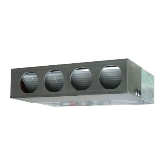
INDOOR UNIT (Duct type)
For authorized service personnel only.
INNENGERÄT (Kanaltyp)
Nur für autorisiertes Fachpersonal.
UNITÉ INTÉRIEURE (type conduit)
Pour le personnel agréé uniquement.
UNIDAD INTERIOR (Tipo conducto)
UNITÀ INTERNA (tipo a condotto)
Apenas para técnicos autorizados.
ВНУТРЕННИЙ МОДУЛЬ (Короб)
MONTAJ KILAVUZU
İÇ ÜNİTE (Kanal tipi)
Yalnızca yetkili servis personeli için.
[Original instructions]
PART No. 9373385257
MADE IN P.R.C.
Advertisement
Table of Contents

Related Manuals for Fujitsu AIRSTAGE ARXA030GLEH


Summary of Contents for Fujitsu AIRSTAGE ARXA030GLEH
- Page 1 INSTALLATION MANUAL INDOOR UNIT (Duct type) For authorized service personnel only. INSTALLATIONSANLEITUNG INNENGERÄT (Kanaltyp) Nur für autorisiertes Fachpersonal. MANUEL D’INSTALLATION UNITÉ INTÉRIEURE (type conduit) Pour le personnel agréé uniquement. MANUAL DE INSTALACIÓN UNIDAD INTERIOR (Tipo conducto) ARXA024GLEH Únicamente para personal de servicio autorizado. ARXA030GLEH MANUALE DI INSTALLAZIONE ARXA036GLEH...
-
Page 2: Table Of Contents
INSTALLATION MANUAL This mark indicates procedures which, if improperly performed, CAUTION might possibly result in personal harm to the user, or damage to PART No. 9373385257 property. VRF system indoor unit (Duct type) Read carefully all security information before use or install the air conditioner. Contents Do not attempt to install the air conditioner or a part of the air conditioner by yourself. -
Page 3: Accessories
2.3. Accessories 2.4. Optional parts When connecting the square duct and round duct, use the optional square flange or WARNING round fl ange. For installation purposes, be sure to use the parts supplied by the manufacturer or Square fl ange other prescribed parts. -
Page 4: Installation Work
[Top view] 3. INSTALLATION WORK (unit : mm) 500 or more Correct initial installation location is important because it is difficult to move unit after it is installed. 3.1. Selecting an installation location Indoor unit WARNING Service access Select installation locations that can properly support the weight of the indoor. Install the units securely so that they do not topple or fall. - Page 5 3.3.4. Outlet duct WARNING Duct installation pattern ( CUT PART) When fastening the hangers, make the bolt positions uniform. Round duct outlet 4 (Factory setting.) The distance of ※ is adjustable according to the place of the hanging bolts. (MAX : 550 mm, MIN : 410 mm) Slide the unit in the arrow direction and fasten it.
-
Page 6: Pipe Installation
CAUTION 4. PIPE INSTALLATION To prevent people from touching the parts inside the unit, be sure to install grilles on the inlet and outlet ports. The grilles must be designed in such a way that cannot be CAUTION removed without tools. Be more careful that foreign matter (oil, water, etc.) does not enter the piping than with If an intake duct is installed, take care not to damage the temperature sensor (the refrigerant R410A models. -
Page 7: Installing Heat Insulation
4.3.1. Flaring Tighten with 2 wrenches. • Use special fl are tool exclusive for R410A. Holding wrench (1) Cut the connection pipe to the necessary length with a pipe cutter. (2) Hold the pipe downward so that cuttings will not enter the pipe and remove any Flare nut burrs. - Page 8 (Right side) Applying 240 mm area of adhesive Joint pipe Hard PVC side (locally purchased) Drain pipe (VP25) (locally purchased) 4 mm or less Wrap the Drain hose insulation around the drain hose connection. Liquid pipe Drain hose insulation Gas pipe (Accessories) Drain port Drain pan...
-
Page 9: Electrical Wiring
6. ELECTRICAL WIRING 6.1. Electrical requirement WARNING Voltage rating 230 V Operating range 198 to 264 V (50 Hz) Electrical work must be performed in accordance with this Manual by a person certifi ed under the national or regional regulations. Be sure to use a dedicated circuit for the 198 to 253 V (60 Hz) unit. -
Page 10: Wiring Method
WARNING 6.2. Wiring method When using solid core cables, do not use the ring terminal. If you use the solid core Example cables with the ring terminal, the ring terminal's pressure bonding may malfunction and cause the cables to abnormally heat up. Outdoor unit or RB unit *1 B. -
Page 11: Connection Of Wiring
6.4. Connection of wiring 6.5. Optional parts wiring 6.5.1. Layout of the indoor unit PCB (1) Remove the control box cover and install each connection cable. Power supply PCB Controller PCB CNB01 CNA01 CNA03 CNA02 CNA04 CN48 CNA05 Power indicator lamp (green) Control box cover Screw... -
Page 12: External Input And External Output (Optional Parts)
Wiring arrangement When connected to Apply voltage terminals of multiple indoor units with a connected unit, be sure to make a branch outside the indoor unit using a pull box, etc. as shown on below In following figure, all the possible connectors are connected for description. example. -
Page 13: Remote Sensor (Optional Parts)
● When function setting is “Operation/Stop” mode. Output select [In the case of “Edge” input] ● When indicator etc. are connected directly Connector Input signal Command P.C.B OFF → ON Operation Operation Ch1 of CNA01 or CNA02 indicator ON → OFF Stop Error indicator... -
Page 14: Field Setting
7. FIELD SETTING 7.2. Custom code setting Selecting the custom code prevents the indoor unit mix-up. There are 3 methods for address setting by FIELD SETTING as follows. (Up to 4 codes can be set.) Set by either of the methods. Perform the setting for both the indoor unit and the remote controller. -
Page 15: Function Setting
Function 7.4. Function setting Function Setting number Default Details number 00 0°C • FUNCTION SETTING can be performed with the wired or wireless remote controller. 01 0.5°C (The remote controller is optional equipment) 02 1.0°C • Refer to the wired or wireless remote controller manual for detailed setting information. •... -
Page 16: Error Codes
10. ERROR CODES If you use a wired type remote controller, error codes will appear on the remote controller display. If you use a wireless remote controller, the lamp on the photodetector unit will output error codes by way of blinking patterns. See the lamp blinking patterns and error codes in the table below.