Table of Contents
Advertisement
Quick Links
Catalyst 6500 Series DFC, DFC3A, DFC3B, and
DFC3BXL Installation Note
Product numbers:
WS-F6K-DFC(=)
WS-F6K-DFC3A(=)
WS-F6K-DFC3B(=)
WS-F6K-DFC3BXL(=)
Throughout this publication, unless otherwise noted, the term DFC refers to the DFC, DFC3A, DFC3B,
Note
and DFC3BXL.
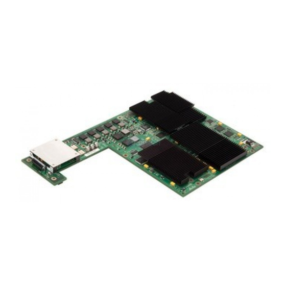
This publication describes how to install the Catalyst 6500 series Distributed Forwarding Card (DFC)
on Catalyst 6500 series fabric-enabled modules.
You can only install the DFC on fabric-enabled modules. See the
Note
Requirements" section on page 2
Contents
This publication contains these sections:
•
•
•
•
•
Corporate Headquarters:
Cisco Systems, Inc., 170 West Tasman Drive, San Jose, CA 95134-1706 USA
Copyright © 2001-2005 Cisco Systems, Inc. All rights reserved.
Safety Overview, page 3
Parts List, page 7
Required Tools, page 8
Installation Guidelines, page 8
for more information.
"Hardware and Software
Advertisement
Table of Contents

Related Manuals for Cisco Catalyst DFC3A


Summary of Contents for Cisco Catalyst DFC3A
-
Page 1: Table Of Contents
• • Required Tools, page 8 Installation Guidelines, page 8 • Corporate Headquarters: Cisco Systems, Inc., 170 West Tasman Drive, San Jose, CA 95134-1706 USA Copyright © 2001–2005 Cisco Systems, Inc. All rights reserved. “Hardware and Software for more information. -
Page 2: Hardware And Software Requirements
Hardware and Software Requirements Removing the DFC, page 9 • Installing the DFC, page 12 • Related Documentation, page 19 • Obtaining Documentation, page 19 • Hardware and Software Requirements The requirements for using the DFC or DFC3A are as follows: DFC Hardware and Software Requirements, page 2 •... -
Page 3: Safety Overview
DFC3A, DFC3B, DFC3BXL Hardware and Software Requirements To install and use the DFC3A, DFC3B, or DFC3BXL, you need the following: Catalyst 6500 series switch (Catalyst 6503, 6506, 6509, 6509-NEB, or 6513) or Cisco 7600 series • router (Cisco 7603, 7606, 7609, or 7613) •... - Page 4 Safety Overview Warning IMPORTANT SAFETY INSTRUCTIONS This warning symbol means danger. You are in a situation that could cause bodily injury. Before you work on any equipment, be aware of the hazards involved with electrical circuitry and be familiar with standard practices for preventing accidents. To see translations of the warnings that appear in this publication, refer to the translated safety warnings that accompanied this device.
- Page 5 Safety Overview Attention IMPORTANTES INFORMATIONS DE SÉCURITÉ Ce symbole d'avertissement indique un danger. Vous vous trouvez dans une situation pouvant causer des blessures ou des dommages corporels. Avant de travailler sur un équipement, soyez conscient des dangers posés par les circuits électriques et familiarisez-vous avec les procédures couramment utilisées pour éviter les accidents.
- Page 6 Safety Overview Advarsel VIKTIGE SIKKERHETSINSTRUKSJONER Dette varselssymbolet betyr fare. Du befinner deg i en situasjon som kan forårsake personskade. Før du utfører arbeid med utstyret, bør du være oppmerksom på farene som er forbundet med elektriske kretssystemer, og du bør være kjent med vanlig praksis for å unngå ulykker. For å se oversettelser av advarslene i denne publikasjonen, se de oversatte sikkerhetsvarslene som følger med denne enheten.
-
Page 7: Parts List
Warning Only trained and qualified personnel should be allowed to install, replace, or service this equipment. Parts List These parts are in the DFC kit: One Catalyst 6500 series DFC, DFC3A, DFC3B, or DFC3BXL • One disposable grounding wrist strap •... -
Page 8: Required Tools
Required Tools Required Tools These tools are required to install the Catalyst 6500 series DFC: Antistatic mat or foam pad to support the removed module • Number 1 Phillips screwdriver for the screws and cap nuts that fasten the DFC to the module •... -
Page 9: Removing The Dfc
Use care not to damage the connectors on the module. If you damage a connector, it will be Caution necessary to return the module to Cisco for repair. You must install screws in all available standoffs. The screws provide grounding between the Caution DFC3 and the module. - Page 10 Removing the DFC Figure 1 DFC Securing Screws and Cap Nuts WS-X5530 Grasp the module at the two locations shown in Step 4 the board connectors. Figure 2 Disconnecting the DFC from the Module WS-X5530 Catalyst 6500 Series DFC, DFC3A, DFC3B, and DFC3BXL Installation Note Cap nuts (2) Screws (12) Figure 2...
- Page 11 Disconnect the power connector as shown in Step 5 Figure 3 Disconnecting the Power Connector Lift board here to disconnect power connector WS-X5530 Step 6 Gently lift the DFC with both hands simultaneously, and remove the DFC from the module as shown in Figure Figure 4 Removing the DFC...
-
Page 12: Installing The Dfc
Installing the DFC Installing the DFC Throughout this publication, unless otherwise noted, the term DFC refers to the DFC, DFC3A, DFC3B, Note and DFC3BXL. The figures in this procedure show the DFC. The procedure is the same for the DFC, DFC3A, DFC3B, Note and DFC3BXL. - Page 13 Installing the DFC Figure 5 Mounting Holes on the DFC Align with the male standoffs on the module Figure 6 Male Standoff Locations on the Module Male standoffs WS-X5530 Step 5 Ensure that the connectors on the DFC are aligned with the connectors on the module. Figure 7 shows the connectors on the underside of the DFC.
- Page 14 Installing the DFC Figure 7 Distributed Forwarding Card Connectors Apply pressure to the area shown in Step 6 Figure 8 Seating the Power Connector Apply pressure here WS-X5530 Caution The following step shows how to preseat the DFC on the module. Preseating the DFC allows you to verify that the keys on the connectors are properly aligned.
- Page 15 Figure 9 Preseating the Connector WS-X5530 Verify that the keys on the connector are aligned and that the gap between the key and the opposing Step 8 connector is no more than 1/16 inch (1.6 mm) before fully seating the module (see If the keys are not aligned, remove the DFC and repeat •...
- Page 16 Installing the DFC Figure 11 Seating the Distributed Forwarding Card on the Module WS-X5530 Note The DFC is fully seated when there is no gap between the connector keys, and the bottom of the DFC is in contact with the tops of the standoffs (see Using the screws to seat the DFC could warp the card.
- Page 17 Figure 12 Installing the First Set of Screws WS-X5530 Use a Phillips-head screwdriver to install the two cap nuts and two screws that surround the connector Step 11 (see Figure 13). Figure 13 Installing the Second Set of Screws and Cap Nuts WS-X5530 78-11627-04 Install these first...
- Page 18 Installing the DFC Use a Phillips-head screwdriver to install the remaining screws (see Step 12 Caution You must install screws in all available standoffs. The screws provide grounding between the DFC and the module. Failure to install all screws will invalidate the safety approvals and pose a risk of fire and electrical hazard.
-
Page 19: Related Documentation
Related Documentation These documents are available for the Catalyst 6500 series switches: Regulatory Compliance and Safety Information for the Catalyst 6500 Series Switches • Catalyst 6500 Series Switch Module Installation and Verification Note • Catalyst 6500 Series Switch Installation Guide •... - Page 20 CCVP, the Cisco logo, and Welcome to the Human Network are trademarks of Cisco Systems, Inc.; Changing the Way We Work, Live, Play, and Learn is a service mark of Cisco Systems, Inc.; and Access Registrar, Aironet, Catalyst, CCDA, CCDP, CCIE, CCIP, CCNA, CCNP, CCSP, Cisco, the Cisco...