Table of Contents
Advertisement
Quick Links
NF731V Series
User's Manual
NO. G03-NF731V-F
Revision: 1.0
Release date: June, 14, 2022
Trademark:
* Specifications and Information contained in this documentation are furnished for information use only, and are
subject to change at any time without notice, and should not be construed as a commitment by manufacturer.
Advertisement
Table of Contents

Related Manuals for JETWAY NF731V Series


Summary of Contents for JETWAY NF731V Series
- Page 1 NF731V Series User’s Manual NO. G03-NF731V-F Revision: 1.0 Release date: June, 14, 2022 Trademark: * Specifications and Information contained in this documentation are furnished for information use only, and are subject to change at any time without notice, and should not be construed as a commitment by manufacturer.
- Page 2 Environmental Protection Announcement Do not dispose this electronic device into the trash while discarding. To minimize pollution and ensure environment protection of mother earth, please recycle.
-
Page 3: Table Of Contents
TABLE OF CONTENT ENVIRONMENTAL SAFETY INSTRUCTION ............... iv USER’S NOTICE ........................v MANUAL REVISION INFORMATION ................... v ITEM CHECKLIST ........................ v CHAPTER 1 INTRODUCTION OF THE MOTHERBOARD FEATURE OF MOTHERBOARD ................1 SPECIFICATION ....................2 LAYOUT DIAGRAM ....................3 CHAPTER 2 HARDWARE INSTALLATION JUMPER SETTING .................... -
Page 4: Environmental Safety Instruction
Environmental Safety Instruction Avoid the dusty, humidity and temperature extremes. Do not place the product in any area where it may become wet. 0 to 60 centigrade is the suitable temperature. (The figure comes from the request of the main chipset) ... -
Page 5: User's Notice
USER’S NOTICE COPYRIGHT OF THIS MANUAL BELONGS TO THE MANUFACTURER. NO PART OF THIS MANUAL, INCLUDING THE PRODUCTS AND SOFTWARE DESCRIBED IN IT MAY BE REPRODUCED, TRANSMITTED OR TRANSLATED INTO ANY LANGUAGE IN ANY FORM OR BY ANY MEANS WITHOUT WRITTEN PERMISSION OF THE MANUFACTURER. -
Page 6: Chapter 1 Introduction Of The Motherboard
Chapter 1 Introduction of the Motherboard 1-1 Feature of Motherboard Onboard Intel ® Skylake-U/Kabylake-U series processor, TDP 15 W, never denies high performance Support 1* DDR4 2133 MHz SO-DIMM, maximum capacity up to 16GB Support 1* SATAIII (6Gb/s) Device ... -
Page 7: Specification
Specification Spec Description 8-layer; PCB size: 3.5’’,14.8 x 10.2 cm Design ® Integrated with Intel Skylake-U/Kabylake-U series CPU (TDP 15W) Embedded CPU *CPU model varies from different IPC options. Please consult your dealer for more information of onboard CPU. ... -
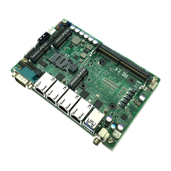
Page 8: Layout Diagram
1* Front panel header 1* Speaker & Power LED header 1* LAN LED activity header 1* RS232 serial port header (COM2, RS232/RS422/485) 1* GPIO_CON header 1* 9-pin USB 2.0 header (Expansible to 2* USB 2.0 ports) ... - Page 9 Motherboard Internal Diagram-Front Side SATAIII Port Front Panel PS/2 Keyboard SATA HDD Header & Mouse Header USB 2.0 HDMI Header Power Connector Header USB 2.0 Header SMBUS Header Serial Port RS232 Serial Port Header Speaker & PWRLED Header GPIO Header Half-size Mini-PCIE Slot (MPE2) LAN1...
- Page 10 COPEN Jumper Position: JBAT_ MERTC AT_MODE JPCOM2 Jumper Jumper Name Description Pitch JPCOM2 COM2 Header Pin9 Function Select 4-Pin Block 2.0mm AT_MODE ATX Mode / AT Mode Select 3-Pin Block 2.54mm COPEN Case Open Message Display Function 2-Pin Block 2.54mm JBAT_MERTC Pin 1&2: Clear CMOS 6-Pin Block 2.0mm...
- Page 11 Connectors Name Connector DCIN 12V System DC–in Power Jack Connector USB1 USB 3.0 Port Connector X2 LAN1/2/3/4 RJ-45 LAN Port Connector x 4 COM1 Serial Port Connector ATX2P Internal 12V System DC–in Power Connector CPUFAN CPU Fan Connector SATA1 SATAIII Port Connector STATPWR SATA Power out Connector Headers...
-
Page 12: Chapter 2 Hardware Installation
Chapter 2 Hardware Installation 2-1 Jumper Setting JPCOM2 (4-pin): COM2 Header Pin9 Function Select Pitch=2.0mm JPCOM2 COM2 Header Pin-9 2 4 6 2 4 6 1 3 5 1 3 5 JPCOM2 2-4 Closed: 4-6 Closed: 3-4 Closed: RING( Default); 12V. - Page 13 COPEN (2-pin): Case Open Message Display Function Select Pitch=2.54mm COPEN 1-2 Open: 1-2 Short: Normal (Default); Case Open. Pin (1-2) Close: When Case Open function pin short to GND, the Case Open function was detected. When Used, needs to enter BIOS and enable ‘Case Open Detect’ function.
- Page 14 Pin 3&4 of JBAT_MERTC (6-pin): Flash Override Function Slect Pitch=2.0mm JBAT_MERTC Pin 5&6 of JBAT_MERTC (6-pin): POK Override Function Slect Pitch=2.0mm JBAT_MERTC...
-
Page 15: Connectors And Headers
Connectors and Headers 2-2-1 Connectors (1) Rear I/O Connectors 2.5Gbps RJ-45 12V DC-in LAN Port Power Connector 1.0Gbps RJ-45 RS232 Serial Port LAN Port USB 3.0 Ports Icon Name Function For user to connect compatible power 12V DC-in Power adapter to provide power supply for the Connector system. - Page 16 (2) ATX2P (2-pin Block): Internal 12V DC-in Power Connector Warning!! The board has a 12V DC-in power connector (DC_IN) in I/O back panel and an internal ATX2P (ATXPWR) power connector. User can only connect one type of compatible power supply to one of them to power the system. (3) SATA1 (7-pin Block): SATAIII Port connector SATA1 port is a high-speed SATAIII port that supports 6GB/s transfer rate.
- Page 17 (4) SATAPW (4-pin): SATA Power Out Connector SATAPW Warning: Make sure that Pin-1 of compatible SATA Power connector is inserted into corresponding Pin-1 of SATAPW to avoid possible damage to the board and hard disk driver! (5) CPUFAN (4-pin): CPUFAN Connector CPUFAN...
-
Page 18: Headers
2-2-2 Headers (1) JW_FP (9-pin): Front Panel Header Pitch=2.54mm JW_FP (2) SPK-LED (8-pin): Speaker & Power LED Header Pitch=2.0mm SPK-LED... - Page 19 (3) LAN_LED (8-pin): LAN Activity LED Header Pitch=2.0mm LAN_LED (4) COM2 (9-pin): RS232/422/485 Serial Port Header Pitch=2.0mm 6 7 8 9 3 4 5 Pin 1 *Notice: COM2 servers as RS232 serial port header in most cases.RS422 & RS485 function is only optional to customized models. User also needs to go to BIOS to set ‘Transmission Mode Select’...
- Page 20 support RS422/485 function before connecting compatible COM cable to COM2 header. (5) GPIO_CON (10-pin): GPIO Header Pitch=2.0mm Pin 1 GPIO_CON (6) FP_USB1 (9-pin): USB 2.0 Port Header Pitch=2.0mm Pin 1 FP_USB1...
- Page 21 (7) FP_USB2 (4-pin): USB 2.0 Port Header Pitch=2.54mm FP_USB2 Pin 1 (8) SMBUS (5-Pin): SMBUS Header Pitch=2.54mm SMBUS...
- Page 22 (9) PS2KBMS (6-pin): PS2 Keyboard & Mouse Port Header Pitch=2.54mm PS2KBMS (10) HDMI (19-pin): HDMI Port Header Pitch=2.0mm HDMI_HPD HDMI HDMI_+5V HDMI_SDA HDMI_SCL HDMI_TXCN HDMI_TXN0 HDMI_TXCP HDMI_TXP0 HDMI_TXN1 HDMI_TXN2 HDMI_TXP1 HDMI_TXP2 Pin 1...
-
Page 23: Chapter 3 Introducing Bios
Chapter 3 Introducing BIOS Notice! The BIOS options in this manual are for reference only. Different configurations may lead to difference in BIOS screen and BIOS screens in manuals are usually the first BIOS version when the board is released and may be different from your purchased motherboard. Users are welcome to download the latest BIOS version form our official website. -
Page 24: Bios Menu Screen
BIOS Menu Screen The following diagram show a general BIOS menu screen: Menu Bar General Help Items Current Setting Value Menu Items Function Keys Function Keys In the above BIOS Setup main menu of, you can see several options. We will explain these options step by step in the following pages of this chapter, but let us first see a short description of the function keys you may use here: ... -
Page 25: Getting Help
Press <+>/<–> keys when you want to modify the BIOS parameters for the active option. [F1]: General help. [F2]: Previous value. [F3]: Optimized defaults. [F4]: Save & Exit. [F7]: To enter pop-up boot menu to select boot device. ... -
Page 26: Main Menu
Main Menu Main menu screen includes some basic system information. Highlight the item and then use the <+> or <-> and numerical keyboard keys to select the value you want in each item. System Date Set the date. Please use [Tab] to switch between data elements. System Time Set the time. -
Page 27: Advanced Menu
3-7 Advanced Menu CPU Configuration Press [Enter] to view current CPU configuration and make settings for the following sub-items: Intel Virtualization Technology The optional settings: [Enabled]; [Disabled]. When set as [Enabled], a VMM can utilize the additional hardware capabilities provided by Vanderpool Technology. - Page 28 Adjacent Cache Line Prefetch The optional settings are: [Disabled]; [Enabled]. Use this item to turn on/off prefetching of adjacent cache lines. Intel(R) SpeedStep(tm) Use this item to Allows more than two frequency ranges to be supported The optional settings: [Disabled]; [Enabled]. CPU C States Use this item to enable or disable CPU Power Management.
- Page 29 The optional settings are: [Enabled]; [Disabled]. Hot Plug Use this item to designates this port as Hot Pluggable The optional settings are: [Enabled]; [Disabled]. PCH-FW Configuration Press [Enter] to view ME information and make settings in the following sub-items: TPM Device Selection Use this item to select TPM device: PTT or dTPM.
- Page 30 ACPI Sleep State Use this item to select the highest ACPI sleep state the system will enter when the suspend button is pressed. The optional settings are: [Suspend Disabled]; [S3 (Suspend to RAM)]. Wake-up Function Settings Press [Enter] to make settings for the following sub-items: Wake-up System with Fixed Time Use this item to enable or disable system wake on alarm event.
- Page 31 Press [Enter] to make settings for the following sub-items: Super IO Configuration ERP Support Use this item to energy-related products function. The optional settings: [Disabled]; [Auto]. This item should be set as [Disabled] if you wish to have all active wake-up functions.
- Page 32 Transmission Mode Select The optional settings are: [RS422]; [RS232]; [RS485]. Mode Speed Select The optional settings are: [RS232/RS422/RS485=250kbps]; [RS232=1Mbps, RS422/RS485=10Mbps]. Serial Port FIFO Mode The optional settings are: [16-Byte FIFO]; [32-Byte FIFO]; [64-Byte FIFO]; [128-Byte FIFO]. WatchDog Reset Timer Use this item to enable or disable WDT reset function. When set as [Enabled], the following sub-items shall appear: WatchDog Reset Timer Value User can set a value in the range of [4] to [255].
- Page 33 Case Open Detect Use this item to detect case has already open or not, show message in POST. The optional settings: [Disabled]; [Enabled]. When set as [Enabled], system will detect if COPEN has been short or not (refer to Page 8); if Pin 1&2 of COPEN is short, system will show Case Open Message during POST.
- Page 34 The optional settings are: [Disabled]; [70°C/158°F]; [75°C/167°F]; [80°C/176°F]; [85°C/185°F]; [90°C/194°F]. Serial Port Console Redirection Press [Enter] to make settings for the following sub-items: COM1 Console Redirection Use this item to enable or disable COM1 Console Redirection. The optional settings are: [Disabled]; [Enabled]. When set as [Enabled], user can make further settings in the ‘Console Redirection Settings’...
- Page 35 [Odd]: parity bit is 0 if num of 1’s in the data bits is odd. [Mark]: parity bit is always 1. [Space]: parity bit is always 0. Mark and Space Parity do not allow for error detection. The optional settings are: [None]; [Even]; [Odd];[Mark]; [Space]. Stop Bits Use this item to stop bits indicate the end of a serial data packet.
- Page 36 Putty Keypad Use this item to select functionkey and keypad on putty The optional settings are: [VT100]; [LINUX]; [XTERMR6]; [SCO]; [ESCN]; [VT400]. Redirection After BIOS POST Use this item to the settings specify if BootLoader is selected then Legacy console redirection is disabled before booting to Legacy OS. Default value is always enable which means legaacy console redirection is enabled for legacy The optional settings are: [Always Enable];...
- Page 37 Use this item to selects serial port transmission speed. The speed must be matched on the other side. Long or noisy lines may require lower speeds. The optional settings are: [9600]; [19200]; [57600]; [115200]. Flow Control Use this item to flow control can prevent data loss from buffer overflow. When sending data, if the receiving buffers are full, a ‘stop’...
- Page 38 HTTP boot option will not be created. Ipv6 PXE Support The optional settings are: [Disabled]; [Enabled]. Use this item to enable Ipv6 PXE Boot Support. When set as [Disabled], Ipv6 boot optional will not be created. Ipv6 HTTP Support The optional settings are: [Disabled]; [Enabled]. Use this item to enable Ipv6 HTTP Boot Support.
- Page 39 The optional settings are: [Enabled]; [Disabled]; [Auto]. [Enabled]: To enable legacy USB support. [Disabled]: To keep USB devices available only for EFI specification, [Auto]: To disable legacy support if no USB devices are connected. XHCI Hand-off This is a workaround for OSes without XHCI hand-off support. The XHCI ownership change should be claimed by XHCI driver.
-
Page 40: Chipset Menu
Intel(R) Ethernet Controller I225-V - XX:XX:XX:XX:XX:XX These items show current networks’ information Intel(R) Ethernet Connection (3) I219-LM - XX:XX:XX:XX:XX:XX These items show current networks’ information 3-8 Chipset Menu System Agent (SA) Configuration Press [Enter] to make settings for the following sub-items: VT-d Use this item to enable or disable VT-d capability. - Page 41 Graphics Configuration ▶ Press [Enter] to for user to view IGFX basic information or make further settings for graphics configuration. Graphics Configuration GTT Size The optional settings are: [2MB];[4MB];[8MB]. Aperture Size Use this item to select the aperture size The optional settings are: [128MB]; [256MB]; [512MB]; [1024MB]. *Note: Above 4GB MMIO BIOS assignment is automatically enabled when selecting 2048MB aperture.
- Page 42 Use this item to enable or disable this USB physical connector (physical port). Once disabled, any USB devices plugged into this connector will not be detected by BIOS or OS. The optional settings are: [Disabled]; [Enabled]. Onboard Lan1 Controller Use this item to enable or disable Lan1 onboard NIC. The optional settings are: [Enabled];...
-
Page 43: Security Menu
3-9 Security Menu Security menu allow users to change administrator password and user password settings. Administrator Password Press [Enter] to create new administrator password. Press again to confirm the new administrator password. User Password Press [Enter] to create new user password. Press again to confirm the new user password. -
Page 44: Boot Menu
3-10 Boot Menu Boot Configuration Setup Prompt Timeout Use this item to set number of seconds to wait for setup activation key. Bootup Numlock State Use this item to select keyboard numlock state. The optional settings are: [On]; [Off]. Quiet Boot The optional settings are: [Disabled];... -
Page 45: Save & Exit Menu
The optional settings are: [UEFI: Built-in EFI Shell]; [Disabled]. UEFI Boot The optional settings are: [Disabled]; [Enabled]. [Enabled]: To enable all UEFI boot options. [Disabled]:To disabled all UEFI boot options. 3-11 Save & Exit Menu Save Options Save Changes and Reset This item allows user to reset the system after saving the changes. - Page 46 Default Options Restore Defaults Use this item to restore /load default values for all the setup options. Save as User Defaults Use this item to save the changes done so far as user defaults. Restore User Defaults Use this item to restore defaults to all the setup options. Boot Override UEFT: Built-in EFI Shell Launch Internal EFI shell application (shell.efi).