Pioneer MVH-290BT Service Manual
Digital media receiver
Hide thumbs
Also See for MVH-290BT:
- Owner's manual (60 pages) ,
- Owner's manual (22 pages) ,
- Owner's manual (20 pages)
Table of Contents
Advertisement
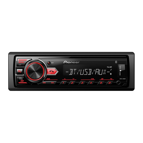
DIGITAL MEDIA RECEIVER
MVH-290BT
MVH-291BT
MVH-29BT
MVH-295BT
PIONEER CORPORATION
PIONEER ELECTRONICS (USA) INC. P.O. Box 1760, Long Beach, CA 90801-1760, U.S.A.
PIONEER EUROPE NV Haven 1087, Keetberglaan 1, 9120 Melsele, Belgium
PIONEER ELECTRONICS ASIACENTRE PTE. LTD. 2 Jalan Kilang Barat, #07-01, Singapore 159346
PIONEER CORPORATION 2016
28-8, Honkomagome 2-chome, Bunkyo-ku, Tokyo 113-0021, Japan
MVH-290BT/XEUC
/XEUC
/XEUW5
/XEES
ORDER NO.
CRT5946
/XEUC
K-ZZZ AUG. 2016 Printed in Japan
Advertisement
Table of Contents

Related Manuals for Pioneer MVH-290BT


Summary of Contents for Pioneer MVH-290BT
- Page 1 PIONEER CORPORATION 28-8, Honkomagome 2-chome, Bunkyo-ku, Tokyo 113-0021, Japan PIONEER ELECTRONICS (USA) INC. P.O. Box 1760, Long Beach, CA 90801-1760, U.S.A. PIONEER EUROPE NV Haven 1087, Keetberglaan 1, 9120 Melsele, Belgium PIONEER ELECTRONICS ASIACENTRE PTE. LTD. 2 Jalan Kilang Barat, #07-01, Singapore 159346 PIONEER CORPORATION 2016 K-ZZZ AUG.
-
Page 2: Table Of Contents
10.2 MAIN BOARD PCB (TUN/ASP/AMP) ....................19 10.3 MAIN BOARD PCB (POWER/INTERFACE) ..................20 10.4 KEY PCB ............................... 21 11. PCB CONNECTION DIAGRAM ........................22 11.1 MAIN BOARD PCB ..........................22 11.2 KEY PCB ............................... 24 12. ELECTRICAL PARTS LIST .......................... 25 MVH-290BT/XEUC... -
Page 3: Service Precautions
For environmental protection, lead-free solder is used on the printed circuit boards mounted in this unit. Be sure to use lead-free solder and a soldering iron that can meet specifications for use with lead-free solders for repairs accompanied by reworking of soldering. MVH-290BT/XEUC... -
Page 4: Specifications
2.2 DISC/CONTENT FORMAT The Bluetooth word mark and logos are owned by the Bluetooth SIG, Inc. and any use of such marks by Pioneer Corporation is under license. Other trademarks and trade names are those of their respective owners. 3. BASIC ITEMS FOR SERVICE 3.1 CHECK POINTS AFTER SERVICING... -
Page 5: Block Diagram
BLOCK DIAGRAM MCU FLASH BT FLASH MAIN BOARD PCB KEY PCB GPIO EXPANDER FM/AM ANT TN LCD Radio Tune LCD101 I 2C LCD Driver LINE OUT/ IC401 MPEG EN100 AUX IN CON102 UART AMPLIFIER BT MODULE CON103 U403 U500 CONNECTION DIAGRAM MAIN BOARD PCB KEY PCB Signal name... -
Page 6: Power Supply System Figure
POWER SUPPLY SYSTEM FIGURE BATT CONT/A.ANT 75 mA LDO 5.78V MPEG EMP8965 3.3V 100 mA 50 mA 1N4004 I/O EXP 1N4004 310 mA U101 BT MODULE U500 EUP3482A 3 300 uF TUNER 160 mA 2 200 uF 500 mA U403 LAMP 200 mA LCD DRIVER... -
Page 7: Diagnosis
When the detach grill is mounted on each unit, the function is followed by the unit on that. You can use this in case of troubleshooting if necessary. [New one] [Conventional one] MVH-290BT/XEUC, MVH-291BT/XEUC, MVH-29BT/XEUW5, MVH-08UBG/XEUW5, MVH-08UB/XEUW5, MVH-85UB/XEES, MVH-295BT/XEES MVH-88UB/XFBR USB storage device is not recognized. - Page 8 In case of no signal: The cause should be microphone factor In case of correct signal: Replace the product (otherwise MBL CMPX MODULE if it is available). (Check point) Check point of MIC-P (One side of R516) Check point of MIC-N (One side of R517) MVH-290BT/XEUC...
-
Page 9: Error Code List
ACC or ON. The connected USB device is not supported by this unit. – Disconnect your device and replace it with a compatible USB device. HUB ERROR The USB device connected via a USB hub is not supported by this unit. MVH-290BT/XEUC... -
Page 10: Connector Function Description
10 NC 3 FL- 11 MCU_RXD 4 FR- 12 NC 13 ACC 5 RL+ 14 B_REM 6 RR+ 7 RL- 15 BAT+ 8 RR- 16 DGND1 6. SERVICE MODE There is not information to be shown in this chapter. MVH-290BT/XEUC... -
Page 11: Disassembly
Main Frame Main Board Assy Board Assy. Fig.2 - Removing the Main Board PCB (Fig.3) Main Board PCB Remove the two screws. Straighten the tab at location indicated and then remove the Main Board PCB. Fig.3 MVH-290BT/XEUC... - Page 12 1. Attach the spike from the front side of the cabinet. Fig.6 2. Attach the spring to the lock as shown in the figure. The bended tip of the spring is set to this side. Hitch the spring to the groove. Fig.7 MVH-290BT/XEUC...
-
Page 13: Each Setting And Adjustment
Fig.8 8. EACH SETTING AND ADJUSTMENT There is not information to be shown in this chapter. MVH-290BT/XEUC... -
Page 14: Exploded Views And Parts List
Screw adjacent to mark on the product are used for disassembly. For the applying amount of lubricants or glue, follow the instructions in this manual. (In the case of no amount instructions,apply as you think it appropriate.) 9.1 PACKING MVH-291BT/XEUC MVH-290BT/XEUC... - Page 15 See Contrast table (2) Polyethylene Bag 127060020025 Screw(M5 x 7) See Contrast table (2) (2) CONTRAST TABLE MVH-290BT/XEUC, MVH-291BT/XEUC, MVH-29BT/XEUW5 and MVH-295BT/XEES are constructed the same except for the following: Mark Description MVH-290BT/XEUC MVH-291BT/XEUC MVH-29BT/XEUW5 MVH-295BT/XEES Screw(M2 x 6) 121045000007...
-
Page 16: Exterior
9.2 EXTERIOR MVH-290BT/XEUC... - Page 17 Screw 121106070013 Knob 121230005747000 MBL CMPX MODULE See Contrast table (2) Spike 121200001032000 (2) CONTRAST TABLE MVH-290BT/XEUC, MVH-291BT/XEUC, MVH-29BT/XEUW5 and MVH-295BT/XEES are constructed the same except for the following: Mark Description MVH-290BT/XEUC MVH-291BT/XEUC MVH-29BT/XEUW5 MVH-295BT/XEES Detachable Assy 845CRB1299WAKB000 845CRB1299WMKB000 845CRB1299WUKB000...
-
Page 18: Schematic Diagram
10. SCHEMATIC DIAGRAM Note: When ordering service parts, be sure to refer to " EXPLODED VIEWS AND PARTS LIST" . MAIN BOARD PCB (MPEG/DECT) EEPROM S3V3 MCU+MPEG NC(FT24C16A-USR-T) 10uF S3V3 MP3_R 10uF R308 MP3_L I2C_SCL S1V2 S3V3 S3V3 ACC+DTH I2C_SDA 1.8nF 1.8nF ACC_DECT... -
Page 19: Main Board Pcb (Tun/Asp/Amp)
MAIN BOARD PCB (TUN/BT/ASP/AMP) C119 2.2uF R114 4.7K TUNER_R 4.7K C2 2.2uF TUNER_L PreOUT+SUBOUT T101 120K 4.000M R366 TU_GND EC23 C123 C148 C109 C108 4.7K 3300uF,25V 100nF 4.7uF,16V 820R Tuner TU_GND STBY TU_GND PGND 10uH/0.45A DTC643 10uF R365 KRA102S H-SW/OFFSET B.REM FM/AM OPTION(160713) -
Page 20: Main Board Pcb (Power/Interface)
MAIN BOARD PCB (POWER/INTERFACE) S3V3 S5V78 B+_5V 10nF MAX: 420mA S1V2 TUN_3V3 L101 L102 100R 10uH/1.42A 33uH,÷20%,3A KTC8550S KTC8550S KTC8550S KTC8050S U11 SA1117-ADJ EMP8965 4.7R 3 VIN VOUT 100R R500 U101 1N5404 M4D,400V/1A MAX: 80mA MAX: 310mA EUP3482A GND/ADJ R110 7 EN POWER_EN R107... -
Page 21: Key Pcb
KEY PCB LCD101 LCD-TN-N82207MS-CM1299-56P-AA MARK CON101 KEY0 DGND AUX-GND AUX_R AUX_L USB_GND KEY2 EN_B LCD_SCE LCD_SCL KEY1 LCD_SDI EN_A LAMP PANEL_DET SG33 SG16 SG34 SG15 SG35 SG14 DGND SG36 SG13 SG37 SG12 SG38 SG11 SG39 IC401 SG10 SG40 SG09 BU97510KV SG41 SG08 CON102... -
Page 22: Pcb Connection Diagram
11. PCB CONNECTION DIAGRAM SIDE A MAIN BOARD PCB NOTE FOR PCB DIAGRAMS 1.The parts mounted on this PCB include all necessary parts for several destination. For further information for respective destinations, be sure to check with the schematic dia- gram. - Page 23 SIDE B MAIN BOARD PCB...
-
Page 24: Key Pcb
SIDE A KEY PCB DISP POWER/SRC PHONE SEARCH ENCODER BAND SEEK- SEEK+ 1/UP 2/DN 4/PLAY 5/RDM 6/RPT SIDE B KEY PCB... -
Page 25: Electrical Parts List
The expression of the unit in this manual is shown by u instead of . Please do not make a mistake. Circuit Symbol and No. Part No. Unit Number : Unit Name : MAIN BOARD PCB Unit Number : Unit Name : MAIN BOARD PCB MISCELLANEOUS Power Amp IC PA2032A Poly Switch 144800010012 EN100 Rotary Encoder 121658000198 MVH-290BT/XEUC...