Advertisement
Quick Links
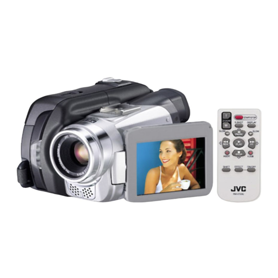
SERVICE MANUAL
4
2005
YF091
GR-DF540EX, GR-DF540EY,
GR-DF540EZ, GR-DF565EX,
GR-DF570EK, GR-DF570EX,
GR-DF570EY, GR-DF570EZ
For disassembling and assembling of MECHANISM ASSEMBLY, refer to the SERVICE MANUAL No.86700(MECHANISM ASSEMBLY).
1
PRECAUTIONS . . . . . . . . . . . . . . . . . . . . . . . . . . . . . . . . . . . . . . . . . . . . . . . . . . . . . . . . . . . . . . . . . . . . . . . 1-3
2
SPECIFIC SERVICE INSTRUCTIONS . . . . . . . . . . . . . . . . . . . . . . . . . . . . . . . . . . . . . . . . . . . . . . . . . . . . . . 1-5
3
DISASSEMBLY . . . . . . . . . . . . . . . . . . . . . . . . . . . . . . . . . . . . . . . . . . . . . . . . . . . . . . . . . . . . . . . . . . . . . . . 1-6
4
ADJUSTMENT . . . . . . . . . . . . . . . . . . . . . . . . . . . . . . . . . . . . . . . . . . . . . . . . . . . . . . . . . . . . . . . . . . . . . . . 1-17
5
TROUBLE SHOOTING . . . . . . . . . . . . . . . . . . . . . . . . . . . . . . . . . . . . . . . . . . . . . . . . . . . . . . . . . . . . . . . . . 1-20
DIGITAL VIDEO CAMERA
TABLE OF CONTENTS
COPYRIGHT © 2005 Victor Company of Japan, Limited
GR-DF540EXM, GR-DF540EYM,
GR-DF540EZM, GR-DF565EXM[M5D5S8],
GR-DF570EKM, GR-DF570EXM, GR-DF570EYM,
GR-DF570EZM[M5D5S9]
No.YF091
2005/4
Advertisement

Related Manuals for JVC GR-DF540EX


Summary of Contents for JVC GR-DF540EX
-
Page 1: Table Of Contents
SERVICE MANUAL DIGITAL VIDEO CAMERA YF091 2005 GR-DF540EX, GR-DF540EY, GR-DF540EZ, GR-DF565EX, GR-DF570EK, GR-DF570EX, GR-DF570EY, GR-DF570EZ GR-DF540EXM, GR-DF540EYM, GR-DF540EZM, GR-DF565EXM[M5D5S8], GR-DF570EKM, GR-DF570EXM, GR-DF570EYM, GR-DF570EZM[M5D5S9] For disassembling and assembling of MECHANISM ASSEMBLY, refer to the SERVICE MANUAL No.86700(MECHANISM ASSEMBLY). TABLE OF CONTENTS PRECAUTIONS . - Page 2 SPECIFICATION Camcorder For General Power supply DC 11.0 V(Using AC Adapter) DC 7.2 V (Using battery pack) Power consumption Approx. 3.7 W(4W*)(LCD monitor off, viewfinder on) Approx. 4.7W (5W*)(LCD monitor on, viewfinder off) * Using LED Light Dimensions (W × H × D) 75 mm ×...
-
Page 3: Precautions
SECTION 1 PRECAUTIONS SAFTY PRECAUTIONS Prior to shipment from the factory, JVC products are strictly emission. Consequently, when servicing these products, inspected to conform with the recognized product safety and replace the cathode ray tubes and other parts with only the electrical codes of the countries in which they are to be specified parts. - Page 4 1.1.2 Safety Check after Servicing Examine the area surrounding the repaired location for damage (4) Leakage current test or deterioration. Observe that screws, parts and wires have been Confirm specified or lower leakage current between earth returned to original positions, Afterwards, perform the following ground/power cord plug prongs and externally exposed tests and confirm the specified values in order to verify accessible parts (RF terminals, antenna terminals, video...
-
Page 5: Specific Service Instructions
SECTION 2 SPECIFIC SERVICE INSTRUCTIONS DIFFERENCE LIST The following table indicate main different points between models GR-DF540EX, GR-DF540EY, GR-DF540EZ, GR-DF565EX, GR-DF570EK, GR-DF570EX, GR-DF570EY and GR-DF570EZ. MODEL NAME GR-DF540EX GR-DF540EY GR-DF540EZ GR-DF565EX MEMORY CARD DV TERMINAL YES(OUT) YES(OUT) YES(OUT) YES(OUT) ANALOG INPUT... -
Page 6: Disassembly
SECTION 3 DISASSEMBLY BEFORE ASSEMBLY AND DISASSEMBLY 3.1.4 Tools required for disassembly and assembly 3.1.1 Precautions Torque driver Tweezers YTU94088 • Be sure to disconnect the power supply unit prior to mounting YTU94088-003 P-895 and soldering of parts. • Prior to removing a component part that needs to disconnect its connector(s) and its screw(s), first disconnect the wire(s) from the connector(s), and then remove the screw(s). - Page 7 3.2.2 ASSEMBLY/DISASSEMBLY OF CABINET PARTS AND ELECTRICAL PARTS Disassembly procedure NOTE11b: STEP Fig. During the procedure, leave the CASSETTE COVER (C. POINT NOTE PART COVER) open. COVER(JIG CON) S1a,S1b,JACK COVER(DV) NOTE1a,b,c NOTE11c: COVER(TOP) ASSY S2,L2 When disassembling, be careful in handling the JACK COV- SHOE 3(S3) ER (MIC) as it comes off together.
- Page 8 <NOTE1b> <BOTTOM VIEW> (S3) NOTE1a JACK (S3) (S3) COVER (S4) (DV) (S1b) (S1a) (S1b) NOTE1b (S4) (S2) JACK COVER(DV) NOTE4 CASSETTE COVER (S4) (S4) NOTE1c (S4) (S4) Fig.FA1 Fig.FA2 <BOTTOM VIEW> <NOTE5> JACK (S5a) (S5a) COVER(DC) (S5b) (S5a) NOTE5 (S5c) (S5c) (S5b) (S5d)
- Page 9 NOTE6a NOTE6b (S6a) (S6a) (S7) <BOTTOM VIEW> <WIRING> (S7) (S6b) NOTE7 (S6b) (FRONT) (S6b) NOTE6b (S6b) WIRE(MIC) Fig.FA4 NOTE8 (S8a) (S8b) (S8c) (S8c) Fig.FA5 (No.YF091)1-9...
- Page 10 CN9b NOTE11a GRIP BELT CN9a [12] L12b NOTE11b [11] L12a (S12) (S11a) CN9b (S11b) JACK COVER(MIC) CN9a NOTE11c EJECT SW (S11a) NOTE12 (S11a) (S9) (S9) Fig.FA6 Fig.FA8 <NOTE13b> <NOTE10c> CN13b SENSOR FPC WIRE [10] L13b [13] (S10) CN10b (S10) CN13a L13c (S10) HEAT SINK1...
- Page 11 [15] NOTE15 BKT(MECHA) ASSY (S15b) (S15b) CN14d (S15b) (S15a) [14] (S14) BKT(PRE-REC) (S14) CN14a CN14b CN14c : 0.059N m (0.6kgf cm) Fig.FA10-1 <NOTE15> LOADING MOTOR <WIRING> Fig.FA10-2 (No.YF091)1-11...
- Page 12 3.2.3 DISASSEMBLY of [8] UPPER ASSEMBLY [16] Removing VF ASSEMBLY (1) Remove the FPC from the connector (CN8a). [17] (2) Remove the three screws (1-3), and remove the VF AS- (S8c) SEMBLY. (S8c) NOTE8a: During the procedure, be careful not to break the FPC. [17] Removing MONITOR ASSEMBLY (1) Remove the screw (4).
- Page 13 3.2.4 DISASSEMBLY of [9] OP BLOCK ASSMBLY/CCD BOARD ASSEMBLY CAUTIONS Assembly of OP BLOCK ASSEMBLY/ CCD BOARD AS- (1) During the procedure, be careful in handling the CCD SEMBLY IMAGE SENSOR, OP LPF, and lens components. (1) Assemble the OP BLOCK ASSEMBLY in order, first with Pay special attention not to soil, dust, or scratch the sur- the OP LPF then with the SHEET.
- Page 14 3.2.5 DISASSMBLY of [16] VF ASSEMBLY Before disassembly As the VF ASSEMBLY has complicated structure, do not dis- NOTE16a,b assemble if not needed. GUIDE(VF) Inside the VF is divided into two units: LCD ASSEMBY / LENS ASSEMBY, and each unit is made up of several parts. Disas- (S16a) semble the VF ASSEMBLY if necessary.
- Page 15 NOTE16d KNOB(ADJ) <LCD ASSY> <NOTE16d,e> CASE (UPPER) CASE(B.LIGHT) NOTE16d NOTE16h LENS ASSY SHEET(DIFF.) NOTE16g LCD ASSY L16p NOTE16h SHEET(POLA.1) COVER L16q (LENS) CN16a CUSHION(LCD) VF BOARD ASSY L16k NOTE16f CASE(LOWER) NOTE16h LCD MODULE L16m L16n Fig.VF3 GUIDE(LCD) HOLDER(LCD) L16u L16s L16t L16r NOTE16h...
- Page 16 3.2.6 DISASSEMBLY of [17] MONITOR ASSEMBLY <NOTE17a> <NOTE17c> L17c Disassembly of MONITOR ASSEMBLY L17d (1) Remove the three screws (1-4), and remove the MONI- TOR COVER ASSEMBLY by disengaging the five hooks (L17a-e). NOTE17a: When removing, be careful not to damage the hooks. L17a L17b (2) Pull out the U/D SWITCH BOARD from the MONITOR...
-
Page 17: Adjustment
SECTION 4 ADJUSTMENT PREPARATION 4.1.3 TOOLS REQUIRED FOR ADJUSTMENT 4.1.1 Precaution Torque Driver Tweezers YTU94088 YTU94088-003 P-895 Camera system and deck system of this model are specially adjusted by using PC. However, if parts such as the following are replaced, an adjustment is required. - Page 18 • Chip IC replacement jig JIG CONNECTOR CABLE CONNECTION To be used for adjustment of the camera system. Connection procedure • Cleaning cloth Recommended the Cleaning cloth to wipe down the video heads, mechanism (tape transport system), optical lens sur- face.
- Page 19 Jig connector diagrams MECHANISM COMPATIBILITY ADJUSTMENT 4.3.1 Tape pattern adjustment JIG CONNECTOR CABLE (YTU93106C) NOTE: Prior to the adjustment, remove the COVER (ADJ). MAIN CN113 (1) Play back the compatibility adjustment tape. (2) While triggering the HID, observe the waveform of EXMOD_1 NOTE: SYS_TMS...
-
Page 20: Trouble Shooting
SECTION 5 TROUBLE SHOOTING SERVICE NOTE 1-20 (No.YF091) - Page 21 EMERGENCY DISPLAY Example (in case of the error number E01): Whenever some abnormal signal is input to the syscon CPU, an error number (E01, as an example) is displayed on the LCD monitor or (in the electronic view finder).In every error status, UNIT IN REMOVE AND such the message as shown below alter nately appear over and...
- Page 22 Victor Company of Japan, Limited AV & MULTIMEDIA COMPANY CAMCORDER CATEGORY 12, 3-chome, Moriya-cho, kanagawa-ku, Yokohama, kanagawa-prefecture, 221-8528, Japan (No.YF091) Printed in Japan...