Sharp LC-32SH20U Service Manual
Lcd color television
Hide thumbs
Also See for LC-32SH20U:
- Brochure (2 pages) ,
- Operation manual (46 pages) ,
- Service manual (83 pages)
Table of Contents
Advertisement
Quick Links
All manuals and user guides at all-guides.com
In the interests of user-safety (Required by safety regulations in some countries) the set should be restored
to its original condition and only parts identical to those specified should be used.
•
SERVICING NOTICES ON CHECKING ..............................................................................
•
HOW TO ORDER PARTS ....................................................................................................
•
IMPORTANT .........................................................................................................................
•
ABOUT LEAD FREE SOLDER (PbF) ..................................................................................
•
GENERAL SPECIFICATIONS ..............................................................................................
•
DISASSEMBLY INSTRUCTIONS ........................................................................................
•
SERVICE MODE LIST ..........................................................................................................
•
WHEN REPLACING EEPROM (MEMORY) IC ....................................................................
•
RE-WRITE FOR DIGITAL SOFT FIRMWARE .....................................................................
•
ELECTRICAL ADJUSTMENTS ............................................................................................
•
TROUBLESHOOTING GUIDE .............................................................................................
•
BLOCK DIAGRAM ................................................................................................................
•
PRINTED CIRCUIT BOARDS ..............................................................................................
•
SCHEMATIC DIAGRAMS ....................................................................................................
•
WAVEFORMS ......................................................................................................................
•
MECHANICAL EXPLODED VIEWS .....................................................................................
•
REPLACEMENT PARTS LIST .............................................................................................
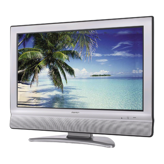
LCD COLOR TELEVISION
LC-32SH20U
MODEL
CONTENTS
This document has been published to be used for
after sales service only.
The contents are subject to change without notice.
#########
Page
A2-1~A2-5
B1-1~B2-2
C-1
C-2
C-3
F-1~F-10
H-1~H-52
K1-1~K2-11
Advertisement
Table of Contents

Related Manuals for Sharp LC-32SH20U


Summary of Contents for Sharp LC-32SH20U
-
Page 1: Table Of Contents
All manuals and user guides at all-guides.com ######### LCD COLOR TELEVISION LC-32SH20U MODEL In the interests of user-safety (Required by safety regulations in some countries) the set should be restored to its original condition and only parts identical to those specified should be used. -
Page 2: Servicing Notices On Checking
All manuals and user guides at all-guides.com SERVICING NOTICES ON CHECKING 1. KEEP THE NOTICES PERFORM A SAFETY CHECK AFTER SERVICING As for the places which need special attentions, they are indicated with the labels or seals on the Confirm that the screws, parts and wiring which cabinet, chassis and parts. -
Page 3: About Lead Free Solder (Pbf)
All manuals and user guides at all-guides.com ABOUT LEAD FREE SOLDER (PbF) Distinction of PbF PCB: PCBs (manufactured) using lead free solder will have a PbF printing on the PCB. (Please refer to figures.) Caution: • Pb free solder has a higher melting point than standard solder; Typically the melting point is 86°F~104°F(30°C~40°C) higher. -
Page 4: General Specifications
All manuals and user guides at all-guides.com GENERAL SPECIFICATIONS LCD Size / Visual Size 31.5 inch / 800.4mmV System LCD Type Color TFT LCD Number of Pixels 1366(H) x 768(V) View Range Left/Right 85/85 degree Up/Down 85/85 degree Color System NTSC Speaker 2 Speaker... - Page 5 All manuals and user guides at all-guides.com GENERAL SPECIFICATIONS Remote Unit RC-MQ Control Glow in Dark Remocon Remocon Format SHARP Format SHARP Custom Code 10000 / 10001 Power Source Voltage(D.C) UM size x pcs UM-3 x 2 pcs Total Keys...
- Page 6 All manuals and user guides at all-guides.com GENERAL SPECIFICATIONS G-10 Features Auto Shut Off Auto Search Power On Memory Comb Filter Game Position Auto Setup(Language/CH Program) Picture Setting(TV) AV Mode(Picture Preference) Brightness , Contrast , Color Tint Sharpness Color Temperature Cable Clear Picture Setting(PC) BRIGHTNESS , CONTRAST...
- Page 7 All manuals and user guides at all-guides.com GENERAL SPECIFICATIONS G-11 Accessories Owner's Manual Language English/French/Spanish w/Guarantee Card Remote Control Unit Rod Antenna Poles Terminal Loop Antenna Terminal U/V Mixer DC Car Cord (Center+) Guarantee Card Warning Sheet Circuit Diagram Antenna Change Plug Service Facility List Important Safeguard Dew/AHC Caution Sheet...
- Page 8 32(ORION SPEC:46) Container Stuffing (40' container) Sets/40' container G-16 Material Cabinet Front PS 94V0 NON-DECABROM Rear PS 94V0 NON-DECABROM Jack Panel Non-Halogen Demand Eyelet Demand G-17 Environment Environmental standard requirement Green procurement of SHARP Pb-free Phase3(Phase3A) Measures for Whisker Rohs A2-5...
-
Page 9: Disassembly Instructions
All manuals and user guides at all-guides.com DISASSEMBLY INSTRUCTIONS 1. REMOVAL OF MECHANICAL PARTS 1-3: PCB ASS'Y (Refer to Fig. 1-3) AND P.C. BOARDS Disconnect the following connectors: (CP506, CP507, CP508, CP510, CP511, CP512). 1-1: BACK CABINET (Refer to Fig. 1-1) Remove the 9 screws 1. - Page 10 All manuals and user guides at all-guides.com DISASSEMBLY INSTRUCTIONS 1-4: LCD COVER/LCD PANEL (Refer to Fig. 1-4) Remove the 8 screws 1. Remove the LCD Cover in the direction of arrow (A). Remove the 4 screws 2. Remove the LCD Panel in the direction of arrow (B). LCD Cover LCD Panel Front Cabinet...
- Page 11 All manuals and user guides at all-guides.com DISASSEMBLY INSTRUCTIONS REMOVAL AND INSTALLATION OF When IC starts moving back and forth easily after desoldering completely, pickup the corner of the IC using FLAT PACKAGE IC tweezers and remove the IC by moving with the IC desoldering machine.
- Page 12 All manuals and user guides at all-guides.com DISASSEMBLY INSTRUCTIONS INSTALLATION When bridge-soldering between terminals and/or the soldering amount are not enough, resolder using a Thin- Take care of the polarity of new IC and then install the tip Soldering Iron. (Refer to Fig. 2-8.) new IC fitting on the printed circuit pattern.
-
Page 13: Service Mode List
All manuals and user guides at all-guides.com SERVICE MODE LIST This unit is provided with the following SERVICE MODES so you can repair, examine and adjust easily. To enter to the SERVICE MODE function, press and hold both buttons simultaneously on the main unit and on the remote control for more than the standard time in the appropriate condition. -
Page 14: When Replacing Eeprom (Memory) Ic
All manuals and user guides at all-guides.com WHEN REPLACING EEPROM (MEMORY) IC CONFIRMATION OF CHECK SUM, POWER ON TOTAL HOURS, MICON VERSION AND DIGITAL TV MICON FIRMWARE Initial total of MEMORY IC, POWER ON total hours, MICON VERSION and Digital TV MICON Firmware can be checked on the screen. -
Page 15: Re-Write For Digital Soft Firmware
All manuals and user guides at all-guides.com RE-WRITE FOR DIGITAL SOFT FIRMWARE JG176 USA HD DTV ROM DISC Ref. No. Part No. Parts Name Remarks USA HD DTV ROM Up-Date of the Firmware JG176 APJG176095 DISC NOTE: The operating manual for Re-writing is included in USA HD DTV ROM DISC (JG176). Prepare the following tools for Up-Date of the Firmware. -
Page 16: Electrical Adjustments
All manuals and user guides at all-guides.com ELECTRICAL ADJUSTMENTS 1. ADJUSTMENT PROCEDURE FUNCTION FUNCTION H POSI OSD H POSI 60Hz Read and perform these adjustments when repairing the V POSI OSD V POSI 60Hz circuits or replacing electrical parts or PCB assemblies. R DRIVE (N) BAK LIGHT CENT CAUTION... - Page 17 All manuals and user guides at all-guides.com ELECTRICAL ADJUSTMENTS 2-2: Confirmation of Fixed Value (Step No.) Please check if the fixed values of each of the adjustment items are set correctly referring below. (TV/AV/CS/HD-MI) HD-MI AV (S) 480i 480p 720p 1080i 480i 480p...
- Page 18 All manuals and user guides at all-guides.com ELECTRICAL ADJUSTMENTS 3. ELECTRICAL ADJUSTMENT PARTS LOCATION GUIDE (WIRING CONNECTION) LCD PANEL DIGITAL PCB REMOCON PCB OS2200 CP512 CP2201 CP511 OPERATION PCB CP510 CP2203 CP507 AC IN CP508 CP506 POWER PCB J502 CP3803 CP4202 CP2200 CP3201...
-
Page 19: Troubleshooting Guide
All manuals and user guides at all-guides.com TROUBLESHOOTING GUIDE POWER DOES NOT TURN ON CHANGE F501. IS F501 BROKEN ? IS THERE VOLTAGE CHECK IC503 AND AT PIN 4 OF IC503 PERIPHERAL CIRCUIT. 20.5V ? IS THERE VOLTAGE CHECK IC506 AND AT PIN 4 OF IC506 PERIPHERAL CIRCUIT. - Page 20 All manuals and user guides at all-guides.com TROUBLESHOOTING GUIDE THE PICTURE DOES NOT APPEAR (1). IS THERE VOLTAGE AT CHECK IC502, T502 AND DOSE BACK LIGHT SHINE ? PINS 1, 2, 3, 4 AND 5 PERIPHERAL CIRCUIT. OF CP505 24V ? CONNECT CD7204.
- Page 21 All manuals and user guides at all-guides.com TROUBLESHOOTING GUIDE THE PICTURE DOES NOT APPEAR (2). CHECK IC4201 AND IS THERE SIGNAL PERIPHERAL CIRCUIT. AT IC4201 ? CONNECT CD4203. IS CD4203 CONNECTED CHECK IC4201 AND AND IS THERE SIGNAL ? PERIPHERAL CIRCUIT. CHECK IC801 AND PERIPHERAL CIRCUIT.
- Page 22 All manuals and user guides at all-guides.com TROUBLESHOOTING GUIDE THE PICTURE APPEARS, BUT THE AUDIO DOES NOT APPEAR. IS CD301 AND CD303 CONNECT CD301 AND CD303. CONNECTED ? IS THERE SIGNAL CHANGE SP301 AND SP302. CD301 AND CD303 ? IS THERE SIGNAL CHECK IC301 AND AT PINS 11 AND 15 PERIPHERAL CIRCUIT.
- Page 23 All manuals and user guides at all-guides.com TROUBLESHOOTING GUIDE THE STOP PICTURE "PLEASE WAIT". CONNECT CD3806. IS CD3806 CONNECTED ? IS DIGITAL PCB CONNECT DIGITAL PCB. CONNECTED ? IS THERE VOLTAGE CHECK Q512, IC509 AND AT PINS 1 AND 2 OF PERIPHERAL CIRCUIT.
- Page 24 All manuals and user guides at all-guides.com TROUBLESHOOTING GUIDE THE COLOR DOES NOT APPEAR. IS SETTING OF CHANGE THE SETTING OF COLOR NORMAL ? COLOR. IS THE COLOR RECEIVE THE COLOR SIGNAL. SIGNAL RECEIVED ? CHECK IC801 AND IS THERE SIGNAL PERIPHERAL CIRUCUIT.
- Page 25 All manuals and user guides at all-guides.com TROUBLESHOOTING GUIDE ON SCREEN DISPLAY DOES NOT APPEAR. IS THERE SIGNAL AT CHECK IC101 AND PINS 2, 3, 4 AND 5 OF PERIPHERAL CIRCUIT. IC101 ? IS THE COLOR SIGNAL CHECK IC801AND AT PINS 57, 58, 59 AND PERIPHERAL CIRCUIT.
- Page 26 All manuals and user guides at all-guides.com SCALER/LVDS/MICON/ADC/JACK/AV SWITCH1/REGULATOR BLOCK DIAGRAM DIGITAL RGB DIGITAL DIGITAL 24bit RGB A/D CONVERTER INTERFACE DDVS 24bit RGB D_CLK, D_EN, IC2101 D_CLK, D_EN, D_HS, D_VS SCALER MST9883C-LF-110 DDHS D_HS, D_VS IC801 R8J66604A72FP LVDS IC TX OUT0~3+ LCD PANEL TX OUT0~3- IC7202...
- Page 27 All manuals and user guides at all-guides.com AV SWITCH2/STEREO/SOUND AMP BLOCK DIAGRAM AV SW INPUT 1/2 IC4201 AN15853B-E1 J4205 YKC22-0780N V1-V V1-Y V1-C V1-L VL-R V1-L VL-R V2-V V2-R V2-L SW_A_IN_R SW_A_IN_L AUDIO_IN 4/5 J4204 AU4-57A03-01H SW_CVBS SW_CVBS SCALER/LVDS/ MICON/ADC/JACK/ SW_Y SW_Y AV SWITCH1/...
- Page 28 All manuals and user guides at all-guides.com TUNER/DIGITAL/POWER BLOCK DIAGRAM TU5801 DC/DC CTL UNREG 5V IC3401 AL1042 REG 3.3V UNREG 5V IC3402 BA00BCWEP 256Mbit DDR SDRAM 256Mbit DDR SDRAM IC2403 IC2402 HY5DU561622ETP-D43 HY5DU561622ETP-D43 REG 1.8V UNREG 4V IC3403 BD7820FP REG 2.6V IC3404 +1.2V BA7810HFP...
- Page 29 All manuals and user guides at all-guides.com INTERFACE BLOCK DIAGRAM EEP_ROM EEP_ROM HDMI INTERFACE IC3609 BR24L02F-WE2 IC3606 BR24L02F-WE2 IC3605 SiI9021CTU Q3615 BUFFER DSDA1 Q3616 BUFFER DSCL1 Q3603 BUFFER DSDA0 Q3604 HDMI CONNECTOR BUFFER DSCL0 CP3601 Q3612 Q3613 19 DET 18 POWER 17 GND L3601 ACM2012D...
- Page 30 All manuals and user guides at all-guides.com MICON2 BLOCK DIAGRAM HDMI MICON IC IC3611 SST89E58RD2-40-C-TQJE 36 RX1_RST X3601 RXT_RST# 11.0592MHz H_INT RX1_INT 38 VCC Q3620 EA-/VPP Q3606 LEVEL SHIFT INTERFACE V-SYNC V_SYNC CSDA BUFFER 3 CSDA EEP ROM IC IC3608 BR24L32F-WE2 2 CSCL INTERFACE...
-
Page 31: Printed Circuit Boards
All manuals and user guides at all-guides.com PRINTED CIRCUIT BOARDS AV (TOP SIDE) CP4202 W804 D3802 CP3801 CP3802 CP3804 CP3803 SH4202 L3802 W801 SH4203 Q300 D901 D4209 W001 CP3807 IC3804 R325 W876 SH4204 Q4402 L303 R4419 CMF080A R4412 W904 R4404 HS300 R4407 L5803... - Page 32 All manuals and user guides at all-guides.com PRINTED CIRCUIT BOARDS AV (BOTTOM SIDE) Q3813 IC3801 Q4231 R3819 Q4233 W901 W902 D3812 Q901 R915 Q902 R323 CMF080A D305 Q5802 D304 IC5801 Q5801 R314 R4222 Q4206 W928 Q4205 R4211 D302 Q4203 W864 W847 W850 C4267...
- Page 33 All manuals and user guides at all-guides.com PRINTED CIRCUIT BOARDS SCALER (TOP SIDE) CP3603 CP3601 J4301 Q3613 R3679 R3680 R3714 R3713 R3621 R3716 C4315 R4314 C3722 Q3619 B4308 C4314 R4313 C8150 W968 R3652 R8105 NR809 NR808 R2114 R2112 R3649 C7238 C2142 R3626 C7239...
- Page 34 All manuals and user guides at all-guides.com PRINTED CIRCUIT BOARDS SCALER (BOTTOM SIDE) R3608 R3609 R3685 B3601 B3602 Q3603 Q3615 Q3616 IC4305 IC4304 Q3604 R4320 IC3609 W891 IC3606 Q4305 W892 C3606 Q4302 C4350 C3613 C3717 Q3618 C3718 C3614 C3691 C3617 C3699 C3714 Q3617...
- Page 35 All manuals and user guides at all-guides.com PRINTED CIRCUIT BOARDS DIGITAL (TOP SIDE) HS2401 C2506 C2499 C2498 C2497 C2496 C2495 C2494 C2479 R2464 R2484 R2592 C3435 R2485 R2593 NR2401 IC2403 C3432 L2411 AK30 R2409 C2467 R2529 L2412 R2429 C2504 C2503 C2502 R2528 C2570...
- Page 36 All manuals and user guides at all-guides.com PRINTED CIRCUIT BOARDS POWER/REMOCON/OPERATION (INSERTED PARTS) SOLDER SIDE CP507 CP511 CP512 CP510 W015 SH504 SH503 D543 CP508 W026 W040 IC506 W047 Q512 W009 IC505 IC510 R546 W020 IC508 HS507 R544 HS505 W016 D530 HS506 W818 OS2200...
- Page 37 All manuals and user guides at all-guides.com PRINTED CIRCUIT BOARDS POWER/OPERATION (CHIP MOUNTED PARTS) SOLDER SIDE R2202 R2203 R510 R2206 R509 R515 R2204 Q503 Q502 R2201 R503 R504 R2205 CEF182A D545 D535 R587 Q511 Q504 D540 IC509 Q505 R577 R575 Q513 R580 Q515...
- Page 38 All manuals and user guides at all-guides.com AV SWITCH2 SCHEMATIC DIAGRAM (AV PCB) FROM/TO POWER AT+3.3V AT+5V P.CON+9V P.CON+5V YUV1/YUV2_Y DTUNER_PR FROM/TO TUNER DTUNER_Y COMPONENT1/2 YUV SW DTUNER_PB IC4401 NJM2584AM(TE1) DTUNER_PR C4401 YUV1/YUV2_PR IN1B IN1A BUFFER W906 Q4410 GND1 2SA1530A BUFFER Q4409 C4404...
- Page 39 All manuals and user guides at all-guides.com TUNER/OUT JACK SCHEMATIC DIAGRAM (AV PCB) FROM/TO AV JACK SW_YUV1/2 EXT_MUTE FROM/TO AV SWITCH2 REMOCON_IN STANDBY_LED SW_YUV_Y SW_YUV_PB AT+5V SW_YUV_PR FROM/TO SCALER MUTE DTUNER_SPDIF FROM/TO AV JACK2 Q4402 CP4204 (CP802) RT1P141C STANDBY_LED STANDBY LED REMOCON_IN SW_SPDIF REMOCON IN...
- Page 40 All manuals and user guides at all-guides.com AV JACK SCHEMATIC DIAGRAM (AV PCB) FROM/TO POWER L4403 P.CON+5V P.CON+5V 47uH 0305 CS_IN 4/5 J4211 AV6-53-13H B4218 AV4_Y GREEN FROM/TO AV SWITCH2 FCM1608CF-600T06 B4220 AV4_U GREEN B4219 FCM1608CF-600T06 AV4_V YUV1/YUV2_Y FCM1608CF-600T06 BLUE YUV1/YUV2_PB B4204 BLUE...
- Page 41 All manuals and user guides at all-guides.com STEREO SCHEMATIC DIAGRAM FROM/TO POWER (AV PCB) W839 FROM/TO TUNER AT+5V P.CON+5V B901 I2SSD0_OUTA BLM18PG121SN1D B902 I2SWS_OUTA FCM1608CF-600T06 B903 I2SSCLK_OUTA BUFFER BLM18PG121SN1D BUFFER Q902 I2SSD0_IN Q901 2SC3052 2SC3052 I2SWS_IN L901 I2SSCLK_IN P.CON+8V 10uH 0305 R906 R905 L903...
- Page 42 All manuals and user guides at all-guides.com SOUND AMP/HEADPHONE AMP SCHEMATIC DIAGRAM (AV PCB) SOUND AMP IC301 TA2024-ASE 24.0 C337 +5VGEN CPUMP KANP 23.0 W853 DCAP2 PGND1 14.0 DCAP1 C338 11.0 0.1 B W854 VDDA AGND1 TR301 R317 L300 W5T29X7.5X19 W855 OUTP1 8.2K...
- Page 43 All manuals and user guides at all-guides.com POWER SCHEMATIC DIAGRAM FROM/TO POWER3 CP3808 (CP508) A2001WV2-7P (AV PCB) DTV UNREG+5V DTV UNREG+5V DTV UNREG+4V D3811 D3812 DTV UNREG+4V EC31QS04 EC31QS04 C3835 0.22 MMTS FROM/TO TUNER C3836 UNREG+5V L3801 UNREG+4V FROM/TO POWER3 0.22 MMTS P.CON+32V 17.8...
- Page 44 All manuals and user guides at all-guides.com AV JACK2 SCHEMATIC DIAGRAM (AV PCB) AUDIO OUT FROM/TO STEREO J4201 AV2-13P2-07H R4235 R4237 270 W822 AUDIO_JACK_OUT_L R4238 270 R4236 W837 AUDIO_JACK_OUT_R MUTE R4232 Q4209 2SC3052 2.2K R4229 MUTE 2.2K Q4207 2SC3052 FROM/TO TUNER/OUT JACK EXT_MUTE SW_SPDIF FROM/TO POWER...
- Page 45 All manuals and user guides at all-guides.com TUNER SCHEMATIC DIAGRAM (AV PCB) DIGITAL/ANALOG TUNER W/NTSC_MPX TU5801 TUMUDTR-V110V FROM/TO SHIELD DIGITAL FROM/TO TUNER/OUT JACK FROM/TO POWER P.CON+32V DTUNER_SPDIF R5820 UNREG+5V AFT_1 UNREG+4V AFT_2 100K 1/4W IF_OUT_2 L5802 C5802 IF_OUT_1 C5815 Q5801 22uH 0305 IF_AGC 0.1 B...
- Page 46 All manuals and user guides at all-guides.com LEVEL SHIFT MICON SCHEMATIC DIAGRAM Q104 KTK5132E EEPROM_SCL (SCALER PCB) SCART_AUDIO_SW R194 DVB_RESET-L DVB_POWER_CTL-H DVB_MUTE-L LEVEL SHIFT Q106 FROM/TO JACK R137 R141 KTK5132E EEPROM_SDA R131 HDMI/DVI 4.7K C116 R192 R136 R142 AT+5V COMPONENT/HDMI R195 Q105 SD_H...
- Page 47 All manuals and user guides at all-guides.com SCALER SCHEMATIC DIAGRAM (SCALER PCB) FROM/TO TUNER/OUT JACK FROM/TO MICON CP802 (CP4204) STANDBY_LED 00_6232_030_006_800+ STANDBY_LED STANDBY LED REMOCON_IN REMOCON_IN REMOCON IN SCART1_Y EXT_MUTE-H POWER_FAIL D807 AUDIO_MUTE POWER_ON-H AUDIO_MUTE D808 1SS355 EXT_MUTE-H FROM/TO LVDS LCD-H EXT_MUTE-H 1SS355...
- Page 48 All manuals and user guides at all-guides.com ADC1 SCHEMATIC DIAGRAM (SCALER PCB) FROM/TO MICON SCL1 SDA1 DDVS FROM/TO SCALER DDHS DDVS DDCK DPG7 DPG6 DPG5 DPG4 DPG3 DPG2 DPG1 DPG0 DPR7 DPR6 C2130 DPR5 GREEN7 DPR4 0.1 B C2136 DPR3 NR2101 GREEN6 REF BYPASS...
- Page 49 All manuals and user guides at all-guides.com LVDS SCHEMATIC DIAGRAM (SCALER PCB) FROM/TO SCALER DRO9 DR9_W/O_DV DRO8 DR8_W/O_DV DRO7 DR7_W/O_DV DRO6 DV6_W/O_DV NR802_14D03WGJ0470T5E DRO5 LVDS DR5_W/O_DV DRO4 IC7201 DR4_W/O_DV DRO3 ICSV385AGLFT PDP_S DR3_W/O_DV DRO2 DR2_W/O_DV W829 DRO6 TxIN4 NR803_14D03WGJ0470T5E DBO9 DRO9 DRO5 DB9_W/O_DV...
- Page 50 All manuals and user guides at all-guides.com JACK SCHEMATIC DIAGRAM (SCALER PCB) FROM/TO INTERFACE_HDMI IC HDMI_A_IN_L HDMI_A_IN_R FROM/TO SCALER YUV/HDMI/DVI Rch SW IC4305 NJM2534V SW_AUDIO_R[PC] W891 PC_A_IN_R SW_AUDIO_L[PC] C4352 BUFFER SW_AUDIO_R[PC] W892 PC_A_IN_L FROM/TO MICON BAIAS COMPONENT/HDMI C4358 HDMI/DVI KEY-A L4301 KEY-B P.CON+9V...
- Page 51 All manuals and user guides at all-guides.com AV SWITCH1 SCHEMATIC DIAGRAM (SCALER PCB) W840 SW2_G/Y R8105 SW_G/SW_Y SW_Y/G SW_PB/B SW_PR/R R8142 BUFFER R8148 SW2_B/CB Q8106 R8122 2SA1530A SW_B/SW_CB NLCV32T L8105 P.CON+5V 22uH BUFFER R8145 Q8105 2SA1530A R8149 SW2_R/CR R8124 SW_R/SW_CR FROM/TO MICON C_SYNC SD_SW1...
- Page 52 All manuals and user guides at all-guides.com REGULATOR SCHEMATIC DIAGRAM (SCALER PCB) FROM/TO POWER CP3201 (CP3807) A2001WV2-11P B3209 LCD+B P.CON+12V B3201 BLM18PG181SN1D P.CON+9V P.CON+9V FROM/TO ADC1 BLM18PG181SN1D P.CON+5V P.CON+5V B3202 P.CON+3.3V AT+3.3V AT+3.3V BLM18PG181SN1D P.CON+5V P.CON+3.8V B3203 P.CON+3.8V BLM18PG181SN1D B3210 FROM/TO SCALER BLM18PG181SN1D B3206...
- Page 53 All manuals and user guides at all-guides.com INTERFACE_HDMI IC SCHEMATIC DIAGRAM (SCALER PCB) D3605 RB160L-40 FROM/TO ADC DPB0 DPB1 VDD5_PS DPB2 EEP_ROM IC3606 BR24L02F-WE2 DPB3 DPB4 DPB5 D3630 DPB6 D3602 R3630 DPB7 UDZS5.6B R3714 BUFFER BUFFER DPG0 2.2K Q3603 Q3604 UDZS5.6B DPG1 Q3619...
- Page 54 All manuals and user guides at all-guides.com HDMI MICON2 SCHEMATIC DIAGRAM (SCALER PCB) W957 CP3604 A2001WV2-9P EEPROM IC3608 BR24L32F-WE2 D3613 H_INT UDZS3.3B UC_SCL D3609 UC_SDA UDZS3.3B FROM/TO REGULATOR 1.24 HDMI+5V UC_SCL UC_SDA C3642 LEVEL SHIFT FROM/TO INTERFACE_HDMI IC RX2_INT NC 44 H_SYNC Q3620 18P CH...
- Page 55 All manuals and user guides at all-guides.com ASIC SCHEMATIC DIAGRAM (DIGITAL PCB) ATSC/CLEAR CABLE ASIC HS2401 ATSC/CLEAR CABLE ASIC ATSC/CLEAR CABLE ASIC ATSC/CLEAR CABLE ASIC IC2401 X240H (4/14 OSC) 763WAA0351 IC2401 X240H (1/14 VDD) IC2401 (2/14 VSS) X240H IC2401 (3/14 VSS) X240H C2500 0.1 B...
- Page 56 All manuals and user guides at all-guides.com SDRAM SCHEMATIC DIAGRAM (DIGITAL PCB) (5/14 SDRAM) ATSC/CLEAR CABLE ASIC IC2401 X240H NR2402 4D02WGJ0220TCE MEM_DQ0 MAD4 DQA_0 MAA_4 AD28 MAD10 MAA_10 AD27 MEM_DQ1 MAD0 DQA_1 MAA_0 AC28 MAD5 MAA_5 AC27 MEM_DQ2 DQA_2 NR2403 MEM_DQ3 DQA_3 4D02WGJ0220TCE...
- Page 57 All manuals and user guides at all-guides.com FLASH SCHEMATIC DIAGRAM (DIGITAL PCB) ATSC/CLEAR CABLE ASIC ATSC/CLEAR CABLE ASIC X240H X240H IC2401 IC2401 C2509 (6/14 FLASH) (7/14 FLEX BUS) 0.1 B NFCLE FCLK NFCLE FAD(0) FCLK JG2457 ROMSCK_NFALE NFALE FAD(1) FBE(0) ROMSO_NFWE# NFWEb FAD(2)
- Page 58 All manuals and user guides at all-guides.com FRONT END SCHEMATIC DIAGRAM (DIGITAL PCB) ATSC/CLEAR CABLE ASIC IC2401 (11/14 FRONT END) X240H VI_IN0 FS_OUTP B2411 FDCFE1.8V FS_DVDD VI_IN1 FS_OUTN BLM18BD151SN1 VI_IN2 FS_DVDD VI_IN3 FS_DVSS ATSC/CLEAR CABLE ASIC B2412 FDCFE1.8V FS_AVDD ATSC/CLEAR CABLE ASIC VI_IN4 FS_AVDD IC2401...
- Page 59 All manuals and user guides at all-guides.com AV OUT SCHEMATIC DIAGRAM (DIGITAL PCB) C2609 47P CH C2621 47P CH C2611 C2623 C2622 47P CH C2608 47P CH 47P CH C2612 C2624 47P CH 47P CH 47P CH R2533 R2534 C2630 0.1 B FROM/TO FRONT END T_FAT_IFP...
- Page 60 All manuals and user guides at all-guides.com POWER2 SCHEMATIC DIAGRAM (DIGITAL PCB) 10.3 DC/DC CTL IC3401 AL1042 R3429 W808 TO ASIC L3401 R3427 B3402 CORE_1.2V CORE_1.2V 0.047 BLM31PG391SN1L 4.7uH +1.8V 1/4W ELLCTV4R7N 51.3 1.3 +3.3V R3428 D_GND 0.047 1/4W TO FLASH +3.3V R3405 Q3404...
- Page 61 All manuals and user guides at all-guides.com POWER3 SCHEMATIC DIAGRAM CHASSIS GND SH501 SH502 TO INVERTER PCB TP00385-21 TP00385-21 CP506 A2001WV2-14P (POWER PCB) +24V 7A 250V T502 RCH8011NP-6R8L +24V 81420774 L503 C532 +24V 220P 6.8uH +24V +24V D530 FMX-22S POWER_SW_CTL IC502 STR-X6737 W818...
- Page 62 All manuals and user guides at all-guides.com OPERATION/REMOCON SCHEMATIC DIAGRAM (REMOCON PCB) FROM/TO AV SWITCH2 Vout R2207 CD4202 CU256001 471/4W CP2201 (CP4202) ROM-V338TAO A2001WR2-5P OS2200 REMOCON IN AT+5V STANDBY LED STANDBY/POWER POWER ON LED D544 LTL-1BEFJ-002A PCBDA0 CEF182 (OPERATION PCB) FROM/TO JACK CP2203 (CP2200)
- Page 63 All manuals and user guides at all-guides.com INTERCONNECTION DIAGRAM CP510 CP3802 CD3802 9VSC 9VSC CP512 CP3801 CD3805 SOUND+B SOUND+B SOUND+B SOUND+B SOUND+B SOUND+B NC H1 H1 H2 SOUND GND SOUND GND CP3601 SOUND GND SOUND GND CP506 CP508 CP3808 CD3806 POWER +24V +24V...
-
Page 64: Waveforms
All manuals and user guides at all-guides.com WAVEFORMS TUNER ADC1 2.0ms 20µs 20ns 2.0V 1.0V 1.0V SOUND AMP/HEADPHON AMP STEREO 2.0ms 2.0ms 2.0ms 2.0V 500mV 500mV AV SWITCH2 100µs 2.0ms 2.0ms 2.0V 500mV 500mV MICON 100µs 2.0ms 50ns 2.0V 2.0V 500mV SCALER 2.0ms... - Page 65 All manuals and user guides at all-guides.com WAVEFORMS 1.0ms 20µs 20µs 1.0V 500mV 500mV ADC1 5µs 20µs 10µs 500mV 500mV 2.0V ADC1 5µs 5µs 20µs 500mV 2.0V 200mV LVDS 10ms 5µs 20µs 100mV 200mV 500mV JACK INTERFACE_HDMI IC 20µs 1.0ms 20µs 200mV 1.0V...
- Page 66 All manuals and user guides at all-guides.com WAVEFORMS 20µs 20µs 1.0V 1.0V ASIC 20µs 10ns 1.0V 50mV AV OUT 5µs 20ns 2.0V 50mV 5µs 2.0V 5µs 2.0V The following waveforms were measured at the point of the corresponding NOTE: balloon number in the schematic diagram.
-
Page 67: Mechanical Exploded Views
All manuals and user guides at all-guides.com MECHANICAL EXPLODED VIEW 102D 102E 102B 102F 102B 102C 102H 102A 102F 102F 102F 102E 102G 101G 101B 101F PCBDA0 (REMOCON PCB ASS'Y) 101D 101A 101G 101C 101E PCB270 101F (OPERATION PCB ASS'Y) - Page 68 All manuals and user guides at all-guides.com MECHANICAL EXPLODED VIEW 104D 104D 104D 104D 104B 104D 104C 104A 103B 103C 103A 103A PCBDH0 PCB240 (DIGITAL PCB ASS'Y) (POWER PCB ASS'Y) PCBDS0 (SCALER PCB ASS'Y) PCBD20 (AV PCB ASS'Y)
- Page 69 All manuals and user guides at all-guides.com MECHANICAL EXPLODED VIEW (PACKING DIAGRAM) POLYBAG INSTRUCTION, INSTRUCTION BOOK (E/F/S), TM101 REGISTRATION CARD INSTRUCTION BOOK KIT PACKAGE TOP CD3810 HOLDER CORD PACKAGE TOP PACKAGE STAND-TOP PACKAGE STAND-BOTTOM PACKING SACK SCREW SHEET INFORMATION LAMIFILM BAG SHEET BARCODE (7230008176) GIFT BOX...
- Page 70 All manuals and user guides at all-guides.com MECHANICAL EXPLODED VIEW (PACKING DIAGRAM) PACKAGE STAND-TOP SHEET INFORMATION PACKING SACK (791WHA0125) PACKING SACK (791WHA0126) SCREW PACKAGE STAND-BOTTOM...
- Page 71 761WPA0436 COVER,STAND FRAME 792WHA0671 PACKAGE,BOTTOM 793WCD1762 GIFT BOX 7A7040015A STAND ASS'Y 890CDAIA24 SCREW 104A 704WPB0021 STAND A3Y103E975 INSTRUCTION BOOK KIT 104B 761WSB0039 ANGLE,STAND J3Y00417A REGISTRATION CARD(SHARP) 104C 7290000172 SHEET,CAUTION J3Y10331A INSTRUCTION BOOK(E/F/S) 104D 800WFA0063 CUSHION,LEG JA4ND200 POLYBAG INSTRUCTION(RED CAUTION) 752WSA0555 SHIELD,DIGITAL...
- Page 72 All manuals and user guides at all-guides.com ELECTRICAL REPLACEMENT PARTS LIST REF. NO. PART NO. DESCRIPTION POWER PCB ASS'Y *** PCB *** PCB240 A3Y104G240 POWER PCB ASS'Y CEF171A *** RESISTORS *** R507 RC31X1155J 1.5M OHM 1W R524 R3X181R27J R,METAL OXIDE 0.27 OHM 1W R527 R3X181R27J...
- Page 73 All manuals and user guides at all-guides.com REF. NO. PART NO. DESCRIPTION *** DIODES *** D523 D28T0ERB20 DIODE,RECTIFIER 10ERB20-TA1B2 D524 D4AT01H3E0 DIODE,RECTIFIER 1H3-E D524 D28T0ERB20 DIODE,RECTIFIER 10ERB20-TA1B2 D525 D1VT001330 DIODE,SILICON 1SS133T-77 D526 D1VT001330 DIODE,SILICON 1SS133T-77 D527 D1VT001330 DIODE,SILICON 1SS133T-77 D528 D2BAMX22S0 DIODE,SCHOTTKY FMX-22S...
- Page 74 All manuals and user guides at all-guides.com REF. NO. PART NO. DESCRIPTION *** CONNECTORS *** CP507 069S170019 CONNECTOR PCB SIDE A2501WV2-7P CP508 069S270629 CONNECTOR PCB SIDE A2001WV2-7P CP510 069S120019 CONNECTOR PCB SIDE A2501WV2-2P CP511 069S1C0019 CONNECTOR PCB SIDE A2501WV2-12P CP512 069S140019 CONNECTOR PCB SIDE A2501WV2-4P...
- Page 75 All manuals and user guides at all-guides.com REF. NO. PART NO. DESCRIPTION *** DIODES *** D302 D28R1QS040 DIODE EC31QS04-TE12L D303 D28R1QS040 DIODE EC31QS04-TE12L D304 D28R1QS040 DIODE EC31QS04-TE12L D305 D28R1QS040 DIODE EC31QS04-TE12L D901 D97U05R61B DIODE,ZENER MTZJ5.6B T-77 D3801 D1VT001330 DIODE,SILICON 1SS133T-77 D3802 D28T21DQN4 DIODE,SCHOTTKY...
- Page 76 All manuals and user guides at all-guides.com REF. NO. PART NO. DESCRIPTION *** COILS *** B901 024BC5121J CORE,BEADS BLM18PG121SN1D B902 024HC56005 CORE,BEADS FCM1608CF-600T06 B902 024AC5600E CORE,BEADS BLM18BB600SN1D B903 024BC5121J CORE,BEADS BLM18PG121SN1D B904 024HC51023 CORE,BEADS FCM1608KF-102T02 B904 024AC5102F CORE,BEADS BLM18BD102SN1D B906 024HC51023 CORE,BEADS FCM1608KF-102T02...
- Page 77 All manuals and user guides at all-guides.com REF. NO. PART NO. DESCRIPTION *** CONNECTORS *** CP3802 069S120019 CONNECTOR PCB SIDE A2501WV2-2P CP3803 069S1C0019 CONNECTOR PCB SIDE A2501WV2-12P CP3804 069S170019 CONNECTOR PCB SIDE A2501WV2-7P CP3807 069S2B0629 CONNECTOR PCB SIDE A2001WV2-11P CP3808 069S270629 CONNECTOR PCB SIDE A2001WV2-7P...
- Page 78 All manuals and user guides at all-guides.com REF. NO. PART NO. DESCRIPTION *** TRANSISTORS *** Q2403 T2AA5132E0 KTK5132E-RTK/P Q2404 T2AA5132E0 KTK5132E-RTK/P Q2406 T2AA5132E0 KTK5132E-RTK/P Q2407 T2AA5132E0 KTK5132E-RTK/P Q3403 TCAA3875SY TRANSISTOR,SILICON KTC3875S_Y_RTK Q3403 T8RA039280 TRANSISTOR,SILICON 2SC3928A-T112-1R Q3404 TNAAC05002 COMPOUND TRANSISTOR KRC103SRTK Q3404 TNRAC05003 COMPOUND TRANSISTOR...
- Page 79 All manuals and user guides at all-guides.com REF. NO. PART NO. DESCRIPTION *** NETWORKS *** NR2411 110P4560M5 R,NETWORK 4D02WGJ0560TCE NR2412 110P4560M5 R,NETWORK 4D02WGJ0560TCE NR2413 110P4560M5 R,NETWORK 4D02WGJ0560TCE SCALER PCB ASS'Y *** PCB *** PCBDS0 A3Y103GDS0 SCALER PCB ASS'Y CEF170A *** DIODES *** D101 DE7RB5R62B DIODE,ZENER...
- Page 80 All manuals and user guides at all-guides.com REF. NO. PART NO. DESCRIPTION *** TRANSISTORS *** Q8102 T8RA030520 TRANSISTOR SILICON 2SC3052-T1 Q8103 TCAA3875SY TRANSISTOR SILICON KTC3875S_Y_RTK Q8103 T8RA030520 TRANSISTOR SILICON 2SC3052-T1 Q8105 TAAA1504SY TRANSISTOR SILICON KTA1504S_Y_RTK Q8105 T6RA015300 TRANSISTOR SILICON 2SA1530A-T1 Q8106 TAAA1504SY TRANSISTOR SILICON...
- Page 81 All manuals and user guides at all-guides.com REF. NO. PART NO. DESCRIPTION *** CRYSTAL & CERAMIC OSCILLATORS *** X101 100WT01611 CRYSTAL HC-49/U-S X801 100YT05401 CRYSTAL FCX-03 X3601 100CT01101 CRYSTAL HC-49/U-S X3602 100DT02801 CRYSTAL SMD-49 *** NETWORKS *** NR801 110P4000M4 R,NETWORK 4D03WGJ0000T5E NR802 110P4470M4...
- Page 82 All manuals and user guides at all-guides.com REF. NO. PART NO. DESCRIPTION *** OTHERS *** BT001 141L003010 BATTERY,MANGAN R6P(AR)XICI BT002 141L003010 BATTERY,MANGAN R6P(AR)XICI TM101 076B0MQ010 TRANSMITTER ETR0088-010011...
- Page 83 All manuals and user guides at all-guides.com © COPYRIGHT 2006 BY SHARP CORPORATION ALL RIGHTS RESERVED. No part of this publication may be reproduced, stored in a retrieval system, or transmitted in any form or by any means, electronic, mechanical, photocopying, recording, or otherwise, without prior written permission of the publisher.