
Related Manuals for Bosch DIVAR IP 6000 Series


Summary of Contents for Bosch DIVAR IP 6000 Series
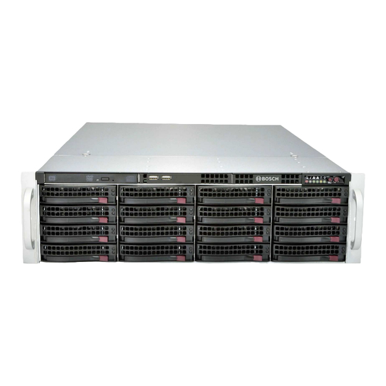
- Page 1 DIVAR IP 6000 (3U) DIP-61F0-00N | DIP-61F3-16HD | DIP-61F4-16HD | DIP-61F6-16HD | DIP-61F8-16HD Installation Manual...
-
Page 3: Table Of Contents
Introduction Setup instruction Setting the IP address Standard system configuration RAID setup RAID setup using Remote Desktop Connection RAID setup using RAID BIOS Recovering the unit Additional software and documentation Bosch Sicherheitssysteme GmbH Installation Manual 2016.08 | V2.1 | DOC... - Page 4 Installing expansion cards 10.11 Installing the air shroud 10.12 Replacing a system fan 10.13 Replacing the power supply 10.14 Monitoring the system 10.15 Installing Video Recording Manager locally 10.16 Service and repair 2016.08 | V2.1 | DOC Installation Manual Bosch Sicherheitssysteme GmbH...
-
Page 5: Safety Information
The Low Voltage power supply unit must comply with EN/UL 60950. The power supply must be a SELV-LPS unit or a SELV - Class 2 unit (Safety Extra Low Voltage - Limited Power Source). Bosch Sicherheitssysteme GmbH Installation Manual 2016.08 | V2.1 | DOC... -
Page 6: Important Safety Instructions
Read, follow, and retain for future reference all of the following safety instructions. Follow all warnings before operating the device. – Clean only with a dry cloth. Do not use liquid cleaners or aerosol cleaners. 2016.08 | V2.1 | DOC Installation Manual Bosch Sicherheitssysteme GmbH... - Page 7 – For protection of the device, the branch circuit protection must be secured with a maximum fuse rating of 16 A. This must be in accordance with NEC800 (CEC Section 60). Bosch Sicherheitssysteme GmbH Installation Manual 2016.08 | V2.1 | DOC...
-
Page 8: Electrical Safety Precautions
SELV circuits. – If safe operation of the unit cannot be ensured, remove it from service and secure it to prevent unauthorized operation. In such cases, have the unit checked by Bosch Security Systems. –... -
Page 9: Esd Precautions
Notices Notice! This is a class A product. In a domestic environment this product may cause radio interference, in which case the user may be required to take adequate measures. Bosch Sicherheitssysteme GmbH Installation Manual 2016.08 | V2.1 | DOC... -
Page 10: Fcc And Ices Compliance
DIVAR IP 6000 (3U) Notice! Video loss is inherent to digital video recording; therefore, Bosch Security Systems cannot be held liable for any damage that results from missing video information. To minimize the risk of losing information, we recommend multiple, redundant recording systems, and a procedure to back up all analog and digital information. - Page 11 Operation of this equipment in a residential area is likely to cause harmful interference, in which case you will be required to correct the interference at your own expense. Bosch Sicherheitssysteme GmbH Installation Manual 2016.08 | V2.1 | DOC...
-
Page 12: About This Manual
This manual is written for professional system integrators and PC technicians. It provides information for the installation and use of the chassis. Installation and maintenance should be performed by experienced and qualified technicians only. 2016.08 | V2.1 | DOC Installation Manual Bosch Sicherheitssysteme GmbH... -
Page 13: System Overview
. Always use the air shroud included with your chassis. 3.2.5 Mounting rails The unit can be placed in a rack for secure storage and use. To set up your rack, follow the step-by-step instructions included in this manual. Bosch Sicherheitssysteme GmbH Installation Manual 2016.08 | V2.1 | DOC... -
Page 14: System Interface
HDD (drive activity) Power Reset Power on/off Drive carrier LEDs (green: access to this drive/red: drive failure) Rear view: 2x power supply modules 2x redundant SSD drives for operating system (RAID1 mirror) 2016.08 | V2.1 | DOC Installation Manual Bosch Sicherheitssysteme GmbH... -
Page 15: Control Panel Buttons
Blinking blue (300 msec) Remote UID has been activated. Use this function to locate the unit from a remote location. – Overheat/fan fail: A flashing LED indicates a fan failure. Bosch Sicherheitssysteme GmbH Installation Manual 2016.08 | V2.1 | DOC... -
Page 16: Drive Carrier Leds
Solid Green: When illuminated, indicates that the power supply is on. – Solid Amber: When illuminated, indicates the power supply is plugged in and turned off, or the system is off but in an abnormal state. 2016.08 | V2.1 | DOC Installation Manual Bosch Sicherheitssysteme GmbH... - Page 17 Blinking Amber: When blinking, the system power supply temperature has reached 63”C. The system will automatically turn off when the power supply temperature reaches 70”C and restart when the power supply temperature goes below 60”C. Bosch Sicherheitssysteme GmbH Installation Manual 2016.08 | V2.1 | DOC...
-
Page 18: Rack Installation
If the chassis itself shows damage, file a damage claim with the carrier who delivered it and notify the respective Bosch RMA desk. Due to the weight of the system: After opening the top of the shipping box, one person should stand at either end and lift the disk array out together. -
Page 19: General System Precautions
Also refer to the installation instructions that came with the rack unit you are using. Notice! This rail will fit a rack between 26.5" and 36.4" deep. Bosch Sicherheitssysteme GmbH Installation Manual 2016.08 | V2.1 | DOC... -
Page 20: Identifying The Sections Of The Rack Rails
To separate the inner and outer rails: Locate the rail assembly in the chassis packaging. Extend the rail assembly by pulling it outward. Press the quick-release tab. 2016.08 | V2.1 | DOC Installation Manual Bosch Sicherheitssysteme GmbH... -
Page 21: Installing The Inner Rails On The Chassis
The following picture shows the inner rails installed on the chassis. 4.3.4 Installing the outer rails to the rack Outer rails attach to the rack and hold the chassis in place. Bosch Sicherheitssysteme GmbH Installation Manual 2016.08 | V2.1 | DOC... -
Page 22: Installing The Chassis In The Rack
Mounting the chassis into the rack requires at least two people to support the chassis during installation. Please follow safety recommendations printed on the rails. Notice! Figures are for illustrative purposes only. Always install chassis into racks from the bottom 2016.08 | V2.1 | DOC Installation Manual Bosch Sicherheitssysteme GmbH... -
Page 23: Installing The Chassis In A Telco Rack
(four in total). First, determine how far the chassis will extend out the front of the rack. Larger chassis should be positioned to balance the weight between front and back. If a Bosch Sicherheitssysteme GmbH Installation Manual 2016.08 | V2.1 | DOC... -
Page 24: Turning On The System
Plug the power cord from the power supply unit into a high-quality power strip that offers protection from electrical noise and power surges. We recommended using an uninterruptible power supply (UPS). Press the power button on the control panel to turn on the system. 2016.08 | V2.1 | DOC Installation Manual Bosch Sicherheitssysteme GmbH... -
Page 25: System Setup - First Steps
Open the Microsoft Utility Server Manager and follow the instructions on the screen to configure the network interface cards (NICs). IP Helper tool The IP Helper tool is available for download as follows: Bosch Sicherheitssysteme GmbH Installation Manual 2016.08 | V2.1 | DOC... -
Page 26: Standard System Configuration
The system comes with iSCSI Target Service enabled. Notice! On empty systems you must set up the iSCSI target and the iSCSI LUNs of the drives manually after initial RAID configuration. 2016.08 | V2.1 | DOC Installation Manual Bosch Sicherheitssysteme GmbH... -
Page 27: Raid Setup
18. Finish the wizard and exit the Server Manager program. Notice! Before you can store video recordings on the drive, you must perform a basic setup using the video software configuration tool, for example, Configuration Manager or Bosch VMS Configuration Client. Bosch Sicherheitssysteme GmbH Installation Manual 2016.08 | V2.1 | DOC... -
Page 28: Raid Setup Using Raid Bios
Select all hard drives that are part of the RAID group. Start the virtual drive initialization. Exit the MegaRAID Configuration Utility program. Perform a complete system recovery (Initial Factory Setup). See also – Recovering the unit, page 29 2016.08 | V2.1 | DOC Installation Manual Bosch Sicherheitssysteme GmbH... -
Page 29: Recovering The Unit
After the restart of the unit, the factory default settings are installed and the Windows logon screen is displayed. The factory default settings are: – IP address: DHCP (Fallback: 192.168.0.200) – Subnet mask: 255.255.255.0 – User: BVRAdmin – Password: WSS4Bosch Bosch Sicherheitssysteme GmbH Installation Manual 2016.08 | V2.1 | DOC... -
Page 30: Additional Software And Documentation
Software for configuration of hardware and software is available on the online product catalogue. Documentation and software for Bosch Security Systems products can be found in the online product catalogue as follows: Open any browser > enter www.boschsecurity.com > select your region and your country >... -
Page 31: Oss Licenses
This chapter provides an overview on used Open Source Licenses in DIVAR IP 6000. The license packages are either used completely or only some parts within a package are used. MIT - iniparser Bosch Sicherheitssysteme GmbH Installation Manual 2016.08 | V2.1 | DOC... -
Page 32: Ms-Pl - Msdn Library
| OSS licenses DIVAR IP 6000 (3U) MS-PL - MSDN Library 2016.08 | V2.1 | DOC Installation Manual Bosch Sicherheitssysteme GmbH... -
Page 33: Ntp License - Ntp Project
DIVAR IP 6000 (3U) OSS licenses | en NTP License - NTP Project Bosch Sicherheitssysteme GmbH Installation Manual 2016.08 | V2.1 | DOC... -
Page 34: Maintenance
Although not frequently, you may need replacement parts for your system. To ensure the highest level of professional service and technical support, you must register the systems according to the instructions available as part of the shipment as well as online from the Bosch product catalog. 10.2 Removing power from the system Before performing some setup or maintenance tasks, use the following procedure to ensure that power has been removed from the system. -
Page 35: Removing The Chassis Cover
The hard drives are mounted in hard drive carriers to simplify their installation and removal from the chassis. These hard drive carriers also help promote proper airflow for the hard drive bays. Bosch Sicherheitssysteme GmbH Installation Manual 2016.08 | V2.1 | DOC... -
Page 36: Installing A Hard Drive Into A Hard Drive Carrier
The hard drives are mounted in hard drive carriers. To install a hard drive into a hard drive carrier: Remove the screws securing the dummy drive to the hard drive carrier. 2016.08 | V2.1 | DOC Installation Manual Bosch Sicherheitssysteme GmbH... - Page 37 Notice! We recommend using the respective Bosch hard disk drives. The hard disk drives as one of the critical component are carefully selected by Bosch based on available failure rates. HDD – not delivered from Bosch – are not supported. Information on supported HDDs can be found in the datasheet in the Bosch Online Product Catalog.
-
Page 38: Installing A Hard Drive Into A Front Drive Bay
The hard drives are mounted in hard drive carriers to simplify their installation and removal from the chassis. These hard drive carriers also help promote proper airflow for the hard drive bays. 2016.08 | V2.1 | DOC Installation Manual Bosch Sicherheitssysteme GmbH... -
Page 39: Installing A Hard Drive Into A Rear Hard Drive Carrier
Notice! We recommend using the respective Bosch hard disk drives. The hard disk drives as one of the critical component are carefully selected by Bosch based on available failure rates. HDD – not delivered from Bosch – are not supported. Information on supported HDDs can be found in the datasheet in the Bosch Online Product Catalog. -
Page 40: Installing A Hard Drive Into A Rear Drive Bay
Replace the chassis cover. replace the unit in the rack, if necessary, then turn on the system. 10.8 Replacing the front port panel If you must install a new or replace a damaged front port panel, observe the following instructions. 2016.08 | V2.1 | DOC Installation Manual Bosch Sicherheitssysteme GmbH... -
Page 41: Installing The Motherboard
Secure the expansion card shield to the chassis using the screw previously removed. 10.11 Installing the air shroud The air shroud does not require screws for its installation. Bosch Sicherheitssysteme GmbH Installation Manual 2016.08 | V2.1 | DOC... -
Page 42: Replacing A System Fan
The fans might still be turning when you remove the fan assembly from the chassis. Keep fingers, screwdrivers, and other objects away from the openings in the fan assembly's housing. 2016.08 | V2.1 | DOC Installation Manual Bosch Sicherheitssysteme GmbH... -
Page 43: Replacing The Power Supply
Replacing the power supply The chassis has a redundant power supply. Redundant power supplies are hot-swappable, and can be changed without turning off the system. Replacement units can be ordered directly from Bosch RMA desk. Warning! Redundant power supplies This unit might have more than one power supply connection. To de-energize the unit, remove all connections. -
Page 44: Monitoring The System
Double-click the SuperDoctor 5 service icon on the screen. Log on to the web interface using the following default credentials: User Name: ADMIN Password: ADMIN Click the Configuration tab, then click Password Settings and change the default password. 2016.08 | V2.1 | DOC Installation Manual Bosch Sicherheitssysteme GmbH... -
Page 45: Installing Video Recording Manager Locally
The storage equipment is shipped with an original manufacturer Service and Support agreement. Bosch RMA Desk is the Single Point of Contact in case of failure but the Service and Support obligations are fulfilled by the manufacturer or a partner. - Page 46 | Maintenance DIVAR IP 6000 (3U) Opening Hours: Monday to Friday, 08:30 – 17:30 – RMA Contact EMEA Bosch Security Systems, C/o EVI Audio GmbH, Ernst-Heinkel Str. 4, 94315 Straubing, GERMANY Contact person: RA Desk Supervisor Phone: +49(9421)706-366 Fax: n.a.
- Page 48 Bosch Sicherheitssysteme GmbH Robert-Bosch-Ring 5 85630 Grasbrunn Germany www.boschsecurity.com © Bosch Sicherheitssysteme GmbH, 2016...