Table of Contents
Advertisement
Quick Links
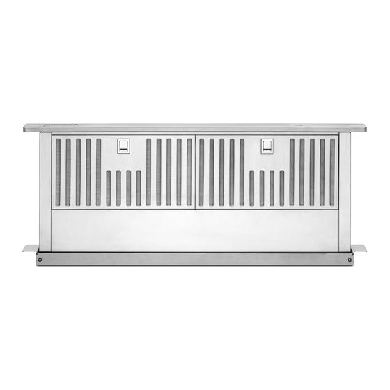
30" (76.2 CM) AND 36" (91.4 CM)
RETRACTABLE (POP-UP) DOWNDRAFT
VENT SYSTEM
Installation Instructions and Use & Care Guide
For questions about features, operation/performance, parts, accessories, or service in the U.S.A., call: 1-800-422-1230
or visit our website at www.kitchenaid.com.
In Canada, call: 1-800-807-6777, or visit our website at www.kitchenaid.ca.
SYSTÈME DE VENTILATION RÉTRACTABLE
(CLAPET) DE 30" (76,2 CM) ET 36" (91,4 CM) –
ASPIRATION PAR LE BAS
Instructions d'installation et Guide d'utilisation et d'entretien
Pour des questions à propos des caractéristiques, du fonctionnement/rendement, des pièces, accessoires ou dépannage, composer le :
1-800-422-1230 ou visitez notre site web à www.kitchenaid.com.
Au Canada, composer le : 1-800-807-6777 ou visitez notre site web à www.kitchenaid.ca.
IMPORTANT: READ AND SAVE THESE INSTRUCTIONS.
FOR RESIDENTIAL USE ONLY.
IMPORTANT : LIRE ET CONSERVER CES INSTRUCTIONS.
POUR UTILISATION RÉSIDENTIELLE UNIQUEMENT.
LI3ZTC/W10342489G
Advertisement
Table of Contents

Related Manuals for KitchenAid KXD4630YSS0


Summary of Contents for KitchenAid KXD4630YSS0
- Page 1 Pour des questions à propos des caractéristiques, du fonctionnement/rendement, des pièces, accessoires ou dépannage, composer le : 1-800-422-1230 ou visitez notre site web à www.kitchenaid.com. Au Canada, composer le : 1-800-807-6777 ou visitez notre site web à www.kitchenaid.ca. IMPORTANT: READ AND SAVE THESE INSTRUCTIONS.
-
Page 2: Table Of Contents
TABLE OF CONTENTS TABLE DES MATIÈRES VENT SYSTEM SAFETY..............3 SÉCURITÉ DU SYSTÈME DE VENTILATION ......30 INSTALLATION REQUIREMENTS ..........5 EXIGENCES D'INSTALLATION ...........32 Tools and Parts ................5 Outils et pièces ................32 Location Requirements ..............5 Exigences d’emplacement ............32 Electrical Requirements ...............8 Spécifications électriques ............36 Venting Requirements ..............8 Exigences concernant l'évacuation ...........36 INSTALLATION INSTRUCTIONS... -
Page 3: Vent System Safety
VENT SYSTEM SAFETY Your safety and the safety of others are very important. We have provided many important safety messages in this manual and on your appliance. Always read and obey all safety messages. This is the safety alert symbol. This symbol alerts you to potential hazards that can kill or hurt you and others. - Page 4 IMPORTANT SAFETY INSTRUCTIONS READ AND SAVE THESE INSTRUCTIONS...
-
Page 5: Installation Requirements
INSTALLATION REQUIREMENTS Tools and Parts Location Requirements Gather the required tools and parts before starting installation. NOTE: Downdraft vent is installed directly behind the cooktop. Read and follow the instructions provided with any tools Install the downdraft vent first, and then install the cooktop. listed here. - Page 6 Product Dimensions Models with interior-mounted blower motor Models with exterior-mounted blower motor Top trim widths: 30" (76.2 cm) 4³⁄₄" (12.1 cm) 36" (91.4 cm) 13¹⁄₂" (34.3 cm) retractable vent height 13¹⁄₈" (33.4 cm) 1¹⁄₂" (3.8 cm) 6⁹⁄₁₆" (16.7 cm) ³⁄₈" (0.95 cm) 27"...
- Page 7 Cabinet Dimension Interior-mounted blower motor model Exterior-mounted blower motor model 10" (25.4 cm) ¹⁄₂" (12.7 mm) minimum A = ¹⁄₂" (12.7 mm) minimum 21⁵⁄₁₆" (54.1 cm) 21⁵⁄₁₆" (54.1 cm) Cutouts are for 3¹⁄₄" x 10" (8.3 cm x 25.4 cm) Locate power rectangular or 6"...
-
Page 8: Electrical Requirements
Venting Requirements IMPORTANT: Make sure there is proper clearance within the wall or floor before making exhaust vent cutouts. Use heavy (rigid) metal vent. ■ Venting system must terminate to the outside. ■ Do not terminate the vent system in an attic or other ■... -
Page 9: Installation Instructions Interior-Mounted Vent Motor
INSTALLATION INSTRUCTIONS INTERIOR-MOUNTED VENT MOTOR Venting Methods Island Location – Vent System Installed Under Determine which venting method is best for your application. Vent system can terminate either through the wall or floor. a Concrete Slab Using PVC Sewer Pipe Front- (Standard) Mounted Blower Motor Island Location Front-Mounted (Standard) -
Page 10: Install Vent System
To calculate the length of the system you need, add the Example Vent System equivalent feet (meters) for each vent piece used in the system. 6 ft " x 10" (8.3 cm x 25.4 cm) (1.8 m) Vent Piece Rectangular "... - Page 11 5. Attach the support legs to the side of the vent box with Left or Right Venting: 4 - 4 x 8 mm screws in each support leg. Adjust to dimension 1. Using 2 or more people, place the downdraft vent system “Y”...
-
Page 12: Rear Mounting - Blower Motor
Rear Mounting – Blower Motor NOTE: Optional blower motor rear-mounting position Rear View (opposite side) for island cabinet locations. The blower motor box assembly can be moved to the opposite side (rear) of the vent box. 1. Remove 7 screws from the mounting flanges of the blower motor box. - Page 13 6. Hold the wire-mounting plate and push the grommet out 14. Remove the front cover from the deep cover, place the front of the wire-mounting plate. cover over the previously mounted cover box, and secure using the 4 screws previously removed. A.
-
Page 14: Complete Installation
2. Remove 4 screws attaching the terminal box cover. Complete Installation (Interior-Mounted Motor) NOTE: The downdraft vent system is supplied with a 3 " x 10" (8.3 cm x 25.4 cm) back draft damper and a 6" (15.2 cm) round vent transition with damper. - Page 15 5. Install the left and right undercounter mounting brackets to 7. Check that the downdraft vent is level as shown below. the vent box. Slide the keyhole slots over the guide tabs and Loosen the lower support leg screws and position the legs push the brackets up to set them in place.
-
Page 16: Make Electrical Connections
Make Electrical Connections Check Operation 1. Push and hold the button on the top of the downdraft vent WARNING for a few seconds. The retractable section of the downdraft vent will rise and the blower will be able to start using the control slider. -
Page 17: Installation Instructions Exterior-Mounted Vent Motor
INSTALLATION INSTRUCTIONS EXTERIOR-MOUNTED VENT MOTOR CAUTION: To reduce the risk of fire and electrical shock, NOTE: Exterior-mounted vent motor installations require install the downdraft only with remote blower systems an approved in-line blower motor system. Model numbers that are sold by Whirlpool Corporation. Model numbers UXI0600DYS (600 cfm) and UXI1200DYS (1200 cfm) are UXI0600DYS (600 cfm) and UXI01200DYS (1200 cfm). -
Page 18: Install Vent System
3. Slide the cover plate up and slip it over the keyhole slot Install Vent System shoulder screws. Set the cover aside. 4. Install the 10" diameter vent collar plate to the vent box where the cover plate was removed in the previous step. WARNING Secure using the 4 screws from the cover plate. - Page 19 4. Install the left and right undercounter mounting brackets to 6. Check that the downdraft vent is level as shown below. the vent box. Slide the keyhole slots over the guide tabs and Loosen the lower support legs screws and position the push the brackets up to set them in place.
-
Page 20: Install Downdraft Vent In-Line (External Type) Blower Motor
Install Downdraft Vent In-Line (External Type) Blower Motor NOTE: Your downdraft vent requires you to purchase an Install In-line Blower System in-line (external type) blower motor system. See “Blower Motor System” in the “Accessories” section. NOTE: The blower motor housing can be mounted using 4 holes from either the inlet side or the outlet side of the blower. -
Page 21: Make Electrical Connections For In-Line Blower Motor System
4. Locate the electrical terminal boxes in the in-line blower Make Electrical Connections for In-Line housing and downdraft vent. Remove the terminal box covers and set the covers and screws aside. Blower Motor System WARNING Electrical Shock Hazard Disconnect power before servicing. Replace all parts and panels before operating. -
Page 22: Make Electrical Power Supply Connection To Downdraft Vent
7. Use UL listed wire connectors and connect the gray wires Make Electrical Power Supply Connection (G) together. to Downdraft Vent WARNING WARNING Electrical Shock Hazard Electrically ground blower. Electrical Shock Hazard Connect ground wire to green and yellow ground wire Disconnect power before servicing. -
Page 23: Check Operation
4. Use UL listed wire connectors and connect white wires Check Operation (B) together. WARNING 1. Push and hold the button on the top of the downdraft vent for a few seconds. The retractable section of the downdraft vent will rise and the blower will be able to start using the control slider. -
Page 24: Vent System Use
VENT SYSTEM USE The retractable downdraft vent system is designed to remove Operating Downdraft Vent smoke, cooking vapors, and odors from the cooktop area. For best results, the vent should be operating before cooking To Use: ■ is started. 1. Push and hold the button on top of downdraft vent for a few If you use large or tall utensils, place them on the large rear seconds. -
Page 25: Troubleshooting
In Canada, visit http://www.kitchenaid.ca. Contact us by mail with any questions or concerns at the address below: In Canada: In the U.S.A.:... -
Page 26: Wiring Diagrams
WIRING DIAGRAMS Interior-Mounted Blower Motor Motor Resistance Motor Specifications YL/GN Power supply Blue - White 120 VAC 21.6 Ohms 18 Ohms Frequency Blue - Red 60 Hz Blue - Gray 14.3 Ohms Wattage rating 420 W Blue - Black 9.8 Ohms Amperage 3.7 A Blower Switch operation... -
Page 27: Exterior-Mounted Blower Motor
Exterior-Mounted Blower Motor SEL0016521A Note: Wiring for external blower motor Component Layout Num. Description Filter microswitch Filter microswitch Plenum Down Limit Switch Plenum Up Limit Switch Motor Specifications Motor microswitch Power supply Plenum Drive Motor 120VAC Blower Motor Frequency 60Hz Blower Speed Switches Wattage rating 420W... -
Page 28: Assistance Or Service
■ Accessory and repair parts sales. ■ Call Whirlpool Customer eXperience Center toll-free: 1-800-422-1230 or visit our website at www.kitchenaid.com. For further assistance Our consultants provide assistance with: If you need further assistance, you can write to Whirlpool Scheduling of service. Whirlpool designated service Canada LP with any questions or concerns at: ■... -
Page 29: Warranty
DISCLAIMER OF REPRESENTATIONS OUTSIDE OF WARRANTY KitchenAid makes no representations about the quality, durability, or need for service or repair of this major appliance other than the representations contained in this warranty. If you want a longer or more comprehensive warranty than the limited warranty that comes with this major appliance, you should ask KitchenAid or your retailer about buying an extended warranty. - Page 30 ® /™ ©2016 KitchenAid. Used under license in Canada. All rights reserved. W10342489G Utilisé sous licence au Canada. Tous droits réservés. 11/16...