Table of Contents
Advertisement
Advertisement
Table of Contents
Troubleshooting

Summary of Contents for Yamaha PW3028A
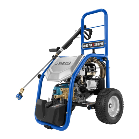
- Page 1 PRESSURE WASHER SERVICE MANUAL PW3028A PW3028B LIT-19616-PW-30 7DH-F819P-10...
-
Page 2: Table Of Contents
TABLE OF CONTENTS GENERAL INFORMATION General Check and Setup ........3 Ceramic Plunger Removal ......16 Accessory Checklist ...........4 Valve Assembly Replacement .......16 Glossary of Terms ..........4 Soap Injector Assembly Replacement ..16 Recommended Service Tools ......5 Unloader Replacement ........16 Quick Start Guide and Common Ceramic Plunger Replacement......17 Customer Errors ..........6 Plunger Chamber Replacement ....17 Manifold Replacement ........17 TROUBLESHOOTING Crankcase Seal and O-Ring Replacement ..17 ... -
Page 3: General Check And Setup
GENERAL CHECK AND SETUP Always refer to the operator’s manual delivered with the pressure washer for general checks and setup. Initial observations should be taken when the pressure washer is received at your service center. In order to create a proper record of repairs, the following should be checked before beginning service: SAFETY AND SERVICE BULLETIN CHECK: Safety All potential hazardous conditions, including but not limited to, cracked fuel lines, cracked frames and/or electrical issues, should be checked and recommended for repair if out of warranty. Out of warranty concerns should also be noted and confirmed if customer will accept the repair. Service Bulletin Any service bulletins should be checked and defects described in the service bulletin corrected. ENGINE LUBRICANT: To add or check refer to the engine manufacturer’s documentation for more information: Place pressure washer on a flat, level surface. ... -
Page 4: Accessory Checklist
ACCESSORY CHECKLIST SPRAY WAND: Determine where the leakage or failure occurs. Pressurize accessory to the rated pressure and cycle the trigger lever. If wand leaks while not activating the trigger lever, replace wand. Check O-rings and replace as needed. SPRAY WANDS/LANCES: Determine where the leakage or failure occurs. Insert nozzles and spray to rated pressure. If a new nozzle gets stuck in the coupler/fitting replace lance assembly. HIGH PRESSURE HOSE: Determine where the leakage or failure occurs. Check O-rings and connections. NOZZLES: Spray tip size is a very important factor of proper pressure washer performance. Using a tip that is sized too small will allow over pressurization of the pump and components. You must know your output GPM and your desired output PSI to properly select a spray tip size. Quick-Connect Nozzles - Spray tips are available in various spray angles/degrees; 0, 15, 25, and 40. Turbo Nozzles – These increase cleaning efficiency as much as 200% compared to a 25 degree flat fan nozzle. The 0 degree rotation creates a cleaning and tearing action. ... -
Page 5: Recommended Service Tools
RECOMMENDED SERVICE TOOLS REVERSE PLIERS HEX KEY (5 mm AND 10 mm) 100xkPa WRENCH PRESSURE (19 mm AND 24 mm) GAUGE 3/8 in. NPT MONARCH PT99 99.999 RUBBER MALLET MENU LOCK RPM METER QUICK CONNECTS NEEDLE NOSE PLIERS 0º NOZZLE SAFETY GOGGLES SEAL INSTALLATION TOOL... -
Page 6: Quick Start Guide And Common Customer Errors
QUICK START GUIDE AND COMMON CUTOMER ERRORS STARTING THE UNIT (COLD START) 1. Add fuel. Add fuel stabilizer every time you fuel the machine. 2. Turn the fuel valve to ON. 3. Put choke lever in ON (START) position. 4. Put engine switch in ON position. 5. Pull recoil starter to start. If the engine does not start after each pull of the recoil starter, squeeze the trigger to relieve water pressure before attempting to start the engine again. 6. Allow engine to run for several seconds, then move choke to OFF (RUN) position. RESTARTING THE UNIT (HOT RESTART) 1. Squeeze the trigger to relief water pressure. Unit will not start until this is done. 2. Pull recoil starter to start. If The Engine Does Not Start: * Check for enough fuel. * May need to adjust choke position. * Try starting again. DO NOT USE E15 OR E85 FUEL IN THIS UNIT. -
Page 7: General Troubleshooting
GENERAL TROUBLESHOOTING Find the section that defines the malfunction of the pump. Turn to that section's overview page and identify the specific problem. Then go to the solutions page for that specific problem. If you don't know what the problem is, work your way through the problems listed until you find and correct the problem. A. WATER SUPPLY Check faucet. 2.5 gpm is required. Outside diameter of hose should be ¾” or 5/8” Maximum length of hose should be 50’. The inlet water pressure should not exceed 90 psi. Hose should not be kinked or damaged. B. NOZZLE Check function and setting of original nozzle by using an in-house nozzle. If pump functions properly with in-house nozzle but malfunctions with original nozzle, replace nozzle. C. Water Inlet Filter Remove filter with pair of valve pliers. Clean filter. Replace filter if it is torn, bent or missing. Reinstall filter. NOTE: If water inlet filter is missing or damaged, further damage may have occurred inside the pump. D. DETERGENT INJECTOR a. Detergent not drawing Check that nozzle is in low/chemical position. Check that metering valve on pickup filter is open. Check pickup filter for clog. Check detergent tube for holes and kinks. Remove tube from nipple ... -
Page 8: Troubleshooting Chart - All Pump Types
TROUBLESHOOTING CHART - ALL PUMP TYPES SYMPTOMS CAUSES REMEDIES Detergent fails to mix with spray Detergent injection hose is not Insert injection hose into detergent properly submerged container or detergent bottle High pressure nozzle attached Use black or blue soap nozzle. Pump doesn’t produce pressure Low pressure nozzle installed Replace with high pressure nozzle Low Pressure Inadequate water supply Provide adequate water flow Trigger handle or spray wand leaks Check connections and/or replace trigger handle or spray wand Nozzle is clogged Clean nozzle Air in line Squeeze trigger on trigger handle to remove air from line Inlet filter clogged Remove filter, rinse clean and reinstall... - Page 9 TROUBLESHOOTING CHART - ALL PUMP TYPES SYMPTOMS CAUSES REMEDIES Irregular pump pressure Pump sucking air Check that there is no water leaking as it enters the pump Blocked nozzle Clean and/or replace nozzle Air in pump Pull the trigger to release air in system Water inlet filter blocked Clean filter Inadequate water supply Make sure tap is completely open and/or connect to a tap that has adequate flow rate to at least 35 PSI Worn, dirty/blocked valves Replace check valve...
-
Page 10: Diagnosis And Maintenance
DIAGNOSIS AND MAINTENANCE One of the most important steps in a high pressure system is to establish a regular maintenance program. This will vary slightly with each system and is determined by various elements such as the duty cycle, the liquid being pumped, the actual specifications vs rated specifications of the pump, the ambient conditions, the inlet conditions and the accessories in the system. A careful review of the necessary inlet conditions and protection devices required before the system is installed and eliminate many potential problems. PROBLEM PROBABLE CAUSE SOLUTION Low pressure Worn nozzle. Replace with properly sized nozzle. Air leak inlet plumbing. Tighten fittings and hoses. Use PTFE liquid or tape. Pressure gauge inoperative or not Check with new gauge. Replace worn registering accurately. or damaged gauge. Relief valve stuck, partially plugged or Clean/adjust relief valve. Replace improperly adjusted. worn/seats and o-rings. Inlet suction strainer (filter) clogged or Clean filter. Use adequate size filter. improperly sized. Check more frequently. - Page 11 DIAGNOSIS AND MAINTENANCE Oil leak Crankcase oil seals. Worn crankcase oil seals. Replace crankcase oil seals. Crankshaft oil seals Worn crankshaft oil seals or o-rings on Remove bearing cover and replace and o-rings. bearing cover. o-rings and/or oil seals. Drain plug. Loose drain plug or worn drain plug Tighten drain plug or replace o-ring. o-ring. Bubble gauge. Loose bubble gauge or worn bubble Tighten bubble gauge or replace gauge gasket. gasket. Bearing cover. Loose bearing cover or worn bearing Tighten bearing cover or replace cover o-ring.
-
Page 12: Avoid Cavitation Damage
AVOID CAVITATION DAMAGE One or several of the conditions shown in the chart below may contribute to cavitation in a system resulting in premature wear, system downtime and unnecessary operating costs. CONDITION SOLUTION Inadequate Inlet Line Hose Size Increase hose size to hose size 3/4”-5/8”. Water Hammering Liquid Hose should be no longer than 50’. Acceleration/Deacceleration Rigid Inlet Plumbing Use flexible wire reinforced hose to absorb pulsation and pressure spikes. Excessive Elbows in Inlet Plumbing Keep elbows to a minimum and less than 90°. Excessive Liquid Temperature Use Thermo Valve in bypass line. Do not exceed pump temperature 104°F. Substitute closed loop with baffled holding tank. Adequately sized tank for frequent or high volume bypass. Pressure feed high temperature liquids. Air Leaks in Plumbing Check all connections. -
Page 13: Not Warranted Examples
NOT WARRANTED EXAMPLES Oxidation damage is caused by the chemicals that purify water in city water systems. To prevent such damage, you should use Pump Protector. VALVE DEBRIS BLEACH DAMAGE Fig. 5 (GREEN OR BLUEISH COLOR) Bleach damage is caused by using it as a cleaning agent with the pressure washer. Do not use bleach as a cleaning agent. DEBRIS DAMAGE Fig. 4 Debris damage is caused when the user does not use a filter screen to filter the water that is connected to the pump. Without a filter, debris can flow freely into the pump. -
Page 14: Triplex Plunger Pumps
TRIPLEX PLUNGER PUMPS UNLOADER TYPE An integral unloader with built-in by-pass is part of the discharge manifold to provide system pressure regulation and pump protection. This pump also includes a fixed chemical injector for chemical application. OPERATION Pump should be purged of air before commencing with operation. Liquid must flow through the pump without discharge restriction to assure full system pressure is reached. Install a pressure gauge close to the manifold head of the pump to assist in setting system pressure and to periodically monitor system pressure. Setting and adjusting the unloader pressure must be done with the system turned on. Start the system with the unloader backed off to the lowest pressure setting (counterclockwise direction). Squeeze the trigger and read the pressure on the gauge at the pump. Do not read pressure at the wand or nozzle. If more pressure is desired, release the trigger, turn adjusting cap one quarter turn in a clockwise direction. Squeeze the trigger and read the pressure. Repeat this process until the desired system pressure is reached. Thread locking nut up to adjusting cap. NOTE: Pressure is not set at the factory. SERVICE: The unloader should be serviced on the same schedule as the seals in the pump. PRESSURE WASHER SYSTEM HIGH PRESSURE SPRAY WAND HOSE LANCE... -
Page 15: Servicing
SERVICING 1. Loosen manifold hex socket head screws. See 5. Separate valve assembly by inserting screwdriver figure 13, page 19. into spring retainer and press the backside of valve until seat separates from the spring retainer. 2. Loosen valves caps. 6. Remove o-ring (B and K) from each seat and valve 3. Loose unloader valve and remove unloader valve. plug. See figure 15, page 20. 4. Loosen soap injector assembly (U). See figure 15, SOAP INJECTOR ASSEMBLY REMOVAL page 20. 1. Remove soap injector assembly (U). See figure 15, page 20. -
Page 16: Ceramic Plunger Removal
SERVICING CERAMIC PLUNGER REMOVAL 11. Lubricate with silicon grease and install new O-ring (B) onto each valve plug (A). 1. Remove seal retainer (B) from each plunger rod. 12. Apply thin coat Loctite 242 to threads of each See figure 10 page 19. valve plug (A) and thread in hand tight. Torque to 2. Using a 10 mm hex tool, loosen the plunger specs per chart. retainer bolt (E) on each plunger rod. SOAP INJECTOR ASSEMBLY 3. Remove the ceramic plunger (C) and washer (D) from each chamber. Depending on the model REPLACEMENT... -
Page 17: Ceramic Plunger Replacement
SERVICING 9. Examine spring retainer (D) and pressure spring 6. Lubricate and install o-ring (C) on each seal case (C) for fatigue or breaks and replace as needed. (B). Press small end of seal case (B) into each manifold chamber. 10. Place spring retainer (D) into piston retainer (E), followed by pressure spring (C) after greasing it. 7. Press new low pressure seal (A) into each seal case with the spring towards seal case. 11. Thread brass adjusting cap (A) onto piston retainer (E) by turning in a clockwise direction. MANIFOLD REPLACEMENT CERAMIC PLUNGER REPLACEMENT 1. Rotate crankshaft by hand so the two outside plungers are extended equally. - Page 18 SERVICING VALVE ASSEMBLY VALVE PLUG (A) LOW PRESSURE SEAL O- RING (B) SEAL CASE VALVE (C) O-RING SPRING (D) HIGH PRESSURE SEAL SEAT SPRING RETAINER (E) MALE ADAPTER MANIFOLD SEAL CHAMBER O-RING SEAL VALVE SEAT SPRING Fig. 9 REVERSE PLIERS SPRING RETAINER O-RING Fig. 8...
- Page 19 SERVICING CAT PUMP TORQUE SETTINGS CRANKCASE Pump Item Torque (in lbs.) Plunger Retainer CERAMIC Manifold Head Screws PLUNGER Valve Plugs Bearing Cover Screws Bubble Oil Gauge Fig. 12 SEAL CERAMIC PLUNGER SEAL RETAINER CRANKCASE WASHER PLUNGER RETAINER BOLT Fig. 10 TORQUE SEQUENCE MANIFOLD Fig. 13 Fig. 11 BEARING COVER SEAL BOLT O-RING Fig. 14...
- Page 20 INTEGRAL UNLOADER SPECIFICATIONS U.S. Measure Metric Measure Flow ......................3.0 GPM ....(11.36 L/M) PSI Range ................... 100-3000 PSI .... (7-206.8 BAR) Inlet Port....................3/4 in. GHF ....(3/4 in. GHF) Discharge Port ..................M18 x 1.0 ....(M18 x 1.0) LOCK NUT PRESSURE SPRING UNLOADER SPRING ASSEMBLY RETAINER PISTON RETAINER O-RING BACK-UP SOAP RING INJECTOR KIT O-RING PISTON STEM WASHER...
-
Page 21: Idle Down Adjustment
SERVICING IDLE DOWN ADJUSTMENT See Figures 16-17. CABLE ADJUSTMENT 1. Set the outer cable (A) about 16 to 17 rings out. BOLT See figure 16. OUTER CABLE 2. Set the engine idle adjustment (C) idle setting to 2800 RPM. See figure 17. NO LOAD 2200-2800 RPM OUTLET 2550 PSI Minimum LOADED 3350-3500 RPM BYPASS 4400 PSI Max 2.7 GPM Minimum IDLE DOWN 2200-2800 RPM Fig. 16 ENGINE IDLE ADJUSTMENT Fig. 17... -
Page 22: Cat Pump Repair Kits
CAT PUMP REPAIR KITS CAT PUMP REPAIR KITS (FOR MODEL 4GXT31) SEAL KIT (Part Number 7DH-R4100-00) Fig. 18 VALVE KIT (Part Number 7DH-R4101-00) Fig. 20 O-RING KIT (Part Number 7DH-R4102-00) Fig. 19 CHECK VALVE KIT (Part Number 7DH-R4104-00) Fig. 21... - Page 23 CAT PUMP REPAIR KITS (Continued) INJECTOR (Part Number 7DH-R4138-01) Fig. 22 BUBBLE OIL GAUGE WITH GASKET (Part Number 7DH-R4137-00) Fig. 24 OIL DRAIN PLUG CHEMICAL INJECTOR KIT (Part Number 7DH-R413A-00) (Part Number 7DH-R4105-00) Fig. 23 Fig. 25...
-
Page 24: Pump Replacement
PUMP REPLACEMENT TRIPLEX PLUNGER PUMPS I nstallation: Removal: Before installing the pump, it is best to apply a copper based antiseize compound to the engine shaft. This There are instances where replacing the pump may be allows easier removal of the pump from the engine in less repair hours than trying to determine what is the the future. problem. Follow these basic steps to remove any 4-bolt style, direct-drive pump. Hold rectangular shaft key in place on the engine shaft keyway. Remove four bolts and lock washers holding pump to engine. Not all pumps use lock washers. Keep ... -
Page 25: Pump Pressure Setting Procedure
PUMP PRESSURE SETTING PROCEDURE PRESSURE SETTING PROCEDURE See Figures 26-28. Attach a (A) high pressure gage that has a (B) male and (C) female 3/8 quick disconnect on it to the outlet of the pump. The gage must be rated to over 5000 PSI and have a discrimination of not more than 100 PSI. See Figure 26. Install a (A) red zero degree nozzle to the (C) wand extension. The zero degree nozzle is 100xkPa normally the least used and therefore should have less wear. If the zero degree nozzle is missing, any of the other high pressure nozzles may be used but the outlet pressure may be a slightly lower due to normal wear of the nozzle. -
Page 26: Cat Pump High Pressure Setting Procedure
CAT PUMP HIGH PRESSURE SETTING PROCEDURE Hold the unloader (A) with a 7/8 in. wrench (B), turn the locking nut (C) down to the unloader and tighten the locking nut using torque setting as shown. Mark the nut and cap with a paint dot to indicate if the customer has adjusted the unloader at a later time. (See Figure 29.) If the pump has heat damage, due to running pump with no water in it then this would not covered under warranty. If the pump has no pressure after the above adjustment, further analysis is required. 50 in. lbs. 50 in. lbs. FILLER PLUG 750 in. lbs. BEARING COVER SCREWS 50 in. lbs. MANIFOLD HEAD SCREWS 132 in. -
Page 27: General Specifications
GENERAL SPECIFICATIONS RESISTANCE OF VALVES AND FITTINGS Equivalent Length of Standard Pipe in Feet Nominal Inside Pipe Size Diameter Gate Globe Angle 180º Tee Thru Tee Thru Inches Inches Valve Valve Valve 45º Elbow 90º Elbow Elbow Branch 0.622 0.41 18.5 0.78 1.67... - Page 28 GENERAL SPECIFICATIONS WATER LINE PRESSURE LOSS PRESSURE DROP IN PSI PER 100 FEET Water Steel Pipe - Nominal Dia. Brass Pipe - Nominal Dia. Copper Tubing O.D. Type L 1¼ 1½ 1¼ 1½...