Table of Contents
Advertisement
Quick Links
Advertisement
Table of Contents

Related Manuals for Makita DTW701RTJ


Summary of Contents for Makita DTW701RTJ
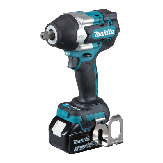
- Page 1 INSTRUCTION MANUAL Cordless Impact Wrench DTW700 DTW701 Read before use.
-
Page 2: Specifications
SPECIFICATIONS Model: DTW700 DTW701 Fastening capacities Standard bolt M10 - M24 High tensile bolt M10 - M16 Square drive 12.7 mm No load speed Max impact mode (4) 0 - 2,200 min Hard impact mode (3) 0 - 1,900 min Medium impact mode (2) 0 - 1,200 min Soft impact mode (1) -
Page 3: Ec Declaration Of Conformity
Save all warnings and instruc- WARNING: Wear ear protection. tions for future reference. WARNING: The noise emission during actual The term "power tool" in the warnings refers to your use of the power tool can differ from the declared val- mains-operated (corded) power tool or battery-operated ue(s) depending on the ways in which the tool is used (cordless) power tool. - Page 4 Remove any adjusting key or wrench before Maintain power tools and accessories. Check for turning the power tool on. A wrench or a key left misalignment or binding of moving parts, breakage of parts and any other condition that may affect the attached to a rotating part of the power tool may power tool’s operation. If damaged, have the power result in personal injury.
- Page 5 It may CAUTION: Only use genuine Makita batteries. result in a risk of overheating, possible burns Use of non-genuine Makita batteries, or batteries that and even an explosion. have been altered, may result in the battery bursting If electrolyte gets into your eyes, rinse them out causing fires, personal injury and damage. It will...
-
Page 6: Functional Description
Overheat protection FUNCTIONAL DESCRIPTION This protection works when the tool or battery is over- heated. In this situation, let the tool and battery cool CAUTION: Always be sure that the tool is before turning the tool on again. switched off and the battery cartridge is removed Overdischarge protection before adjusting or checking function on the tool. This protection works when the remaining battery Installing or removing battery cartridge capacity gets low. In this situation, remove the battery from the tool and charge the battery. - Page 7 Switch action ► 1 . Button To turn on the lamp status, press the button for one second. To ► 1 . Switch trigger turn off the lamp status, press the button for one second again. With the lamp status ON, pull the switch trigger to turn on CAUTION: Before installing the battery car- the lamp. To turn off, release it. The lamp goes out approxi-...
-
Page 8: Changing The Application Mode
This tool has a reversing switch to change the direction of rotation. When the reversing switch lever is in the neutral posi- Depress the reversing switch lever from the A side for clockwise tion, the switch trigger cannot be pulled. rotation or from the B side for counterclockwise rotation. - Page 9 Changing the application mode This tool employs several easy-to-use application modes for driving bolts with good control. The type of the application mode changes every time you press the button You can change the application mode within approximately one minute after releasing the switch trigger. NOTE: You can extend the time to change the application mode approximately one minute if you press the but- Application mode Feature Purpose (Assist type displayed on panel) Bolt mode Clockwise Clockwise This mode helps to repeat screw- Preventing over tightening of driving continuously with equal bolts. torque. This mode also helps to Counterclockwise reduce the risk of breakage of Loosening bolts.
- Page 10 Application mode Feature Purpose (Assist type displayed on panel) Bolt mode (3) Clockwise – The tool stops automatically approximately 1 second later from the moment that the tool has started impact blows. Counterclockwise The tool slows down the rota- tion after it has stopped impact blows. : The lamp is on.
-
Page 11: Installing Hook
For impact socket with O-ring and pin For tool with firm fit detent pin Optional accessory ► 1 . Impact socket 2. O-ring 3. Pin ► 1 . Impact socket 2. Hole 3. Square drive 4. Detent Move the O-ring out of the groove in the impact socket and remove the pin from the impact socket. -
Page 12: Operation
Proper fastening torque for high tensile bolt with OPERATION max impact mode (4) • CAUTION: Always insert the battery cartridge (kgf•cm) all the way until it locks in place. If you can see the red indicator on the upper side of the button, it is not locked completely. Insert it fully until the red indicator (3060) cannot be seen. If not, it may accidentally fall out of... -
Page 13: Maintenance
To maintain product SAFETY and RELIABILITY, repairs, any other maintenance or adjustment should be performed by Makita Authorized or Factory Service Centers, always using Makita replacement parts. OPTIONAL ACCESSORIES CAUTION: These accessories or attachments are recommended for use with your Makita tool specified in this manual. The use of any other accessories or attachments might present a risk of injury to persons. Only use accessory or attachment for its stated purpose. If you need any assistance for more details regard- ing these accessories, ask your local Makita Service Center. - Page 16 Makita Europe N.V. Jan-Baptist Vinkstraat 2, 3070 Kortenberg, Belgium Makita Corporation 3-11-8, Sumiyoshi-cho, Anjo, Aichi 446-8502 Japan 885799-222 www.makita.com 20200304...