Table of Contents
Advertisement
Quick Links
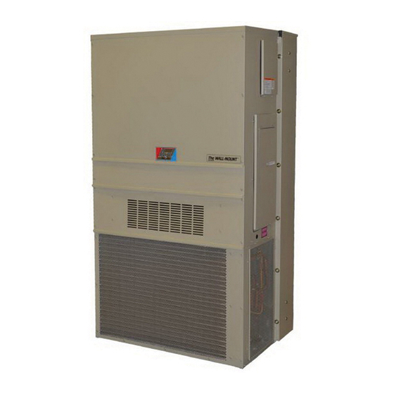
INSTALLATION INSTRUCTIONS
WALL MOUNTED
PACKAGE HEAT PUMPS
Bard Manufacturing Company, Inc.
Bryan, Ohio 43506
Since 1914...Moving ahead just as planned.
MODELS
C24H1
C30H1
C36H1
C42H1
C48H1
C60H1
Manual :
2100-586B
Supersedes:
2100-586A
File:
Volume III Tab 17
Date:
11-27-13
Manual
2100-586B
Page
1 of 25
Advertisement
Table of Contents
Troubleshooting

Related Manuals for Bard C24H1 Series


Summary of Contents for Bard C24H1 Series
- Page 1 INSTALLATION INSTRUCTIONS WALL MOUNTED PACKAGE HEAT PUMPS MODELS C24H1 C30H1 C36H1 C42H1 C48H1 C60H1 Bard Manufacturing Company, Inc. Manual : 2100-586B Supersedes: 2100-586A Bryan, Ohio 43506 File: Volume III Tab 17 Since 1914...Moving ahead just as planned. Date: 11-27-13 Manual...
-
Page 2: Table Of Contents
Contents Getting Other Information and Publications Start Up General ............... 14 Wall Mount General Information Topping Off System Charge ........14 Wall Mount Model Nomenclature ......4 Safety Practices ............14 Shipping Damage ............. 4 Important Installer Note ........... 15 General .............. -
Page 3: Getting Other Information And Publications
GETTING OTHER INFORMATION AND PUBLICATIONS FOR MORE INFORMATION, CONTACT These publications can help you install the air conditioner or heat pump. You can usually find these THESE PUBLISHERS: at your local library or purchase them directly from the publisher. Be sure to consult current edition of each ACCA Air Conditioning Contractors of America standard. -
Page 4: Wall Mount General Information
WALL MOUNT GENERAL INFORMATION HEAT PUMP WALL MOUNT MODEL NOMENCLATURE – MODEL REVISIONS CONTROL MODULES NUMBER 0C - 0KW (See Spec. Sheet S3459) 0Z - 0KW CAPACITY | 04 - 4KW 24 - 2 Ton H - Heat Pump 05 - 5KW COIL OPTIONS 30 - 2½... -
Page 5: Duct Work
CONDENSATE DRAIN Any grille that meets with 5/8 inch louver criteria may be used. It is recommended that Bard Return Air Grille Kit A plastic drain hose extends from the drain pan at RG2 through RG5 or RFG2 through RFG5 be installed the top of the unit down to the unit base. -
Page 6: Installation Instructions
INSTALLATION INSTRUCTIONS WARNING WARNING Failure to bolt the unit to the wall could result Failure to provide the 1/4 inch clearance in the unit falling, causing injury or death! between the supply duct and a combustible Follow all mounting instructions. surface for the first 3 feet of duct can result in fire causing damage, injury or death. -
Page 7: Figure 2 Unit Dimensions
FIGURE 2 Dimensions of Basic Unit for Architectural & Installation Requirements (Nominal) SUPPLY RETURN WIDTH DEPTH HEIGHT MODEL C24H1 38.200 17.125 70.563 7.88 27.88 13.88 27.88 40.00 10.88 25.75 17.93 26.75 28.75 29.25 27.00 2.63 39.13 22.75 9.14 5.00 12.00 5.00 C30H1 C36H1 42.075 22.432 84.875... -
Page 8: Figure 3A Mounting Instructions C24H, C30H
Manual 2100-586B Page 8 of 25... -
Page 9: Figure 3B Mounting Instructions C36, 42, 48, 60H
Manual 2100-586B Page 9 of 25... -
Page 10: Figure 4 Electric Heat Clearance
FIGURE 4 ELECTRIC HEAT CLEARANCE SIDE SECTION VIEW OF SUPPLY AIR DUCT FOR WALL MOUNTED UNIT SHOWING 1/4 INCH CLEARANCE TO COMBUSTIBLE SURFACES. WARNING A minimum of 1/4 inch clearance must be maintained between the supply air duct and combustible materials. This is required for the first 3 feet of ducting. -
Page 11: Figure 5 Wall Mounting Instructions
FIGURE 5 WALL MOUNTING INSTRUCTIONS WALL STRUCTURE SEE FIGURE 3 – MOUNTING INSTRUCTIONS FACTORY SUPPLIED RAIN FLASHING. MOUNT ON UNIT BEFORE INSTALLATION SUPPLY AIR SUPPLY AIR SUPPLY AIR DUCT OPENING OPENING RETURN AIR RETURN AIR RETURN AIR OPENING OPENING OPENING BOTTOM MOUNTING WOOD OR STEEL SIDING BRACKET. -
Page 12: Figure 7 Common Wall Mounting Installations
FIGURE 7 COMMON WALL MOUNTING INSTALLATIONS SUPPLY DUCT MAY BE LOCATED IN AN ATTIC OR BELOW CEILING RAFTERS AS SHOWN RAIN RAIN FLASHING RAFTERS FLASHING RAFTERS FINISHED CEILING SURFACE SUPPLY AIR DUCT SUPPLY AIR DUCT FINISHED CEILING SURFACE W/ GRILLE RETURN AIR RETURN AIR OPENING W/ GRILLE... -
Page 13: Wiring - Main Power
WIRING – LOW VOLTAGE WIRING WIRING – MAIN POWER Refer to the unit rating plate for wire sizing information 230/208V, 1 phase and 3 phase units are equipped with and maximum fuse or “HACR” type circuit breaker dual primary voltage transformers. All equipment size. -
Page 14: Start Up
8. Store cylinders in a cool area, out of direct sunlight. TOPPING OFF SYSTEM CHARGE 9. Never heat cylinders above 125°F. If a leak has occurred in the system, Bard 10. Never trap liquid R-410A in manifold sets, gauge Manufacturing recommends reclaiming, evacuating lines or cylinders. R-410A expands significantly (see criteria above), and charging to the nameplate at warmer temperatures. -
Page 15: Important Installer Note
START UP (Continued) IMPORTANT INSTALLER NOTE PHASE MONITOR For improved start up performance wash the indoor coil All units with three phase scroll compressors are with a dish washing detergent. equipped with a 3-phase line monitor to prevent compressor damage due to phase reversal. HIGH &... -
Page 16: Sequence Of Operation
SEQUENCE OF OPERATION The heat pump defrost control board has an option of 30, 60 or 90-minute setting. By default, this unit is shipped from COOLING STAGE 1 – Circuit R-Y makes at thermostat the factory with the defrost time on the 60 minute pin. If pulling in compressor contactor, starting the compressor and circumstances require a change to another time, remove the outdoor motor. -
Page 17: Figure 8 Defrost Control Board
FIGURE 8 DEFROST CONTROL BOARD TIME (SEC) LOW PRESSURE BYPASS TIMER SWITCH 120* *(FACTORY SETTING 120 SECONDS) ACCUMULATED DEFROST TIME TIMER (FACTORY SETTING 60 MIN.) MIS-2668 A Manual 2100-586B Page 17 of 25... -
Page 18: Troubleshooting
TROUBLESHOOTING SOLID STATE HEAT PUMP CONTROL NOTE: If there was no power to 24 volt transformer, TROUBLESHOOTING PROCEDURE the compressor and outdoor fan motor will 1. NOTE: A thorough understanding of the defrost not start for 5 minutes. This is because of cycle sequence is essential. -
Page 19: Checking Temperature Sensor
CHECKING TEMPERATURE SENSOR 3. Check resistance reading to chart of resistance. Use OUTSIDE UNIT CIRCUIT sensor ambient temperature. (Tolerance of part is ± 10%.) 1. Disconnect temperature sensor from board and 4. If sensor resistance reads very low, then sensor is from outdoor coil. -
Page 20: Figure 9 Fan Blade Setting
TROUBLESHOOTING FAN BLADE SETTING DIMENSIONS REMOVAL OF FAN SHROUD Shown in Figure 9 is the correct fan blade setting for 1. Disconnect all power to the unit. proper air delivery across the outdoor coil. Refer to 2. Remove the screws holding both grilles, one on Table 4 for unit specific dimension. -
Page 21: Table 5A Cooling Pressure
TABLE 5A COOLING PRESSURE TABLE COOLING AIR TEMPERATURE ENTERING OUTDOOR COIL °F RETURN AIR MODEL PRESSURE 75°F 80°F 85°F 90°F 95°F 100°F 105°F 110°F 115°F 120°F TEMPERATURE 75° DB LOW SIDE 62° WB HIGH SIDE 80° DB LOW SIDE C24H 67°... -
Page 22: Table 6 Electrical Specifications C**H
TABLE 6 Electrical Specifications — C**H Series Single Circuit Multiple Circuit Rated Field k Max. Circuit Model Volts & Minimum Circuit Field Power k Max. Field Exterior Fuse Ground Wire Power Minimum External Power Ampacity Wire Size Phase... -
Page 23: Table 7 Indoor Blower Performance
TABLE 7 C**H INDOOR BLOWER PERFORMANCE - CFM (0.00" — 0.50" H 0) Rated Cooling Cooling Model Blower Electric & Heat Pump & Heat Pump Only Heat Stage 1 Stage 2 C24H C30H C36H 1100 1100 C42H 1250... -
Page 24: Troubleshooting Ge Ecm Motors
TROUBLESHOOTING GE ECM MOTORS ™ Symptom Cause/Procedure CAUTION: • Noisy blower or cabinet • Check for loose blower housing, panels, etc. Disconnect power from unit before removing or replacing • High static creating high blower speed? connectors, or servicing motor. To avoid electric shock from - Check for air whistling through seams in the motor’s capacitors, disconnect power and wait at least 5 ducts, cabinets or panels... -
Page 25: Figure 10 Control Disassembly
TROUBLESHOOTING GE ECM MOTORS CONT’D. ™ 8b. IF REPLACING AN ECM 2.3 CONTROL WITH AN ECM 2.3 Replacing ECM Control Module CONTROL, the plastic tab and shorter through-bolts are not needed. The To replace the control module for the GE variable-speed indoor blower motor control can be oriented in two positions 180°...