Table of Contents
Advertisement
Quick Links
SERVICE MANUAL
Ver 1.0 2000. 06
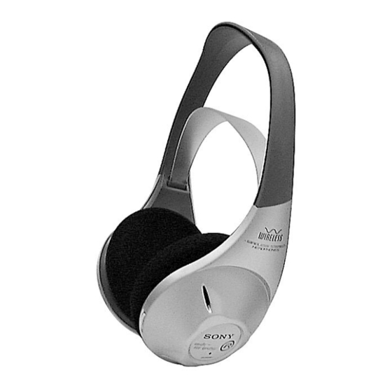
MDR-RF815R is the component model block one in the MDR-RF815RK.
COMPONENT MODEL NAME FOR MDR-RF815RK
Headphones
MDR-RF815R
Transmitter
TMR-RF815R
MDR-RF815R
SPECIFICATIONS
Headphones
Power source
DC 2.4 V: Built-in rechargeable
battery
Mass
Approx. 240 g (8.1 oz.) incl.
built-in rechargeable battery
Built-in Ni-Cd rechargeable battery
Model name
NC-AA
Voltage
1.2 V
Capacity
700 mAh
Design and specifications are subject to change without
notice.
AEP Model
UK Model
HEADPHONES
Advertisement
Table of Contents

Related Manuals for Sony MDR-RF815R


Summary of Contents for Sony MDR-RF815R
- Page 1 MDR-RF815R SERVICE MANUAL AEP Model UK Model Ver 1.0 2000. 06 MDR-RF815R is the component model block one in the MDR-RF815RK. COMPONENT MODEL NAME FOR MDR-RF815RK Headphones MDR-RF815R Transmitter TMR-RF815R SPECIFICATIONS Headphones Power source DC 2.4 V: Built-in rechargeable battery Mass Approx.
-
Page 2: Section 1 General
TUNING control until you can hear the audio signal loud and clear. B MDR-RF815R The power turns on. TUNING control VOL control... -
Page 3: Section 2 Disassembly
SECTION 2 DISASSEMBLY Note : Follow the disassembly procedure in the numerical order given. 2-1. RX-BASE BOARD × 6) 1 Four screws (P 2 Cover (R), hanger Claw 9 Switch, push (1 key) 8 Remove the two solderings. 6 RX-BASE board Claw ×... - Page 4 Set the lead wires Set the each lead wires as illustrated below. Cover (R), hanger Cover (L), hanger No.201, No.203 Groove Groove No.203 No.201 Groove No.205 Groove No.201 No.203 Groove No.204 No.202 No.202 Groove To the driver (030F032//K). To the driver (030F032//K). To the RX-BASE board No.201, No.203 Groove...
-
Page 5: Section 3 Electrical Adjustments
On adjusting the headphones section, use the transmitter as a Set the transmitter NOISE FILTER switch to OFF. jig. Input a signal of 1kHz, 316mVrms to transmitter AUDIO IN- Headphones:MDR-RF815R A-L connector only. Transmitter:TMR-RF815R Adjust the headphones tuning (RV303) to receive radio freqency. - Page 6 Adjustment Location : [RX-BASE BOARD] (Conductor side) — 6 —...
- Page 7 MDR-RF815R SECTION 4 DIAGRAMS 4-1. BLOCK DIAGRAM Note on Printed Wiring Board: • X : parts extracted from the component side. • : Through hole. • b : Pattern from the side which enables seeing. L302 Caution: IF AMP/DECODE RV302...
- Page 8 MDR-RF815R 4-2. SCHEMATIC DIAGRAM FREE RUN FREQ. 0.01 — 9 — — 10 —...
-
Page 9: Printed Wiring Board
MDR-RF815R 4-3. PRINTED WIRING BOARD • Semiconductor Location Ref. No. Location D301 D304 D310 IC301 IC302 RV303 ON/OFF SWITCH RV303 SPEAKER (L-ch) SPEAKER (R-ch) RECHARGEABLE Ni-cd NC-AA(HJ) 2pcs,2.4V — 11 — — 12 —... -
Page 10: Section 5 Exploded Views
SECTION 5 SECTION 6 RX-BASE EXPLODED VIEWS ELECTRICAL PARTS LIST NOTE: NOTE: • -XX, -X mean standardized parts, so they may • The mechanical parts with no reference number • Color Indication of Appearance Parts Example: • Due to standardization, replacements in the •... - Page 11 RX-BASE Ref. No. Part No. Description Remarks Ref. No. Part No. Description Remarks < RESISTOR > R327 1-216-085-00 METAL CHIP 1/10W R328 1-216-085-00 METAL CHIP 1/10W R302 1-216-057-00 METAL CHIP 2.2K 1/10W R330 1-216-001-00 METAL CHIP 1/10W R304 1-216-061-00 METAL CHIP 3.3K 1/10W R333...
- Page 12 MDR-RF815R Sony Corporation 2000F1646-1 Audio Entertainment Group 9-927-956-11 Printed in Japan © 2000.6 — 16 — Published by PE General Engineering Dept.
-
Page 13: Specifications
TMR-RF815R SERVICE MANUAL AEP Model UK Model Ver 1.0 2000. 06 TMR-RF815R is the component model block one in the MDR-RF815RK. COMPONENT MODEL NAME FOR MDR-RF815RK Headphones MDR-RF815R Transmitter TMR-RF815R SPECIFICATIONS General Carrier frequency 863.5 – 864.5 MHz Channel Ch1, Ch2, Ch3... - Page 14 SECTION 1 This section is extracted from instruction manual. GENERAL A To connect to a headphones jack Setting up the transmitter Transmitter to AUDIO IN A jacks Connect the transmitter to audio/video equipment. Select one of the hookups below depending on the jack type: DC IN 9V 1 2 3 OFF ON...
-
Page 15: Cabinet (Upper)
SECTION 2 DISASSEMBLY Note : Follow the disassembly procedure in the numerical order given. 2-1. CABINET (UPPER) Cabinet (upper) × 8) 1 Four screws (P 2 2-2. TX-BASE BOARD 2 TX-BASE board Cabinet assy, lower — 3 —... - Page 16 SECTION 3 ELECTRICAL ADJUSTMENTS Setting : Pilot signal Modulation Check and Adjustment 1. Set the channel to CH2. 2. No signal input (The operating time in this case is limited to 4 AF signal or 5 minutes.) generator 3. Measure the movable terminal of RV403 using an digital volt- meter (AC range) and make sure the value is 1.6mVrms ±...
- Page 17 TMR-RF815R SECTION 4 DIAGRAMS 4-1. BLOCK DIAGRAM IC403 STEREO MPX ANT401 IC401 RV403 R-CH J401 INPUT BUFFER MOD IN TIME DEVISION AUDIO IN J402 R-CH IC405(2/2) POWER OFF NOISE T-OUT BUFFER CHARGE FILTER R-CH S401 NOISE FILTER D402 VCO UNIT DIVIDER IC402 J404...
- Page 18 TMR-RF815R 4-2. SCHEMATIC DIAGRAM 330p 100k — 7 — — 8 —...
- Page 19 TMR-RF815R 4-3. PRINTED WIRING BOARD • Semiconductor Location Ref. No. Location D401 D402 D403 D404 D405 D407 D408 D410 IC401 IC402 IC403 IC404 IC405 Q401 Q402 Q404 — 9 — — 10 —...
- Page 20 SECTION 5 SECTION 6 TX-BASE EXPLODED VIEWS ELECTRICAL PARTS LIST NOTE: NOTE: • -XX, -X mean standardized parts, so they may • The mechanical parts with no reference number • Color Indication of Appearance Parts Example: • Due to standardization, replacements in the •...
-
Page 21: Metal Chip
TX-BASE Ref. No. Part No. Description Remarks Ref. No. Part No. Description Remarks L409 1-419-079-21 COIL (MPX FILTER) R463 1-216-085-00 METAL CHIP 1/10W L410 1-419-662-31 COIL, AIR-CORE R464 1-216-061-00 METAL CHIP 3.3K 1/10W L413 1-414-234-11 INDUCTOR CHIP 0uH R466 1-216-081-00 METAL CHIP 1/10W L414 1-414-234-11 INDUCTOR CHIP 0uH... - Page 22 TMR-RF815R Sony Corporation 2000F1646-1 Audio Entertainment Group 9-927-955-11 Printed in Japan © 2000.6 — 14 — Published by PE General Engineering Dept.