
Related Manuals for Kenwood TK-2140K


Summary of Contents for Kenwood TK-2140K
- Page 1 INSTRUCTION MANUAL VHF FM TRANSCEIVER TK-2140 UHF FM TRANSCEIVER TK-3140 KENWOOD CORPORATION © B62-XXXX-00 (K) 09 08 07 06 05 04 03 02 01 00...
- Page 2 THANK YOU We are grateful you chose KENWOOD for your land mobile radio applications. We believe this easy-to-use transceiver will provide dependable communications to keep personnel operating at peak efficiency. KENWOOD transceivers incorporate the latest in advanced technology. As a result, we feel strongly that you will be pleased with the quality and features of this product.
- Page 3 For information on Ni-Cd battery recycling in your area, call (toll free) 1-800-8-BATTERY (1-800-822-8837). KENWOOD’s involvement in this program is part of our commitment to preserve our environment and conserve our natural resources.
-
Page 4: Table Of Contents
CONTENTS UNPACKING AND CHECKING EQUIPMENT ....1 Supplied Accessories ........1 PREPARATION ..........2 Installing/ Removing the (Optional) Li-ion Battery Pack .. 2 Installing the (Optional) Antenna ......3 Installing the Belt Clip ........3 Installing the Cover over the Universal Connector ..4 Installing the (Optional KMC-25) Speaker/ Microphone ... - Page 5 SYSTEM SCAN (Trunking Format) ......15 Scanning Trunked Systems ......15 Scanning Conventional Systems ......15 Scan Lockout ..........16 Scan Revert ..........16 GROUP SCAN (Trunking Format) ......17 CONVENTIONAL OPERATION (Conventional Format) ..18 Transmitting ..........18 Receiving ..........18 SCAN (Conventional Format) ........ 19 Priority Scan ..........19 2-TONE SIGNALLING (Conventional Format) ....
-
Page 6: Unpacking And Checking Equipment
UNPACKING AND CHECKING EQUIPMENT Note: The following unpacking instructions are for use by your KENWOOD dealer, an authorized KENWOOD service facility, or the factory. Carefully unpack the transceiver. We recommend that you identify the items listed in the following table before discarding the packing material. -
Page 7: Preparation
PREPARATION Installing/ Removing the (Optional) Li-ion Battery Pack CAUTION: DO NOT RECHARGE THE BATTERY PACK IF IT IS ALREADY FULLY CHARGED. DOING SO MAY CAUSE THE LIFE OF THE BATTERY PACK TO SHORTEN OR THE BATTERY PACK MAY BE DAMAGED. AFTER RECHARGING THE BATTERY PACK, DISCONNECT IT FROM THE CHARGER. -
Page 8: Installing The (Optional) Antenna
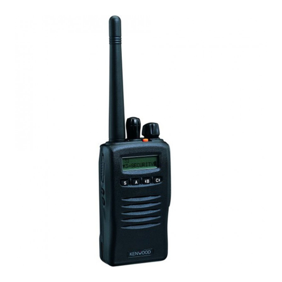
Installing the (Optional) Antenna Screw the antenna into the connector on the top of the transceiver by holding the antenna at its base and turning it clockwise until secure. Installing the Belt Clip If necessary, attach the belt clip using the two supplied 3 x 6 mm screws. -
Page 9: Installing The Cover Over The Universal Connector
Installing the Cover over the Universal Connector If you are not using the optional KMC-25 speaker/ microphone, install the cover over the univeral connector using the supplied 4 x 6 mm screw. Installing the (Optional KMC-25) Speaker/ Microphone 1 Insert the guide of the speaker/ microphone connector into the groove of the universal connector. -
Page 10: Getting Acquainted
GETTING ACQUAINTED q q q q q Antenna connector Connect an (optional) antenna here. w w w w w Rotary encoder Rotate this encoder to activate its programmable function. (System or Group Up/ Down in Trunking Format, and Group or Channel Up/ Down in Conventional Format.) For further details, contact your dealer. - Page 11 e e e e e POWER switch/ VOLUME control Turn clockwise to switch ON the transceiver. Rotate to adjust the volume. Turn counterclockwise fully to switch OFF the transceiver. r r r r r Transmit/ Battery low indicator This red LED lights during transmission. If programmed by your dealer, when the battery pack power is low, the LED flashes during transmission.
-
Page 12: Display
Display SCN LO y t i i h t e l i h t i i g i . s t s t i... -
Page 13: Programmable Auxiliary Functions
PROGRAMMABLE AUXILIARY FUNCTIONS Keys t, i and o {pages 5 and 6} can be programmed with the auxiliary functions listed in the following table. The keys can only be programmed with functions, depending on whether you are using Conventional Format or Trunking Format. Please contact your dealer for further details on these functions. - Page 14 i t c i r r i r r l a i This function can be programmed only on key t, the Auxiliary (orange) key.
-
Page 15: Operation Overview
OPERATION OVERVIEW Your dealer can program your transceiver for either Trunking Format or Conventional Format. Trunking Format This format can handle up to 32 systems with up to 250 groups in each system. The transceiver can be used in both trunked mode and conventional mode. Systems, groups, and their functions are programmed by your dealer. -
Page 16: Operating Basics
OPERATING BASICS Switching Power ON/ OFF Turn the Power switch/ Volume control clockwise to switch the transceiver ON. Turn the Power switch/ Volume control counterclockwise to switch the transceiver OFF. If the Radio Password function is programmed, “PASSWORD” will appear on the display when the power is turned ON. -
Page 17: Time-Out Timer (Tot)
Time-out Timer (TOT) The purpose of the Time-out Timer is to prevent any caller from using a channel for an extended period of time. If you continuously transmit for a period of time that exceeds the programmed time, the transceiver will stop transmitting and an alert tone will sound. -
Page 18: Trunked Operation (Trunking Format)
TRUNKED OPERATION (Trunking Format) Placing a Dispatch Call 1 Select the desired system and group using the encoder and the System or Group keys. 2 Press the PTT switch. 3 If a tone does not sound, communication is possible; start speaking into the microphone. Release the PTT switch to receive. -
Page 19: Conventional Operation (Trunking Format)
CONVENTIONAL OPERATION (Trunking Format) Transmitting 1 Select the desired system and group using the encoder and the System or Group keys. 2 Press the key programmed as Monitor to check whether or not the channel is free. • If the channel is busy, wait until it becomes free. 3 Press the PTT switch and speak into the microphone. -
Page 20: System Scan (Trunking Format)
SYSTEM SCAN (Trunking Format) If the Scan function is programmed, systems can be scanned by pressing the key programmed as Scan. When the Scan key is pressed, the SCN indicator and “-SCAN-” or the revert system/ group number, appear on the display and scanning starts. -
Page 21: Scan Lockout
Scan Lockout If a programmable auxiliary key is programmed with Scan Del/Add, each system can be locked out of the scan sequence manually. The delete indicator ( s ) will appear on the display when the selected system is locked out. Scan Revert You can select revert systems and groups using the encoder and the System or Group keys. -
Page 22: Group Scan (Trunking Format)
GROUP SCAN (Trunking Format) Group Scan is available for both trunked and conventional systems. This feature is useful when more than one group is programmed in a system. Group Scan is set by your dealer on request. It scans the revert groups as well as groups that are allowed to be scanned. -
Page 23: Conventional Operation (Conventional Format)
CONVENTIONAL OPERATION (Conventional Format) Transmitting 1 Select the desired group and channel using the encoder and the Group or Channel keys. 2 Press the key programmed as Monitor to check whether or not the channel is free. • If the channel is busy, wait until it becomes free. 3 Press the PTT switch and speak into the microphone. -
Page 24: Scan (Conventional Format)
SCAN (Conventional Format) If the Scan function is programmed, groups or channels can be scanned by pressing the key programmed as Scan. Scan can be used as either Single Scan or Multi Scan. Single Scan monitors only the channels of a single group. -
Page 25: 2-Tone Signalling (Conventional Format)
2-TONE SIGNALLING (Conventional Format) 2-Tone Signalling is either activated or deactivated by your dealer. 2-Tone Signalling only opens the squelch when the transceiver receives two tones corresponding to those set up in the transceiver. When the squelch opens, you will be able to hear the caller without any further action. After a correct 2-Tone signal is received and the squelch opens, pressing the key programmed as Monitor will cancel the connection. -
Page 26: Fleetsync™: Alphanumeric 2-Way Paging Function
FleetSync™: ALPHANUMERIC 2-WAY PAGING FUNCTION FleetSync™ is an Alphanumeric 2-way Paging Function, and is a protocol owned by KENWOOD Corporation. FleetSync™ enables a variety of paging functions on your transceiver, some of which depend on dealer programming. Key Functions i t c... -
Page 27: Selcall (Selective Calling)
Selcall (Selective Calling) A Selcall is a voice call to a particular station or to a group of stations. To Transmit: 1 Select your desired system and group (or group and channel). 2 Press the A key to enter Selcall Mode. 3 Use the encoder to select the ID of the station you want to call. -
Page 28: Status Message
• Enter an ID number (1000 ~ 4999) to make an individual call in your fleet. • Enter a Fleet number followed by an ID number to make an individual call in your desired fleet (Inter-fleet call). • Select “ALL” Fleet and “ALL” ID to make a call to all units (Broadcast call). - Page 29 To Transmit: 1 Select your desired system and group (or group and channel). 2 Press the A key to enter Selcall Mode. 3 Use the encoder to select the ID of the station you want to call. 4 Press the A key to enter Status Mode. 5 Use the encoder to select the status you want to transmit.
- Page 30 To Review the Messages in the Stack Memory: 1 Press and hold the A key for more than 1 second to enter Stack Mode. • The last received message is displayed with the message number. “S” (Status) appears with the number.
-
Page 31: Optional Short Messages Feature
Optional Short Messages Feature Received short messages (maximum of 48 characters) are displayed the same as Status messages {page 23}, however only 4 short messages can be stored in the stack memory. “M” (Message) and the message number appear with the message. -
Page 32: Audible User Feedback Tones
AUDIBLE USER FEEDBACK TONES The transceiver emits various tones to indicate the transceiver’s operating status. Contact your dealer for further information on these tones. l l a l l a... - Page 33 l l o...