Table of Contents
Advertisement
This is a legacy product document
supported by Resideo. It is no
longer manufactured
CM700 Wireless
Installation Guide
CM727 / CM721 Wireless Programmable
Room Thermostat & BDR91 Relay box
Description
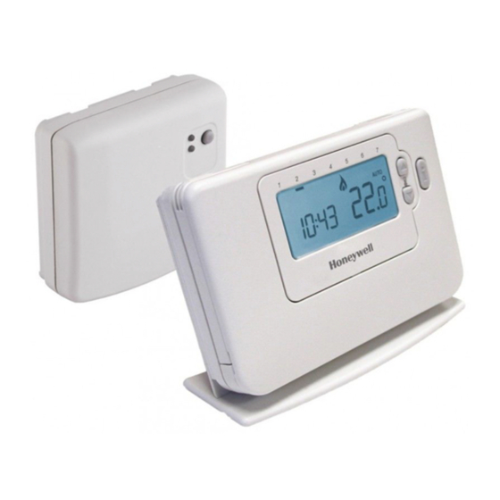
The Honeywell CM700 Wireless (CM727 or
CM721) is a modern wireless programmable
room thermostat based on Honeywell's proven
programming philosophy. To further improve the
ease of use, this product includes a large LCD
display with backlighting to assist customers
during daily use.
The CM727/721 room thermostat communicates
with the BDR91 relay box on an 868MHz Radio
Frequency (RF) band to control a single heating
system component such as a boiler, pump or
zone valve. Neither product will communicate with
other RF products that use different frequencies or
communication protocols.
Note: The RF link between the individual room
thermostat (CM727/721) and relay box (BDR91)
in system packs provided by Honeywell is pre-
configured at the factory and therefore SHOULD
be installed at the same site. This makes the
installation process fast and easy, but if products
from individual system packs are separated, or
mixed with other pre-configured system packs
during installations please refer to section 5.1
Binding / Rebinding Procedure to bind the desired
units together and allow them to communicate with
each other.
Table of Contents
Section
1) Installation Information ................................. 2
2) Installing the CM700 Wireless System ......... 3
............................................... 4
................................................ 5
3) Basic Operation of the System ..................... 6
....................................... 6
4) Installer Mode ................................................. 6
5) Additional Installation Information ............. 10
........................................ 10
6) Trouble Shooting .......................................... 11
........................................ 11
Page
................................... 3
........................ 4
........................ 4
................. 5
............................. 6
...................................... 6
................................... 7
............ 7
.. 8
.. 8
............................... 9
..... 9
.................. 10
...................... 10
................................. 11
50039990-003 A
Advertisement
Table of Contents

Related Manuals for Honeywell CM720


Summary of Contents for Honeywell CM720
-
Page 1: Table Of Contents
Note: The RF link between the individual room ........6 3.1 Automatic Operation thermostat (CM727/721) and relay box (BDR91) in system packs provided by Honeywell is pre- ......6 3.2 Temporary Manual Override configured at the factory and therefore SHOULD ........ -
Page 2: Installation Information
1) Installation Information As these products communicate using RF technology special care must be taken during installation. The location of the RF components as well as the building structure may influence performance of the RF system. To assure system reliability, please review and apply the information given below. Within a typical residential building the two products should communicate reliably within a 30m range. -
Page 3: Installing The Cm700 Wireless System
2) Installing the CM700 Wireless System Please follow the illustrations and information below in sequence to install the relay box and room thermostat correctly. For applications other than gas boilers, enabling special features and to see what other system options are available refer to section 4) Installer Mode. 2.1 Installing the Relay box The Relay Box is a RF device. -
Page 4: Installing The Room Thermostat
2.2 Installing the Room Thermostat 2.2.1 Power Up Installing the Batteries: a. Lift up the front cover of the thermostat to reveal the battery cover and product controls. b. Remove the battery cover by pressing down and sliding out. c. Insert the 2 x AA LR6 Alkaline Batteries supplied with the thermostat, ensuring the correct orientation (see ‘Controls Layout’... -
Page 5: Locating The Room Thermostat
2.2.3 Locating the Room Thermostat While still in the Test Mode, as described in section 2.2.2, the room thermostat should be located taking the following into consideration and reviewing the illustrations below: 1. Find a suitable location where the signal transmission is reliable. Reliable transmission is indicated when the relay box is flashing the green LED every 6 seconds. -
Page 6: Basic Operation Of The System
3) Basic Operation of the System 3.1 Automatic Operation BDR91 Relay box The relay box receives the heat demand (0- 100%) signal from the room thermostat. The room thermostat will display the symbol on the LCD display whenever more heat is required. Depending on the demand the relay box will switch the heating Push button and relay status LED’s... -
Page 7: Entering Installer Mode
4.1 Entering the Installer Mode 1. Press the OFF button. 2. Press and hold the button and the two DATE/ MANAUTO PROGRAM buttons together. COPY AUTO 3. The unit will display the first parameter of installer parameter group category 1 (from Parameter No. -
Page 8: Using The Room Thermostat For Specific Applications
4.3 Using the Room Thermostat for Specific Applications The CM727/721 RF room thermostat is a versatile controller that can be used to control many different applications. For most typical applications, like wall-hung gas fired combination boiler control or zone valve control, no adjustments from the factory settings are required. For other applications, like controlling an oil burner, the best system performance can be achieved by modifying selected parameters of the room thermostat in the Installer mode. -
Page 9: Installer Parameters Table
4.5 Installer Parameters Table 4.5.1 Category 1 - Room Thermostat Settings Parameter Parameter Factory Default Setting Optional Setting Category 1 Parameters – Room Thermostat Settings Display Description Display Description AM-PM / 24hr 1:CL 12 hr – AM/PM clock 24 hr clock display format Display display format Reset Time/ Temp... -
Page 10: Category 2 - System Settings
4.5.2 Category 2 - System Settings Parameter Parameter Factory Default Setting Optional Setting Category 2 Parameters – System Settings (press the button to access this category) Display Description Display Description Minimum boiler 1:Ot 1 minute minimum 2 to 5 Selection of 2, 3, 4 or 5 minutes ON time ON time minimum ON time... -
Page 11: Trouble Shooting
6) Trouble Shooting 6.1 Trouble Shooting Guide Symptom (Fault Possible Cause Remedy Message) The room thermostat This is normal operation. The relay box cycles Using the button change the the relay on and off for times proportional to temperature setpoint by a few degrees. displays the symbol but the demand signal (0-100%) from the room... - Page 12 Directive 1999/5/EC, 2006/95/EC and 2004/108/EC. Manufactured for and on behalf of the Environmental and Combustion Controls Division of Honeywell Technologies Sàrl, ACS-ECC EMEA, Z.A. La Pièce 16, 1180 Rolle, Switzerland by its Authorised Representative Honeywell International Inc.