Table of Contents
Advertisement
Quick Links
Service Manual
Spray Unit
ESH150–3PE~400V
Issue 1.0 30/05/22
Ref. NR-000144-ENG
Before preparing the unit and starting it up, please take the time to read all
the technical and safety instructions in this manual. It is essential that you
follow these instructions carefully so that you can handle and use the unit
properly. These instructions are intended to maximize user safety and
avoid malfunctions deriving from the incorrect use of the unit.
Advertisement
Table of Contents

Related Manuals for GAMA ESH150-3PE

Summary of Contents for GAMA ESH150-3PE
- Page 1 Service Manual Spray Unit ESH150–3PE~400V Issue 1.0 30/05/22 Ref. NR-000144-ENG Before preparing the unit and starting it up, please take the time to read all the technical and safety instructions in this manual. It is essential that you follow these instructions carefully so that you can handle and use the unit properly.
-
Page 2: Warranty
ESH150–3PE~400V Service manual WARRANTY HI-TECH SPRAY EQUIPMENT, S. A. (hereinafter “HI-TECH”) grants this Limited Guarantee to the original buyer (hereinafter the “Client”) for the unit and the original accessories given with the unit (hereinafter the “Product”) against any fault in the design, materials or manufacture of the Product at the time of the first purchase by the user and for a duration of two (2) years thereafter. -
Page 3: Safety And Handling
ESH150–3PE~400V Service Manual SAFETY AND HANDLING The equipment described in this manual has been designed and manufactured in compliance with the following European Directives, following as application guide the harmonized standards detailed and in conformity with the relevant UK Statutory Instruments (and their amendments): Directive 2006/42/EC on machinery (UK Supply of Machinery (Safety) Regulations 2008) UNE EN 12100:2012 (BS EN ISO 12100:2010) Directive 2014/30/EU on electromagnetic compatibility (UK Electromagnetic Compatibility... - Page 4 ESH150–3PE~400V Service manual Electrical products cannot be thrown out with the rubbish. They must be taken to a dedicated collection point for an environmentally sound disposal in accordance with local regulations. You must contact your local collective or retailer for information about recycling.
- Page 5 ESH150–3PE~400V Service Manual When working with the unit, it is essential that you wear suitable clothing and personal protective equipment including but not limited to gloves, protective goggles, safety footwear and face masks. Use breathing equipment when working with the unit in enclosed spaces or in areas with insufficient ventilation.
-
Page 6: Characteristics
ESH150–3PE~400V Service manual CHARACTERISTICS The easy spray-H proportioning unit is designed for the application of polyurea chemical systems for polyurethane foaming and certain two-component epoxy systems. Principal heating system Consists of two independent heaters without gaskets. Each heater has two 900 W/1500 W heating elements delivering total power of 1800 W / 3000 W, and the necessary control and safety mechanisms for the correct operation of the system. -
Page 7: Technical Specifications
ESH150–3PE~400V Service Manual TECHNICAL SPECIFICATIONS Electrical Voltage: ________________________________________________________________ 400V Frequency: ____________________________________________________________ 50/60Hz Connections: _________________________________________________________ 3PE~400 V Motor power: ______________________________________________________________ 3 kW Heater power: _____________________________________________________ 3.6 kW / 6 kW Hoses power: ________________________________________________ 3 kW / 1,6 kW / - kW Max. - Page 8 ESH150–3PE~400V Service manual To order suitable spare parts, check the correct elements that equip your machine. 8/56 Issue 1.0 Ref. NR-000144-ENG http://www.gamapur.com/...
-
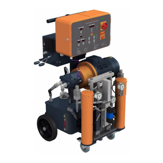
Page 9: Overniew
ESH150–3PE~400V Service Manual OVERNIEW . General view Figure 1 9/56 Issue 1.0 Ref. NR-000144-ENG http://www.gamapur.com/... - Page 10 ESH150–3PE~400V Service manual 1. Isocyanate intake 3/4"BSP Threaded Inlet connection chemical component “A”. 2. Polyol intake 3/4"BSP Threaded Inlet connection chemical component “R”. 3. Isocyanate output manifold Distributor Iso hose connection. 4. Polyol output manifold Distributor Pol hose connection. 5. Heated Hoses with transformers Keeps spray products at the right temperature in hoses.
- Page 11 ESH150–3PE~400V Service Manual NORMAL or RETRACT commands must be active before you can adjust the pressure of the hydraulic circuit. The hydraulic circuit should be regulated to ensure that the unit’s output pressure never exceeds the working pressure of the product hoses fitted to the unit.
- Page 12 ESH150–3PE~400V Service manual 32. Isocyanate tank (OPTIONAL) Contains chemical component “A”. Capacity 30 litres. 33. Polyol tank (OPTIONAL) Contains chemical component “R”. Capacity 30 litres. 34. Isocyanate recirculation valve (OPTIONAL recirculation hoses only) Enables selection between recirculation and spray for the isocyanate circuit. 35.
-
Page 13: Control Panel
ESH150–3PE~400V Service Manual CONTROL PANEL . Control panel Figure 2 The control panel enables you to set the optimum operating conditions for the characteristics and requirements of the products dispensed. Press the MODE button to enter the desired settings for temperature, intensity and number of cycles to run. The selected parameter remains flashing for a few seconds, allowing you to change the values by touching the UP / DOWN buttons. - Page 14 ESH150–3PE~400V Service manual Main Power switch Turns the electric supply to the control panel on and off. It must be turned ON for any operation to be performed with the unit. When turned ON, the green pilot at the top of the switch will come Hoses Hose heating control can be automatic when a temperature control sensor is used for direct temperature control, or manual where no...
- Page 15 ESH150–3PE~400V Service Manual The sequence for entering commands is as follows: • First we set the temperature of the ISO and POL heaters. • Next, we set the temperature of the ISO hoses. • Then we set the hose current consumption in amps. •...
- Page 16 ESH150–3PE~400V Service manual Heaters This display shows the temperatures in the isocyanate (ISO) and polyol (RESIN) heaters. To enter new temperature settings, press the MODE button, select the desired temperature by pressing the UP/DOWN buttons and press the MODE button again to confirm the selected value.
- Page 17 ESH150–3PE~400V Service Manual For machines with different product tanks or pumps, you must perform the calculation for each product and program the most unfavorable result (the result with the least number of cycles). When the counter reaches zero the machine stops in order not to pump air from the tanks into the system and alerting the lack of product in the tanks.
-
Page 18: Alarms
ESH150–3PE~400V Service manual ALARMS In the event of a malfunction affecting the operation of the unit, it emits an audio signal and shows an alarm code on the COUNTER/CONTADOR display. An alarm cannot be cleared until the problem which caused it has been resolved. After clearing the alarm, press the MODE button. - Page 19 ESH150–3PE~400V Service Manual Hose heating system malfunction (CONTROL/POWER cut-out) • Replace the faulty triac. 000000 Preselected cycles completed (solenoid valve cut-out) • Press the MODE button to reset the counter. • Set the cycle selector to zero. Disconnect the unit from the power supply before opening the electrical console.
-
Page 20: Method Of Threaded Union Of The Hoses
ESH150–3PE~400V Service manual METHOD OF THREADED UNION OF THE HOSES Follow the torques for threaded joints listed in Table 1 according to thread sizes of hose fittings to ensure their proper assembly. There is also an alternative procedure to obtain an equivalent torque without using special tools: joint both ends of the hoses to be connected, tighten a swivel nut by hand (without using spanner) until there is resistance... -
Page 21: Preparing The Unit For Operation
ESH150–3PE~400V Service Manual PREPARING THE UNIT FOR OPERATION WARNING! Use suitable protective gear and follow the safety recommendations of the suppliers of the chemical components when preparing or working with the unit. HI-TECH provides a set of tools and accessories necessary for the assembly of the machine. The set is composed of the following elements: Item DESCRIPTION... - Page 22 ESH150–3PE~400V Service manual Use the proper size of cable according to the voltage, current and maximum power required by the Unit. The sizing of the cable is calculated for a length of 25m, for longer lengths you must recalculate the appropriate section. 23 A @ 3PE~400V Cable Section 6 mm Make sure the power cable is disconnected from the mains source before connecting it...
-
Page 23: Figure 3. Hose Coupling Method
ESH150–3PE~400V Service Manual The hoses have been subjected to a vacuum-drying treatment and are delivered with their ends joined to prevent humidity from entering them. Do not separate them until the moment they are to be fitted to the unit. Proceed as follows to prepare the unit: d) Remove the front protective covering from the pump guides and fill the lube reservoir of the isocyanate pump with DOTP... -
Page 24: Preparation (Units With Heated Hose & Transformer)
ESH150–3PE~400V Service manual Preparation (units with heated hose & transformer) Each section of heated hose set features one connector for supply voltage and one connector for TCS temperature control. WARNING! Use suitable protective gear and follow the safety recommendations of the suppliers of the chemical components when preparing or working with the unit. - Page 25 ESH150–3PE~400V Service Manual A good practice is to add some dielectric grease to the ID of the connector. Repeat the same steps to connect the “fast lock” that you will find in the middle hose connections. b) Connect the rest of the product hoses to complete the required length.
-
Page 26: Purge Method (Units With Heated Hose & Transformer)
ESH150–3PE~400V Service manual Proceed to install the transfer pumps (if applicable) paying special attention to connect each pump to “its” respective product, as changing the pumps would cause a reaction in the products inside them and make them useless. Identifying each pump with a tape of the same color as that of the hoses (blue for the Polyol pump and red for the Isocyanate pump) might be a good method for avoiding errors in connection. -
Page 27: Preparation (Only For Units With Tanks & Recirculation Hose)
ESH150–3PE~400V Service Manual Preparation (only for units with tanks & recirculation hose) WARNING! Use suitable protective gear and follow the safety recommendations of the suppliers of the chemical components when preparing or working with the unit. NOTE: To ensure the correct operation of the unit, the electrical power supply must meet the specifications given on p 7 of this manual and on the unit’s rating plate. -
Page 28: Purge Method (Only For Units With Tanks & Recirculation Hose)
ESH150–3PE~400V Service manual Purge method (only for units with tanks & recirculation hose) Before using the unit, all air pockets and residual oil from in-factory testing must be eliminated. To purge the full circuit, proceed as follows: a) Disconnect the isocyanate and polyol recirculation tubes and place them in separate waste recipients. - Page 29 ESH150–3PE~400V Service Manual The hydraulic circuit should be regulated to ensure that the unit’s output pressure never exceeds the working pressure of the product hoses fitted to the unit. Allow the air and oil to escape from the recirculation tubes until there is no more residual oil and the air has stopped gurgling.
-
Page 30: Power-Up Procedure (Integrated Transformer)
ESH150–3PE~400V Service manual POWER-UP PROCEDURE (INTEGRATED TRANSFORMER) Follow the recommended procedure in the indicated order. PRECAUTION! The start-up procedures assume that all the necessary adjustments have been correctly performed. a) Check the state of the DOTP plasticizing oil in the lubrication bowl of the Isocyanate pump. -
Page 31: Power-Up Procedure (Hoses With Recirculation)
ESH150–3PE~400V Service Manual m) Connect the air supply to the gun; open the manual valves of each product; make a test projection and check the pressures on the product gages. If the projection test is correct and the pressures remain equal, proceed with the application POWER-UP PROCEDURE (HOSES WITH RECIRCULATION) Follow the recommended procedure, in the sequence given, to power-up the unit: WARNING! - Page 32 ESH150–3PE~400V Service manual WARNING! To avoid excess pressure in the heating hoses, wait for the products contained in the hoses to reach the required temperature before starting the hydraulic system. m) Press the MOTOR button. The LED will light up. n) Press the NORMAL button.
-
Page 33: Power-Down
ESH150–3PE~400V Service Manual POWER-DOWN Follow the recommended procedure, in the sequence given, to power-down the unit when work is stopped for the day: a) Press the RETRACT button. The LED will light up. b) Operate the gun, spraying into a waste recipient until the isocyanate proportioning pump is in the retracted position and the spray angle begins to decrease. -
Page 34: Cleaning Procedure (Heated Hoses With Transformer)
ESH150–3PE~400V Service manual CLEANING PROCEDURE (HEATED HOSES WITH TRANSFORMER) PRECAUTION! The unit includes components that reach temperatures that are liable to cause burns. The hot parts of the unit must not be handled until they have cooled. To avoid possible contamination, the circuits of the unit must previously be cleaned (pumps, heaters, and hoses) whenever applications have to be made that require a change of components. -
Page 35: Cleaning Procedure (Recirculation Hoses Tanks)
ESH150–3PE~400V Service Manual CLEANING PROCEDURE (RECIRCULATION HOSES TANKS) WARNING! This unit includes parts which reach temperatures likely to cause burns. Do not touch or handle the hot parts of the unit until they have cooled down. To avoid possible contamination, all the unit’s circuits (pumps, heaters and hoses) must be cleaned before applications which require a change of components. - Page 36 ESH150–3PE~400V Service manual x) Disconnect the recirculation tubes from the isocyanate and polyol tanks and place them in separate waste recipients. Open the recirculation valves located under each product tank and make sure the taps on the coupling block are closed. z) Rotate the power switch to the ON position.
-
Page 37: Temporary Layoff Of The Unit (Heated Hoses With Transformer)
ESH150–3PE~400V Service Manual TEMPORARY LAYOFF OF THE UNIT (HEATED HOSES WITH TRANSFORMER) WARNING! This unit includes parts which reach temperatures likely to cause burns. Do not touch or handle the hot parts of the unit until they have cooled down. When the unit is to be out of service for over FOUR weeks, you must replace the products contained in the unit with DOTP plasticizer. -
Page 38: Temporary Layoff Of The Unit (Recirculation Hoses Tanks)
ESH150–3PE~400V Service manual TEMPORARY LAYOFF OF THE UNIT (RECIRCULATION HOSES TANKS) WARNING! This unit includes parts which reach temperatures likely to cause burns. Do not touch or handle the hot parts of the unit until they have cooled down. When the unit is to be out of service for over FOUR weeks, you must replace the products contained in the unit with DOTP plasticizer. -
Page 39: Malfunction
ESH150–3PE~400V Service Manual MALFUNCTION The easy spray-H unit has been designed and built to operate in severe working conditions. It will work with a high degree of reliability on condition that it is used and maintained correctly. This section contains information on the possible causes of malfunctions in the unit. Most problems with the unit can be detected and resolved using the information provided in this section. -
Page 40: Heaters
ESH150–3PE~400V Service manual Heaters WARNING! Before attempting to fix any kind of malfunction, make sure that no buttons are lit on the electrical panel, that the power switch is in the OFF position and that the unit is disconnected from the power supply. Never open the electrical console when the unit is connected to the power supply. -
Page 41: Table 2. Elements Values List
ESH150–3PE~400V Service Manual To check the elements, proceed as follows: With the power switch in the OFF position, use a tester to check the total resistance of the heater, which should be that indicated in the table according to the power, voltage and number for each installed heater elements, a higher value would indicate that one or more elements are faulty. -
Page 42: Hose Heating
ESH150–3PE~400V Service manual Hose heating WARNING! Before attempting to fix any kind of malfunction, make sure that no buttons are lit on the electrical panel, that the power switch is in the OFF position and that the unit is disconnected from the power supply. Never open the electrical console when the unit is connected to the power supply. - Page 43 ESH150–3PE~400V Service Manual Triac This determines that the triac is faulty when all of the previous checks have been correct. Replace the triac if is fails to work correctly. Hose Heating Components With the general switch turned off, make sure the hose connections and the electrical connections between the hoses and the unit are correct and tight.
-
Page 44: Proportioning Pumps
ESH150–3PE~400V Service manual Proportioning pumps WARNING! Before attempting to fix any kind of malfunction, make sure the power switch is in the OFF position and that the unit is disconnected from the power supply. Never open the electrical console when the unit is connected to the power supply. Proportioning pumps work under pressure. - Page 45 ESH150–3PE~400V Service Manual To ascertain whether the pressure imbalance is caused by an obstruction or by a problem in the pumping system, operate the spray gun and check the reading on the pressure gauge of the missing component. Compare this reading with the pressure indicated on the other component’s pressure gauge: if the pressure of the missing component is higher, the pressure imbalance is caused by an obstruction;...
-
Page 46: Hydraulic Drive
ESH150–3PE~400V Service manual Hydraulic drive WARNING! Before attempting to fix any kind of malfunction, make sure that no lights are lit on the control panel, the power switch is set to the OFF position, and the unit is disconnected from the power supply. Never open the electrical console when the unit is connected to the power supply. -
Page 47: Maintenance
ESH150–3PE~400V Service Manual MAINTENANCE To obtain optimum performance from the easy spray-H unit you must perform certain maintenance operations on a daily or regular basis. To avoid bodily damage caused by the incorrect handling of the substances and solvents used with this unit, read carefully the safety information provided by their suppliers. -
Page 48: Heaters
ESH150–3PE~400V Service manual Heaters WARNING! Before proceeding to any kind of maintenance work, make sure the power switch is in the OFF position and that the unit is disconnected from the power supply. Never open the electrical console when the unit is connected to the power supply. Heaters can reach high temperatures. -
Page 49: Proportioning Pumps
ESH150–3PE~400V Service Manual Proportioning pumps WARNING! Before proceeding with maintenance works, make sure that all push buttons are switched off, the general switch is in the off position, and the Unit is unplugged from the power supply. Never handle the control panel interior while the Unit is plugged into the electricity grid. - Page 50 ESH150–3PE~400V Service manual First, assemble the rod set with the piston and all its components. Ensure that the piston seal lips are facing upwards. Insert the assembled piston set inside the sleeve with the specific tool (1) (see Table 3 on page.51) Once you have inserted piston...
-
Page 51: Table 3. List Of Tools
ESH150–3PE~400V Service Manual List of Tools Table 3. Tool (1) Tool (2) Tool (3) Tool (4) SIZE #4.5 HT-00034 HT-00116 HT-00119 HT-00121 #7.6 HT-00031 HT-00117 HT-00120 HT-00122 Note: These tools are not supplied with the machine, they are optional upon request. 51/56 Issue 1.0 Ref. -
Page 52: Product Intake Filters
ESH150–3PE~400V Service manual Product intake filters Filter bodies are fitted with an inner mesh which prevents solid particles from entering the unit and potentially interfering with the operation of the ball valves when the product is taken into the unit. Filters should be inspected and cleaned daily as part of the power-up routine. Replace the inner mesh if necessary. -
Page 53: Isocyanate Pump Lubrication System
ESH150–3PE~400V Service Manual Isocyanate pump lubrication system Inspect the isocyanate pump lube reservoir every day and check the condition of the DOTP plasticizer oil it contains. Replace the oil if it is discoloured or exhibits signs of solidification. DOTP oil solidifies as a consequence of moisture absorption. The frequency of oil changes depends on the working conditions. -
Page 54: Hydraulic Drive
ESH150–3PE~400V Service manual Hydraulic drive WARNING! Before proceeding to any kind of maintenance work, make sure all lights on the control panel are off, the power switch is in the OFF position, and the unit is disconnected from the power supply. Never open the electrical console when the unit is connected to the power supply. -
Page 55: Table Of Contents
ESH150–3PE~400V Service Manual CONTENTS Warranty _____________________________________________________ 2 Safety and handling ____________________________________________ 3 Characteristics ________________________________________________ 6 Principal heating system ___________________________________________________ 6 Hose heating system ______________________________________________________ 6 Proportioning pumps ______________________________________________________ 6 Technical specifications ________________________________________ 7 Electrical _______________________________________________________________ 7 Mechanical ______________________________________________________________ 7 Acoustic ________________________________________________________________ 7 oVERNIEW ___________________________________________________ 9 Control panel ________________________________________________ 13 Alarms ______________________________________________________ 18... -
Page 56: List Of Illustrations
ESH150–3PE~400V Service manual Proportioning pumps _______________________________________________________ 49 Product intake filters________________________________________________________ 52 Isocyanate pump lubrication system ___________________________________________ 53 Hydraulic drive ____________________________________________________________ 54 Contents ____________________________________________________ 55 List of illustrations ____________________________________________ 56 List of Tables ________________________________________________ 56 LIST OF ILLUSTRATIONS Figure 1. General view __________________________________________ 9 Figure 2.