Table of Contents
Advertisement
Advertisement
Table of Contents

Related Manuals for Mitsubishi STERAPORE 5600 FF Series


Summary of Contents for Mitsubishi STERAPORE 5600 FF Series
- Page 1 STERAPORE 5600 Series (FF) Instruction Manual 1/59 2nd Edition, July 2015...
- Page 2 Introduction This instruction manual describes the outlines, designs, installation, operation, and maintenance of the STERAPORE 5600 Series (FF). Please read this manual completely before using this product, and use the product safely and appropriately. Keep this manual in a safe place after reading it. Please confirm the specifications of the products covered by this instruction manual in [Chapter 10 Specifications].
-
Page 3: Table Of Contents
Table of Contents Table of Contents CHAPTER 1 MBR COMPOSITION AND PLACEMENT ............6 MBR ..........................6 VERVIEW OF MBR E ...................... 8 OMPOSITION OF QUIPMENT MBR P ..........................10 LACEMENT CHAPTER 2 FILTRATION AND MEMBRANE SCOUR AERATION ........12 ............................ - Page 4 This symbol indicates actions that must be performed. Mitsubishi Rayon shall not bear any responsibility for any damage to human lives, property and the like caused by any systems in which this product is included due to improper use that does not follow this instruction manual.
- Page 5 For Safe Use Do not mix sodium hypochlorite (NaClO) and acid under any circumstances. Doing so releases chlorine gas, which is very dangerous. Be sure to take this into account when designing the system. As the modules are very heavy, when using forklifts and cranes make sure that all apparatus is inspected and certified, and all operators are certified.
-
Page 6: Chapter 1 Mbr Composition And Placement
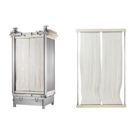
Chapter 1 MBR Composition and Placement Chapter 1 MBR Composition and Placement STERAPORE 5600 Series (FF) hollow fiber membrane modules are submerged membrane modules used for MBR (membrane bioreactor) wastewater treatment. Install the products in a membrane tank and use them for solid-liquid separation. - Page 7 Chapter 1 MBR Composition and Placement There are two types of MBR system. Integrated MBR systems which place membrane modules in aeration tanks. Separate MBR systems which place membrane modules in separate membrane tanks. Figure 1-2 shows schematic diagrams for both. Figure 1-2 Schematic Diagrams of the Integrated MBR System and Separate MBR System 7/59 STERAPORE 5600 Series (FF) Instruction Manual...
-
Page 8: Composition Of Mbr Equipment
Chapter 1 MBR Composition and Placement Composition of MBR Equipment The MBR system is composed of various components, including membrane modules, chemical cleaning equipment, permeate pumps, blowers, etc. Figure 1-3 shows an example schematic diagram of an MBR system. Figure 1-3 Schematic Diagram of an MBR System (Example) 1-2-1 Roles of Main Components and Tanks in the MBR System ①... - Page 9 Chapter 1 MBR Composition and Placement ④ Treated water tank This is a tank used to store treated water. It sometimes serves as a dilution water tank. When necessary, sodium hypochlorite is added to the water in this tank to disinfect it before it is discharged. ⑤...
-
Page 10: Mbr Placement
Chapter 1 MBR Composition and Placement MBR Placement This section describes module layout in the membrane tank and required water depth. C AUT IO N When using this product, ensure that all of the installation requirements below are met. If these requirements are not met, the product will not function as indicated in the specifications, and/or may deteriorate or become damaged. - Page 11 Chapter 1 MBR Composition and Placement 1-3-2 Minimum Water Depth Leave space above the modules when installing them in the membrane tank to allow swirl flow to be evenly created. See Table 1-1 for minimum water depth for each module. C AUT IO N A failure to secure the minimum water depth will prevent stable operation.
-
Page 12: Filtration And Membrane Scour Aeration
Chapter 2 Filtration and Membrane Scour Aeration Chapter 2 Filtration and Membrane Scour Aeration Filtration 2-1-1 Notes Regarding Filtration Design ● Incorporate an emergency filtration-stop function into the system. If the air for cleaning the membrane module stops, continuing filtration results in the fixation of sludge and a rise in trans membrane pressure. - Page 13 Chapter 2 Filtration and Membrane Scour Aeration 2-1-3 Permeate Pumps Determine the pump specifications on the basis of flow rate, pump location, actual pump head, pipe resistance, and so on. RE F ER E NC E Choosing a self-suction pump as the permeate pump makes it easy to maintain suction pressure during intermittent filtration operation.
-
Page 14: Membrane Scour Aeration Devices
Chapter 2 Filtration and Membrane Scour Aeration Membrane Scour Aeration Devices The aeration flow rate for module cleaning is 75 to 150 Nm •h) (standard aeration flow rate: 125 •h))*. Calculated based on the area to be aerated (upflow section). ... -
Page 15: Cleaning The Diffuser
Chapter 2 Filtration and Membrane Scour Aeration Cleaning the Diffuser The FB diffusers embedded in the module are SUS perforated pipe diffusers. When SUS perforated pipe diffusers are used for long periods of time, sludge may enter the diffusers, dry, and block the holes. Therefore they must be cleaned regularly to stop the sludge from drying. - Page 16 Chapter 2 Filtration and Membrane Scour Aeration C AUT IO N When designing the piping, make sure that tank water flowing backward through the diffuser does not flow into the blower while the blower is stopped. When feeding clear water into the diffuser, take sufficient care not to let water flow backward into the blower.
-
Page 17: Chapter 3 Chemical Cleaning
Chapter 3 Chemical Cleaning Chapter 3 Chemical Cleaning This section describes cleaning equipment such as chemical tanks and chemical pumps and cleaning procedures. WAR NI NG * Handle each chemical according to its SDS Wear protective clothing when handling elements and modules. Be sure to wear protective clothing such as goggles and rubber gloves when handling chemicals such as sodium hypochlorite (NaClO) used for membrane cleaning or acid. - Page 18 Chapter 3 Chemical Cleaning 3-1-1 Cleaning Methods ● Maintenance cleaning Maintenance cleaning is performed to remove membrane surface fouling regularly to inhibit thickening of the cake layer and prevent the trans membrane pressure from rising for stable operation of the product.
- Page 19 Chapter 3 Chemical Cleaning ● Chemical soak cleaning (Off line cleaning) Chemical soak cleaning is performed when recovery cleaning has not restored the trans membrane pressure, or when sludge has adhered between membranes due to device problems or other reasons (clogging).
- Page 20 Chapter 3 Chemical Cleaning Figure 3-1 Diagram of a Module Immersed in a Washing tank Figure 3-2 Diagram of a Membrane Element Immersed in a Washing Tank 20/59 STERAPORE 5600 Series (FF) Instruction Manual...
- Page 21 Chapter 3 Chemical Cleaning 3-1-2 Acid Cleaning Although NaClO cleaning effectively removes organic contamination, it has no effect on inorganic contamination. Cleaning only with NaClO will result in inorganic matter causing a rise in trans membrane pressure. Perform acid cleaning once a year if the product is used for municipal wastewater treatment. Either the same process as recovery cleaning or chemical soak cleaning process is used in acid cleaning.
- Page 22 Chapter 3 Chemical Cleaning 3-1-3 Precautions Regarding Chemical Cleaning ● Handling Chemicals Chemicals such as NaClO, and oxalic, citric, sulfuric, and hydrochloric acid are used in chemical cleaning. C AUT IO N Wear safety goggles and protective gloves and handle chemicals appropriately with due consideration for the environment and safety by referring to SDS and other relevant information.
- Page 23 Chapter 3 Chemical Cleaning ● Releasing Air From Pipes for Maintenance and Recovery Cleaning If air remains in pipes for cleaning, air lock can occur during chemical cleaning, preventing chemical solutions from being distributed throughout the hollow fiber membrane. Be sure to release air from the cleaning line.
- Page 24 Chapter 3 Chemical Cleaning ● Chemical Soak Cleaning WAR NI NG After lifting the module, rinse it under running water and remove any adhered sludge before immersing it. Do not use a high pressure washer to clean elements as it may damage the membrane.
-
Page 25: Cleaning Equipment
Chapter 3 Chemical Cleaning Cleaning Equipment For maintenance cleaning and recovery cleaning, a chemical tank, chemical pump, dilution water tank, and dilution water pump are required. Figure 3-4 shows a schematic diagram of cleaning equipment. Refer to the example calculations in 3-2-1 and select pumps and instruments so the amount of chemical solution can be adjusted. - Page 26 Chapter 3 Chemical Cleaning 3-2-1 Device and Equipment Design ● Chemical tank (NaClO storage tank) This is a tank used to store chemicals (NaClO). NaClO is corrosive. ■Design example Tank capacity: The amount used in 1 to 2 months (calculated including maintenance cleaning and recovery cleaning) Tank material: PE, FRP, etc.
- Page 27 Chapter 3 Chemical Cleaning ■Example of a calculation for the flow rate of a chemical pump per 56M0800FF unit (excluding the amount corresponding to the capacity of the guide pipe) Assume that the concentration of undiluted NaClO solution is 12 % and that its specific gravity is 1.19. ...
-
Page 28: Chapter 4 Pretreatment
Chapter 4 Pretreatment Chapter 4 Pretreatment Pretreatment The aims of pretreatment are as follows. To prevent inflow of raw water that may inhibit the MBR system's functions and damage MBR facilities. To use devices safely and stably. To effectively carry out biological processes. This section describes these pretreatment procedures. - Page 29 Chapter 4 Pretreatment ● Water temperature If raw water temperature or aeration tank temperature rises to 40°C or above, biological processing performance declines. In particular, nitrification using nitrification bacteria is susceptible to changes in water temperature. The rate of reaction decreases in low temperatures and nitrification bacteria are killed at high temperatures.
-
Page 30: Activated Sludge
If an antifoaming agent is to be put into aeration tank due to sludge foaming, use a high grade alcohol, ether, or ester antifoaming agent. Our recommended antifoaming agent is DIAFLOC AF102 (made by Mitsubishi Rayon Co.,Ltd.) If you are considering purchasing this product, please contact our sales representative. -
Page 31: Transport And Installation
Chapter 5 Transport and Installation Chapter 5 Transport and Installation This section describes handling instructions concerning transport, storage, transfer, and installation of elements and modules. Transport and Installation 5-1-1 Notes Regarding Packing and Transport Elements and modules must be kept at a temperature of 5 to 40°C when being transported. Use an air-conditioned or heated trailer if this requirement may not be met. - Page 32 Chapter 5 Transport and Installation Figure 5-2 Handling marks Table 5-1 Packaging Specifications for Membrane Elements and the Number of Stackable Elements Number Model Number Quantity Length Width Height(mm) Volume(m Gross No. of (pc) (mm) (mm) Weight weight Stackable (kg) (kg) elements *...
- Page 33 Chapter 5 Transport and Installation Figure 5-5 Module (diffuser part) Packaging 33/59 STERAPORE 5600 Series (FF) Instruction Manual...
- Page 34 Chapter 5 Transport and Installation 5-1-2 Notes Regarding Storage Store the products indoors in a dry condition and avoid exposure to rain and wind. Do not let unused elements become damp, as storing damp elements for a long period of time may cause mold growth and a decline in permeability.
- Page 35 Chapter 5 Transport and Installation 5-1-4 Confirmation Items before Installation Conduct thorough inspections and make records when carrying out the initial membrane installation work. Do not proceed to the module installation process until all preparations have been made. Confirm/carry out the following. ①...
- Page 36 Chapter 5 Transport and Installation 5-1-5 Installation Follow the procedure below to install modules. C AUT IO N Wear appropriate protective clothing including a helmet, a safety belt, safety shoes, and safety gloves. Use appropriate tools for tightening and loosening bolts and nuts, and handle them with due care. Assemble modules on a stable surface in order to prevent them from falling over.
- Page 37 Chapter 5 Transport and Installation Figure 5-6 Example of Module Installation Check that the modules are level. Install modules in a location with horizontality of 3 mm/1,000 mm or less. Placing modules on a surface which has a greater slope may result in uneven aeration and inadequate membrane scouring and cause membrane clogging.
-
Page 38: Procedures For Lifting Up Modules
Chapter 5 Transport and Installation Procedures for Lifting up Modules When lifting up modules, for instance, when delivering them for installation, installing them, or removing them for maintenance, appropriate construction machinery, tools, and a work plan are required to ensure safety and to prevent module damage. - Page 39 Chapter 5 Transport and Installation Table 5-2 Estimated Length of the Balance and Lifting Height Figure 5-8 Schematic Drawing of a Membrane Module's Lifting Lugs 39/59 STERAPORE 5600 Series (FF) Instruction Manual...
-
Page 40: Chapter 6 Operation
Chapter 6 Operation Chapter 6 Operation Commissioning Before starting water commissioning, be sure to do the following in preparation. Fill tanks with water. Fill tanks with clear river water or similar up to the design water level. Check the water gauge indication and for water gauge alarms. Record and adjust the actual water level indication on the water gauge when filling tanks with water to adjust the water gauge, and check for alarms. -
Page 41: Operation Management
Chapter 6 Operation Carry out comprehensive water commissioning. Feed water from the raw water tank or flow equalization tank to carry out commissioning of the entire system and confirm its operation. •d) and confirm and record trans membrane Successively change flux from 0.1 to 1.0 m pressure after each change. - Page 42 Chapter 6 Operation Figure 6-1 Schematic Diagram of an Example MBR System Using Recycled Nitrification Processing 42/59 STERAPORE 5600 Series (FF) Instruction Manual...
- Page 43 Chapter 6 Operation 6-2-2 Operation Management Procedures This section describes example management procedures for the septic tank of MBR systems using recycled nitrification processing. Inspection items and maintenance work are as indicated in Table 6-2. Important inspection items are screenings, DO, flux, trans membrane pressure, and the state of aeration. Maintenance inspection of these items to prevent problems leads to a reduction in running costs.
- Page 44 Chapter 6 Operation Equipment Inspection Item Normal State Maintenance and Inspection Sufficient amount of chlorinated Disinfection tank Check chlorinated compound Chlorinated compound (if solid chlorinated compound is compound replenishment used) At or above the specified volume NaClO tank State of remaining amount NaClO replenishment ...
- Page 45 Chapter 6 Operation Figure 6-2 Diagram of Operation Management Procedures 45/59 STERAPORE 5600 Series (FF) Instruction Manual...
- Page 46 Chapter 6 Operation 6-2-3 Operation Management Record Create an operation management recording sheet for routine maintenance. Keeping a record can be helpful in determining the cause of problems. An example of an operation management recording sheet is given in Figure 6-3. This check list is only an example.
-
Page 47: Mbr System Operation
Chapter 6 Operation MBR System Operation 6-3-1 Seeding Input Seeding is put into the MBR system when it starts up. Activated sludge from a plant which uses municipal wastewater as raw water and employs a screen with relatively small openings for pretreatment is suitable as seeding. Highly concentrated sludge such as return sludge is suitable when ease of transport and usability are considered. - Page 48 Chapter 6 Operation Start filtration operation. Start filtration operation after activating the anoxic tank mixer, the circulation pump, and the blower to mix water and sludge well. C AUT IO N For each device, ensure that the water level is at or above the minimum water level at which the device can be operated, and then activate the devices in order.
-
Page 49: Chapter 7 Troubleshooting
Chapter 7 Troubleshooting Chapter 7 Troubleshooting Troubleshooting: Examples Problems can be roughly classified into those related to devices and those related to effluent quality. It is important to respond promptly to problems when they arise. Examples of problems and responses to them are shown in Table 7-1 and Table 7-2(p.50). Table 7-1 Examples of Device Related Problems and Responses Inspection Problem... - Page 50 Chapter 7 Troubleshooting Table 7-2 Examples of Effluent Quality Related Problems and Responses Item Probable Cause(s) Response(s) Abnormal quality of incoming raw Check the quality of raw water. water. Decline in MLSS. Adjust amount of sludge extraction. Lack of aeration. Adjust the air flow rate to a proper value (proper value: DO >...
-
Page 51: Chapter 8 Maintenance
Chapter 8 Maintenance Chapter 8 Maintenance Membrane Repair Described below is the procedure for repairing membranes with epoxy resin adhesive when a hollow fiber membrane in the element is damaged during operation or sampled for analysis. First, prepare the following 3 items. ... -
Page 52: Diffuser Cleaning
Chapter 8 Maintenance Diffuser Cleaning This section describes the procedure for cleaning clogged SUS perforated pipe diffusers in modules to eliminate clogging substances. First, prepare the following protective clothing and tools. Helmet Safety belt Protective gloves Safety goggles ... -
Page 53: Procedure For Long-Term Storage Of Used Modules
Chapter 8 Maintenance Procedure for Long-term Storage of Used Modules Store modules used in the MBR system in a wet condition if they are to be stored for a long period of time. Fouling substances remain on the surface of hollow fiber membranes even if they have been washed with clean water and appear clean. -
Page 54: Chapter 9 Reference Materials
Chapter 9 Reference materials Chapter 9 Reference materials Glossary ● Hollow-fiber membrane Hollow-fiber membranes are membranes that have been molded into a hollow fiber shape. Membranes with a diameter larger than 5 mm are classified as tubular membranes. ● MBR (membrane bioreactor) (See p.6 “1-1 Overview of MBR”) MBR is a biological treatment process for solid-liquid separation of organic wastewater in which the final sedimentation tank used for activated sludge processing in conventional systems is replaced by membrane processing. - Page 55 Chapter 9 Reference materials ● Flux (See p.12 2-1-2 “Configuring Flux Settings”) Flux is the speed at which water permeates the membrane. It is calculated by dividing the filtration flow per unit time by the membrane surface area. It is also referred to as linear velocity (LV). •d) (reference value).
-
Page 56: List Of Consumables
Chapter 9 Reference materials List of Consumables A list of consumables is given in Table 9-1. Use this as a guide to when the consumables need replacing. As the life of each part differs according to raw water conditions, conditions of use, and the environment, inspect and check the items. -
Page 57: Chapter 10 Specifications
Chapter 10 Specifications Chapter 10 Specifications 10-1 Element Specifications Product specifications for membrane elements are given below. Specifications indicated in this manual may be subject to change without notice. Table 10-1 Element Specifications Item Unit Specifications - Element model number 56E0040SA Nominal membrane surface area -... -
Page 58: 10-2 Module Specifications
Chapter 10 Specifications 10-2 Module Specifications Product specifications for modules are given below. Specifications indicated in this manual may be subject to change without notice. Please select a hoist and other equipment for lifting modules while taking the weight of the module, chains and connecting pipes into account. - Page 59 STERAPORE 5600 Series (FF) Instruction Manual 2nd Edition, July 2015 ----------------------------------------For inquiries, please contact: MITSUBISHI RAYON AQUA SOLUTIONS CO., LTD. Membrane Department Membrane Division 10F Gate City Ohsaki East Tower, 1-11-2 Osaki, Shinagawa-ku, Tokyo, 141-0032, Japan TEL: 81-3-6748-7467 / FAX: 81-3-5487-7527...