Table of Contents
Advertisement
Quick Links
Advertisement
Table of Contents

Related Manuals for Yamaha YP20G


Summary of Contents for Yamaha YP20G
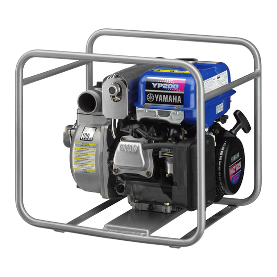
- Page 1 Water Pump OWNER’S MANUAL YP20G YP30G LIT-19626-01-35 9CB-28199-11...
- Page 3 AE00002 INTRODUCTION Congratulations on your purchase of your new Yamaha. This manual will provide you with a good basic understanding of the operation and maintenance of this machine. If you have any questions regarding the operation or maintenance of your machine, please consult a Yamaha dealer.
- Page 4 If there IS INVOLVED! is any question concerning this manu- al, please consult your Yamaha deal- 9 This manual should be considered a Failure to follow WARNING instructions could result in severe injury or death to...
-
Page 5: Table Of Contents
AE00041 CONTENTS WATER PUMP LIMITED PERIODIC MAINTENANCE ....15 MAINTENANCE CHART ....15 WARRANTY ..........1 SPARK PLUG INSPECTION....16 CARBURETOR ADJUSTMENT ..16 LOCATION OF IMPORTANT WATER LEAKAGE CHECK .....16 LABELS..........3 ENGINE OIL REPLACEMENT ..17 AIR FILTER ........18 FUEL COCK ........19 SAFETY INFORMATION.......4 FUEL TANK FILTER......19 EXHAUST FUMES ARE MUFFLER SCREEN AND SPARK POISONOUS ........4... -
Page 6: Water Pump Limited Warranty
CE00051* YAMAHA MOTOR CORPORATION, U.S.A. WATER PUMP LIMITED WARRANTY Yamaha Motor Corporation, U.S.A. hereby war- 2. Give notice to an authorized Yamaha water rants that Yamaha water pumps pur- pump dealer of any and all apparent defects chased from authorized... - Page 7 A. These terms are general and overlap each other in areas. Specific examples include: If your machine requires warranty service, Running the machine out of oil; lack of you must take it to any authorized Yamaha proper maintenance; operating water pump dealer within the continental machine with a broken or damaged part United States.
-
Page 8: Location Of Important Labels
T H I S L A B E L T O B E REMOVED B Y T H E U L T I M A T E P U R C H A S E R O N L Y ! zzzzz EMISSIONS COMPLIANCE PERIOD:CATEGORY A (EPA) YAMAHA MOTOR POWERED PRODUCTS CO.,LTD. – 3 –... -
Page 9: Safety Information
AE00071 SAFETY INFORMATION AE00072 EXHAUST FUMES ARE POISONOUS 9 Never operate the engine in a closed area or it may cause unconsciousness and death within a short time. Operate the engine in a well ventilated area. AE00075 FUEL IS HIGHLY FLAMMABLE AND POISONOUS 9 Always turn off the engine when refuelling. - Page 10 9 Keep the machine at least 1 m (3 ft) from buildings or other equipment, or the engine may overheat. a 1 m (3ft) 745-019a 9 Do not operate the engine with a dust cover. – 5 –...
-
Page 11: Control Function
AE00101 CONTROL FUNCTION AE00102 DESCRIPTION 1 Fuel tank 2 Fuel tank cap 3 Fuel cock 4 Air filter cover 5 Spark plug 6 Muffler 7 Choke lever 8 Engine switch 9 Oil filler cap 0 Oil drain plug q Recoil starter w Oil warning light e Throttle lever r Priming plug... -
Page 12: Water Hose Installation
9 Be sure the strainer is installed or pump dam- age will occur. Install the strainer A) 50 mm (2 in) suction port diameter for YP20G B) 80 mm (3 in) suction port diameter for YP30G both with filtering perforations 8 mm (0.31 in) or less in diameter. -
Page 13: Engine Switch
AE00124 ENGINE SWITCH The engine switch controls the ignition system. 1 “ON” Ignition circuit is switched on. The engine can be started. 2 “OFF” Ignition circuit is switched off. The engine will not run. CE00171 THROTTLE LEVER The throttle lever controls the engine speed. Move the throttle lever in direction 1 to decrease engine speed. -
Page 14: Pre-Operation Check
Fuel tank capacity: Total: 4.5 L (0.99 Imp gal, 1.19 US gal) Your Yamaha engine has been designed to use regu- lar unleaded gasoline with a pump octane number ((R + M)/2) of 86 or higher, or research octane number of 91 or higher. -
Page 15: Engine Oil
CE00222 ENGINE OIL Make sure the engine oil is between upper and lower levels. Add oil as necessary. Insert the oil level gauge in the filler hole without screwing it in. 1 Upper level 2 Lower level 700-103 Recommended oil: 0°C 25°C A YAMALUBE 4 (10W-30) or SAE 10W-30... - Page 16 NOTE: 9 Be sure the pump is placed on a firm place and as near to available water source as possible. 9 The higher the suction head is the more time will be required for priming with less discharge. – 11 –...
-
Page 17: Operation
CE00303 OPERATION NOTE: The water pump has been shipped without engine oil. Fill with oil or it will not start. 700-006a 1 Upper level CE00312 STARTING THE ENGINE Be sure the pump is filled up with water before starting the engine. 1. -
Page 18: Stopping The Engine
5. Pull slowly on the recoil starter until it is engaged, then pull it briskly. 6. After the engine starts, warm up the engine until the engine does not stop when the choke lever is returned to the operating position. 704-010 7. -
Page 19: Drain Of Water After Use
CE00383 DRAIN OF WATER AFTER USE Water inside casing freezes at below 0°C (32°F) in winter and thereby pump may possibly be broken. After use, drain water from drain port at bottom to store. – 14 –... -
Page 20: Periodic Maintenance
Fittings/Fasteners fasteners. Correct if necessary. * : It is recommended that these items be serviced by a Yamaha dealer. : Related to emission control system. Use only Yamaha specified genuine parts for replacement. Ask an authorized Yamaha dealer for further attention. -
Page 21: Spark Plug Inspection
20 N•m (2 kgf•m, 14 lbf•ft) AE00431 CARBURETOR ADJUSTMENT The carburetor is a vital part of the engine. Adjusting should be left to a Yamaha dealer with the profession- al knowledge, specialized data, and equipment to do so properly. CE00521 WATER LEAKAGE CHECK Check for water leakage from water pump. -
Page 22: Engine Oil Replacement
AE00412 ENGINE OIL REPLACEMENT 1. Place the machine on a level surface and warm up the engine for several minutes. Then stop the engine. 2. Remove the oil filler cap. 3. Place an oil pan under the engine. Remove the oil drain plug so that the oil can be completely drained. -
Page 23: Air Filter
AE00451 AIR FILTER 1. Remove the air filter cover and element. 2. Wash the element in solvent and dry. 3. Oil the element and squeeze out excess oil. The element should be wet but not dripping. Recommended oil: Foam-air-filter oil SAE #20 motor oil Do not wring out the element. -
Page 24: Fuel Cock
AE00461 FUEL COCK Never use or be near fuel and solvent while smok- ing or in the vicinity of an open flame. 1. Stop the engine. 2. Turn the fuel cock lever to “OFF”. 3. Remove the fuel cock cup and gasket. 4. -
Page 25: Muffler Screen And Spark Arrester
AE00443 MUFFLER SCREEN AND SPARK ARRESTER The engine and muffler will be very hot after the engine has been run. Avoid touching the engine and muffler while they are still hot with any part of your body or clothing during inspection or repair. 1. - Page 26 6. Install the spark arrester. NOTE: Align the spark arrester projection with the hole in the muffler pipe. 1 Projection 2 Hole 7. Install the muffler screen. – 21 –...
-
Page 27: Troubleshooting
AE00511 TROUBLESHOOTING AE00512 Engine won’t start 1. Fuel systems No fuel supplied to combustion chamber. 707-041 2 No fuel in tank ..Supply fuel. 2 Clogged fuel line ..Clean fuel line. 2 Foreign matter in fuel cock ..Clean fuel cock. 2 Clogged carburetor .. - Page 28 Engine does not Engine starts. start. Check the following Clean or Replace; Consult your O Clogged 9 Fuel cock clogging Yamaha dealer. 9 Air cleaner element Consult your Yamaha dealer. clogging. – 23 –...
-
Page 29: Storage
AE00601 STORAGE Long term storage of your machine will require some preventive procedures to guard against deterioration. AE00611 DRAIN THE FUEL 1. Drain the fuel tank, fuel cock, and carburetor float bowl. a Carburetor drain plug 2. Pour a cup of SAE 10W30 or 20W40 motor oil into the tank. -
Page 30: Exhaust Emission Control System And Components
ROAD ENGINES. The acronyms conform to the latest version of the SAE’s recommended practice docu- ment J1930, “Diagnostic Acronyms, Terms, and Definitions For Electrical/Electronic System”. It is recommended that these items be serviced by a Yamaha dealer. – 25 –... -
Page 31: Specifications
AE00701 SPECIFICATIONS AE00702 DIMENSIONS Unit YP20G YP30G Overall Length mm (in) 391 (15.4) 397 (15.6) Overall Width mm (in) 502 (19.8) 518 (20.4) Overall Height mm (in) 454 (17.9) 466 (18.3) Dry Weight kg (lb) 27 (59.5) 30 (66.1) AE00704... -
Page 32: Wiring Diagram
AE00751 WIRING DIAGRAM 1 Oil warning light COLOR CODE 2 Engine switch 3 TCI unit Yellow 4 Spark plug Black 5 Oil level switch Blue 6 Oil warning unit Black/White – 27 –... -
Page 33: Rubber Mount Installation
CE00761 RUBBER MOUNT INSTALLATION – 28 –... - Page 34 — MEMO — – 29 –...
- Page 36 070001102 01 × 1 2007...