Sanyo PLV-HD2000E Owner's Manual
Sanyo multimedia projector owner's manual
Hide thumbs
Also See for PLV-HD2000E:
- Brochure (12 pages) ,
- Specifications (2 pages) ,
- Service manual (198 pages)
Table of Contents
Advertisement
Quick Links
Download this manual
See also:
Service Manual
Advertisement
Table of Contents

Related Manuals for Sanyo PLV-HD2000E


Summary of Contents for Sanyo PLV-HD2000E
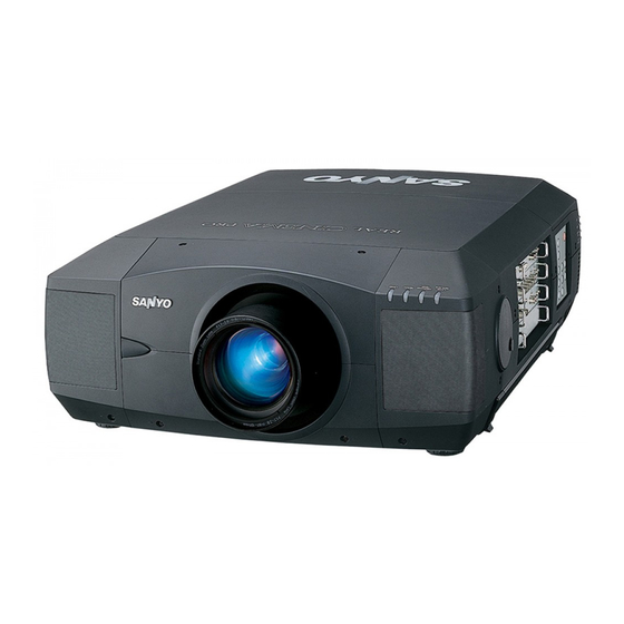
- Page 1 Multimedia Projector PLV-HD2000N/E MODEL ✽ Projection lens is optional. Owner's Manual...
-
Page 2: To The Owner
This symbol mark and recycle system are applied only to EU countries and not applied to the countries in the other area of the world. Your SANYO product is designed and manufactured with high quality materials and components which can be recycled and reused. -
Page 3: Safety Instructions
SAFETY INSTRUCTIONS All the safety and operating instructions should be read before the product is operated. Read all of the instructions given here and retain them for later use. Unplug this projector from AC power supply before cleaning. Do not use liquid or aerosol cleaners. Use a damp cloth for cleaning. -
Page 4: Federal Communication Commission Notice
Federal Communication Commission Notice This equipment has been tested and found to comply with the limits for a Class A digital device, pursuant to Part 15 of FCC Rules. These limits are designed to provide reasonable protection against harmful interference when the equipment is operated in a commercial environment. -
Page 5: Table Of Contents
TABLE OF CONTENTS FEATURES AND DESIGN PREPARATION NAME OF EACH PART OF PROJECTOR SETTING-UP PROJECTOR CONNECTING AC POWER CORD LENS INSTALLATION POSITIONING PROJECTOR LENS SHIFT ADJUSTMENT PICTURE LEVEL AND TILT ADJUSTMENT INSTALLING PROJECTOR IN PROPER POSITION MOVING PROJECTOR CONNECTING PROJECTOR TERMINALS OF PROJECTOR CONNECTING TO COMPUTER CONNECTING TO VIDEO EQUIPMENT... -
Page 6: Features And Design
This Multimedia Projector is designed with most advanced technology for portability, durability, and ease of use. This projector utilizes built-in multimedia features, a palette of 68.72 billion colors, and matrix liquid crystal display (LCD) technology. Compatibility This projector widely accepts various video and computer input signals including;... -
Page 7: Preparation
PREPARATION NAME OF EACH PART OF PROJECTOR FRONT OF CABINET INFRARED REMOTE RECEIVER PROJECTION LENS LENS CAP CAUTION Do not turn on a projector with lens cap attached. High temperature from light beam may damage lens cap and result in fire hazard. BACK OF CABINET EXHAUST VENT HOT AIR EXHAUSTED ! -
Page 8: Setting-Up Projector
PREPARATION This projector uses nominal input voltages of 120 V or 200-240 V AC. This projector automatically selects correct input voltage. It is designed to work with single- phase power systems having a grounded neutral conductor. To reduce risk of electrical shock, do not plug into any other type of power system. -
Page 9: Lens Installation
Before setting up a projector, install Projection Lens on a Projector. 1. Before installation, check where a projector is used and prepare suitable lens. For specifications of Projection Lens, refer to manual separately attached or contact sales dealer where you purchased a projector. 2. -
Page 10: Picture Level And Tilt Adjustment
PREPARATION PICTURE LEVEL AND TILT ADJUSTMENT Picture tilt and projection angle can be adjusted with handles on both sides of a projector. Projection angle can be adjusted to 5.7 degrees upper way. Press knob on handle. Handle pop out. Turn handles (right and left) until picture is projected on proper position. -
Page 11: Moving Projector
For safety, be sure to hold Carrying Handles on both sides by 2 or more people when moving a projector. Moving it unproperly may result in damage of cabinet or person's injury. Replace lens cap and retract feet to prevent damage to lens and cabinet. -
Page 12: Connecting Projector
CONNECTING PROJECTOR TERMINALS OF PROJECTOR This projector applies various input/output terminals and 4 terminal slots for expansion to tune to diversity of signals from computers and video equipment. 4-built-in Terminal Slots enable you to arrange desired combinations of input sources just by changing Terminal Boards. - Page 13 INPUT/OUTPUT TERMINALS AND JACKS INPUT 1 DUAL LINK SDI INPUT JACKS Connect Dual link SDI output from video equipment to these jacks. (Refer to P16.) SERIAL PORT IN LINK A SERIAL PORT OUT R/Pr R/C JACK AUDIO OUT RESET (MONO) INPUT 2 5 BNC INPUT JACKS Connect component video output (Cr, Y,...
- Page 14 CONNECTING PROJECTOR SERIAL PORT IN TERMINAL If you control a projector by computer, you must connect a cable (not supplied) from your computer to this terminal. SERIAL PORT OUT TERMINAL This terminal outputs signal from SERIAL PORT IN. More than two projectors can be controlled with one computer by connecting SERIAL PORT IN.
-
Page 15: Connecting To Computer
CONNECTING TO COMPUTER Cables used for connection ✽ = Cables are not supplied with this projector.) • DVI Cable ✽ • DVI-VGA Cable (HDB 15 pin) ✽ ✽ • BNC Cable (BNC x 5) • Audio Cables (RCA x 2) ✽... -
Page 16: Connecting To Video Equipment
CONNECTING PROJECTOR CONNECTING TO VIDEO EQUIPMENT Cables used for connection ✽ • Video Cable (BNC) • Audio Cable (RCA x 2) ✽ • Scart Cable ✽ ✽ • DVI-VGA Adapter ✽ = Cables are not supplied with this projector.) Video Source (example) Video Equipment with Digital video signal output SDI Output... -
Page 17: Before Operation
BEFORE OPERATION SIDE CONTROLS AND INDICATORS FRONT INDICATORS ZOOM buttons Adjust zoom. (P24) Adjust focus. (P24) MENU button Open or close the On-Screen Menu operation. (P21, 22) SELECT button Executes the item selected. (P21) AUTO PC ADJ. button Operates the AUTO PC adjustment function. - Page 18 BEFORE OPERATION FRONT INDICATORS LAMP REPLACE indicator This LAMP REPLACE indicator lights yellow when any of Projection Lamps is nearing its end, and flashes when any of them becomes out. Check which lamp needs to be replaced on Lamp Status Display. (P43-44, 48) INDICATORS LAMP...
-
Page 19: Operation Of Remote Control
OPERATION OF REMOTE CONTROL ON-OFF ▲ ZOOM ▲ ▲ FOCUS ▲ SELECT RESET SELECT button Executes the item selected. (P21) SIGNAL EMISSION indicator This indicator lights red while a signal is being sent from the remote control to the projector. SCREEN button Selects image screen. -
Page 20: Remote Control Code Change And Operating Range
BEFORE OPERATION REMOTE CONTROL CODE CHANGE AND OPERATING RANGE Code Change This projector has eight different remote control codes (Code 1-Code 8); the factory-set, initial code (Code 1) and the other seven codes (Code 2 to Code 8). This switching function prevents remote control interference when operating several projectors or video equipment at the same time. -
Page 21: Operating On-Screen Menu
OPERATING ON-SCREEN MENU HOW TO OPERATE ON-SCREEN MENU You can control and adjust this projector through ON-SCREEN MENU. Refer to following pages to operate each adjustment on ON-SCREEN MENU. 1 DISPLAY MENU Press MENU button to display ON-SCREEN MENU. 2 MOVING POINTER Move pointer ( ✽... -
Page 22: Menu Bar
BEFORE OPERATION GUIDE WINDOW Shows selected Used to select computer item of ON- system or video system. SCREEN MENU. Shows selected system on this box. (Refer to P27-28) INPUT MENU Used to select input source (Input 1, Input 2, Input 3 or Input 4). Refer to P25. -
Page 23: Basic Operation
BASIC OPERATION TURNING ON / OFF PROJECTOR Complete peripheral connections (with Computer, VCR, etc.) before turning on projector. (Refer to "CONNECTING TO PROJECTOR" on Pages 13~16 for connecting that equipment.) Connect a projector's AC Power Cord into a wall outlet and turn MAIN ON/OFF SWITCH to ON. -
Page 24: Adjusting Screen
BASIC OPERATION Press ZOOM L/M button on Side Control or on Remote Control Unit. Message “Zoom” is displayed. Press ZOOM L button to make image larger, and press ZOOM M button to make image smaller. Press FOCUS L/M button on Side Control or on Remote Control Unit. -
Page 25: Selecting Input Source
SELECTING INPUT SOURCE DIRECT OPERATION Select INPUT source by pressing INPUT 1/2 and INPUT 3/4 buttons on Side Control or INPUT 1, INPUT 2, INPUT 3 and INPUT 4 on Remote Control Unit. MENU OPERATION Press MENU button and ON-SCREEN MENU will appear. Press POINT LEFT/RIGHT buttons to select Input and press SELECT button. - Page 26 BASIC OPERATION WHEN SELECT INPUT 2 (5 BNC TERMINAL) Move a pointer to source that you want to select and press SELECT button. When connect a computer output [5 BNC Type (Red, Green, Blue, Horiz. Sync and Vert. Sync.)] from a computer to R/Pr, G/Y, B/Pb, H/HV and V jacks.
-
Page 27: System Select
AUTOMATIC MULTI-SCAN SYSTEM This projector automatically tunes to most different types of computers based on XGA, SXGA, SXGA+, WXGA or UXGA (refer to “COMPATIBLE COMPUTER SPECIFICATIONS” on page 53). When a computer is selected, this projector automatically tunes to incoming signal and projects the proper image without any special setting. (Some computers need to be set manually.) The projector displays one of the Auto, -----, Mode 1 ~ Mode 20, or the system provided in the projector. -
Page 28: Select Video System
BASIC OPERATION Press MENU button and ON-SCREEN MENU will appear. Press POINT LEFT/RIGHT buttons to move a red frame pointer to SYSTEM SELECT Menu icon. Press POINT DOWN button to move a red arrow pointer to system that you want to select and then press SELECT button. SDI Input Projector automatically detects incoming SDI signal {(480i, 575i, 480p, 575p, 720p, 1035i, 1080i/60, 1080i/50, 1080p/60, 1080p/50, 1080p/30,... -
Page 29: Display Adjust
DISPLAY ADJUST This projector has a picture screen resize function, which enables you to display desirable image size. Press MENU button and ON-SCREEN MENU will appear. Press POINT LEFT/RIGHT button(s) to move a red frame pointer to DISPLAY ADJUST Menu icon. Press POINT UP/DOWN button and move a red frame pointer to Screen and then press SELECT button twice. -
Page 30: Auto Pc Adjustment
DISPLAY ADJUST Auto PC Adjustment function is provided to automatically adjust Fine sync, Total dots and Picture Position to conform to your computer. Auto PC Adjustment function can be operated as follows. Auto PC Adj. Press MENU button and ON-SCREEN MENU will appear. Press POINT LEFT/RIGHT button to move a red frame pointer to DISPLAY ADJUST Menu icon. -
Page 31: Manual Display Adjustments
MANUAL DISPLAY ADJUSTMENTS This projector can automatically tune to display signals from most computers and video equipments currently distributed. However, some computers and video equipments employ special signal formats which are different from standard ones and may not be tuned by Multi-Scan system of this projector. If this happens, projector cannot reproduce a proper image and image may be recognized as a flickering picture, a non-synchronized picture, a non-centered picture or a skewed picture. - Page 32 DISPLAY ADJUST Current mode Press SELECT button to show information of computer selected. Clamp Adjusts clamp position. When image has a dark bar(s), try this adjustment. Store To store adjustment parameters, move a red frame pointer to Store icon and then press SELECT button. Move a red arrow pointer to any of Mode 1 to 20 that you want to store and then press SELECT button.
-
Page 33: Image Adjustments
IMAGE ADJUSTMENTS IMAGE LEVEL SELECT (DIRECT) Select image level among Standard (AV), Cinema, Standard (PC), Real and Image 1 ~ Image 10 by pressing IMAGE button on Side Control or on Remote Control Unit. Select image level Image 1 ~ Image 10 by pressing IMAGE 1 ~ IMAGE 10 buttons on Remote Control Unit. -
Page 34: Image Level Adjustments
DISPLAY ADJUST Press MENU button and ON-SCREEN MENU will appear. Press POINT LEFT/RIGHT buttons to move a red frame pointer to IMAGE ADJUST Menu icon. Press POINT UP/DOWN button to move a red frame pointer to item that you want to adjust and then press SELECT button. Level of each item is displayed. - Page 35 Noise reduction Press POINT LEFT/RIGHT button(s) to change noise reduction mode. Dialog box display is changed to “Off”, “L1”, “L2” or “L3” to reduce noise (rough parts) of image. Off ······· Noise reduction OFF position. L1 ········ Noise reduction LEVEL 1 position. L2 ········...
- Page 36 DISPLAY ADJUST To move the red frame pointer to "MENU", and then press the SELECT button. The message "OK"? is displayed. Move the pointer to [Yes] and then press SELECT button. The COLOR MANAGEMENT menu will be exited and the display will return to the IMAGE ADJUST menu.
- Page 37 Gamma balance The Gamma balance function can be used to adjust the R, G, B Gamma balance of the screen. Press the POINT UP/DOWN button to move the red frame point- er to "Gamma balance", and then press the SELECT button. The Gamma balance adjust menu will appear.
-
Page 38: Setting
SETTING Press MENU button and ON-SCREEN MENU will appear. Press POINT LEFT/RIGHT button(s) to move a red-frame pointer to SETTING icon. Press POINT DOWN button to move a red-frame pointer to item that you want to set and then press SELECT button. Setting dialog box appears. - Page 39 Menu position This function is used to adjust the on-screen menu display position. When a SELECT button is pressed, the adjustment screen is displayed (arrows appear). Use the POINT UP/DOWN/LEFT/RIGHT button(s) to adjust the position. After making the adjustment, press a SELECT button to return to the Menu screen.
- Page 40 SETTING Power management This projector is equipped with a power management function. When the input signal is interrupted and any button is not pressed for 30 seconds or more, the power management function operates in order to reduce power consumption and conserve lamp operating time.
- Page 41 Key lock This function locks the operation of the projector's control panel and the remote control. This locks operation of the projector's control panel. This locks operation of the remote control. This cancels the Key lock function. If the projector's control panel accidentally becomes locked and you do not have the remote control nearby, turn the MAIN ON/OFF switch to OFF.
-
Page 42: Appendix
APPENDIX The Warning Temp. Indicator flashes red to let you know the internal temperature of the projector exceeds the normal level. If the temperature goes up further, the projector will be turned off automatically and the Ready indicator will go out. (The Warning Temp. -
Page 43: Lamp Management
This Projector is equipped with 4 Projection Lamps to ensure brighter image and those lamps are controlled by Lamp Management Function. Lamp Management Function detects status of all lamps and shows status on screen or on LAMP REPLACE indicator. This function also automatically controls Lamp Mode when any of lamps is out for end of life or malfunctions. -
Page 44: Lamp Replacement
APPENDIX When the life of the Projection Lamp of this projector draws to an end, the LAMP REPLACE indicator lights yellow. If this indicator lights yellow, replace the projection lamp with a new one promptly. WARNING: TURN OFF THE UV LAMP BEFORE OPENING THE LAMP COVER. -
Page 45: Cleaning Projection Lens
ORDER REPLACEMENT LAMP Replacement Lamp can be ordered through your dealer. When ordering a Projection Lamp, give the following information to the dealer. Model No. of your projector Replacement Lamp Type No. LAMP HANDLING PRECAUTIONS This projector uses a high-pressure lamp which must be handled carefully and properly. Improper handling may result in accidents, injury, or create a fire hazard. -
Page 46: Troubleshooting
APPENDIX Before calling your dealer or service center for assistance, check matters below once again. 1. Make sure you have connected a projector to your computer or video equipment as described in section "CONNECTING PROJECTOR" on pages 13 ~ 16. 2. - Page 47 You can often correct operating problems yourself. If a projector fails to work properly, see "TROUBLESHOOT- ING" section on page 46. To correct failure, try "Solutions". If after following all operating instructions, you find that service is necessary, contact Sanyo Service Station or store where you purchased unit.
-
Page 48: Indicators And Projector Condition
APPENDIX INDICATORS AND PROJECTOR CONDITION Check the Indicators for projector condition. Indicators LAMP WARNING READY REPLACE TEMP. yellow ※ ※ ※ ※ ※ ※ ※ • • • on : red • • • flashing : red Projector Condition LAMP green The projector is OFF. -
Page 49: Menu Tree
Input Input 1 LINK-A (YCbCr) LINK-B (YCbCr) Dual (YCbCr1) Dual (YCbCr2) Dual (YCbCr3) Dual (YCbCr4) Dual (RGB1) Dual (RGB2) Input 2 Input 3 RGB (Analog) RGB (Scart) RGB (PC digital) RGB (AV HDCP) XGA 1 System XGA 1 XGA 2 XGA 3 Custom System... - Page 50 APPENDIX Image adjust Image Contrast Brightness Color Tint Color temp. Green Blue Sharpness Gamma Noise reduction Progressive Auto picture control Auto lamp control Color management Gamma balance Reset Store Quit Setting Standard (AV) Cinema Standard (PC) Real Image 1 ~ Image 10 Quit 0 - 63 0 - 63...
-
Page 51: Technical Specifications
TECHNICAL SPECIFICATIONS Projector Type Dimensions (W x H x D) Net Weight LCD Panel System Panel Resolution Number of Pixels Color System Component Signal Motorized Lens Shift Scanning Frequency Projection Lamp Input 1 Jacks Input 2 Jacks Input 3 Jacks Other Jacks Remote Control Transmitter Feet Adjustment... -
Page 52: Configurations Of Terminals
APPENDIX DVI-I TERMINAL (DIGITAL/ANALOG) This terminal accepts only Digital (TMDS) or Analog (RGB) output signal. Connect display output terminal of computer to this terminal with DVI cable (supplied). Pin Configuration C1 C2 SERIAL PORT IN/OUT TERMINAL Pin Configuration Connect serial port output terminal of computer to this terminal with Serial Cable (not supplied). USB PORT TERMINAL Pin Configuration Connect USB port output terminal of computer or peripheral equipment to this terminal with USB port Cable (not supplied). -
Page 53: Compatible Computer Specifications
COMPATIBLE COMPUTER SPECIFICATIONS Basically this projector can accept a signal from all computers with V, H-Frequency mentioned below and less than 230 MHz of Dot Clock. ON-SCREEN H-Freq. RESOLUTION DISPLAY 640 x 480 480i 15.734 (Interlace) 768 x 576 575i 15.625 (Interlace) 640 x 480... -
Page 54: Optional Parts
APPENDIX When a input signal is digital from DVI terminal, refer to chart below. ON-SCREEN RESOLUTION DISPLAY D-VGA 640 x 480 720 x 480 D-480p Progressive 768 x 575 D-575p Progressive D-SVGA 800 x 600 D-XGA 1024 x 768 D-WXGA1 1366 x 768 D-WXGA2 1360 x 768... -
Page 55: Dimensions
APPENDIX DIMENSIONS Unit : inch (mm) 22.87 (581.0) 10.15 (258.0) 9.90 (251.5) 5.18 (131.5) 17.56 (446.0) 17.56 (446.0) 7.01 (178.0) 7.01 (178.0) 9.90 (251.5) 22.87 (581.0) 2.36 (60.0) 4.23 (107.5) 3.26 (82.8) 6.81 (173.0) 1.38 (35.0) 1.57 (40.0) 8.27 (210.0) 8.27 (210.0) Screw Holes for Ceiling Mount Screws: 9-M8... -
Page 56: Lcd Projector
LCD PROJECTOR LENS REPLACEMENT AND INSTALLATION PROCEDURES When installing or replacing the Projection Lens, refer to this manual. For installa- tion of the lens, use the parts designated in the manual. Do not use the installation manual and Light-Block Sheets in the lens package. Check the following parts supplied to this projector. - Page 57 LENS REPLACEMENT AND INSTALLATION PROCEDURE NOTE : The installation procedure and needed parts for lens installation depend on the type of the Projection Lens. Check the Model No. of the Projection Lens and be sure to install or replace the lens following procedure below.
- Page 58 Remove Lens Cap on the rear (mounting side) of Projection Lens and mount Lens on the lens Attachment with 4 Screws. (Use screws attached on lens.) Connect the Lens Motor Lead connector to the socket on the right-top of the lens attachment. (Motor Driven Lens only.) See Fig.
- Page 59 This projector has 6 Light-Block Sheets. Use 2 Light-Block Sheets corresponding with lens. (Refer to the list below.) Use 1 Light-block Sheet for MODEL LNS-W03 Set 2 Light-Block Sheets through the lens. Make sure the shape of the Light-Block Sheets are correct and be sure to set them as shown in the Fig. 8. NOTE: Be sure to set each Light-Block Sheet as shown in Fig-8.
- Page 60 Adjust focus of the Projection Lens. (LNS-W01, LNS-W01Z, LNS-T01, LNS-T01Z and LNS-W03 only.) Set up the projector and project image on the screen. Loosen Focus Lens Lock Screw and rotate Projection Lens to obtain proper focus. After adjusting focus, be sure to lock Projection Lens with Focus Lens Lock Screw securely.
- Page 61 FOCUS ADJUSTMENT (For Model LNS-W03) Set up the projector and project image on the screen. 1. Loosen the Focus Lock Screw on the projection lens. 2. Rotate the projection lens to obtain proper focus on center area of the screen. When the distance of the screen and lens is 1 meter, mark (yellow) of the lens on Focus Lock Screw position.
-
Page 62: Correcting The Focus
When the lens is attached to the projector and images are being projected onto the screen, the peripheral focus may be out of focus in some localized areas. If this happens, insert the accessory in between the lens attachment and the lens to correct the focus. Inserting the spacers corrects the distance for best diagonal focus at the screen. - Page 63 - 8 -...
- Page 64 Printed in Japan Part No. 610 327 3082 (1AA6P1P5055-- MA4A) SANYO Electric Co., Ltd...