
Related Manuals for Taxitronic TX30


Summary of Contents for Taxitronic TX30
- Page 1 INTERFACOM, S.A. 22/12/2016 INSTALLATION MANUAL TAXIMETER TAXITRONIC TX30 I3000100.DOC 26.02.96...
-
Page 2: Maintenance
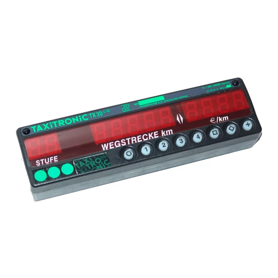
INTERFACOM, S.A. GENERAL INDEX 1. ASSEMBLY 2. ELECTRICAL INSTALLATION 3. SEALING 4. MAINTENANCE 5. TECHNICAL CHARACTERISTICS 6. IMPULSE GENERATOR 7. ADAPTER FOR ELECTRONIC PANNEL I3000100.DOC... - Page 3 INTERFACOM, S.A. 1. ASSEMBLY (Drawing 1) The mechanical installation of the TX30 taximeter is very simple due to its small size 180 x 50 x 32 mm. It can be built in and also assembled directly on the panel or on any type of bracket.
- Page 4 INTERFACOM, S.A. 2. ELECTRICAL INSTALLATION (Drawings 2,3,4 and 5) The electrical installation of the TX30 taximeter is similar to the one for the previous models. To reach the connectors, you only have to remove the CONNECTOR COVER ( First it is necessary to take out the central screw of the three screws that are on the front of the TX30).
- Page 5 INTERFACOM, S.A. Drawing 3 gives an example of the simplified installation of a taximeter controlling only an external light “FREE” or ”TAXI”. It also shows the possibility in the case of a radio-taxi company to use the light connector L6 to inform the central of the state of the taximeter.
- Page 6 O pushbutton in the taximeter. Calculate the constant K by doing a trial run or introducing it directly. Adjustment of the calendar-clock if necessary. Tariff recording. To have more information, see “Operation Manual for the TX30 Tariff Charger”. I3000100.DOC...
- Page 7 3. SEALING (Drawing 6) 3.1.- SEALS OF THE TX30 The sealing of the taximeter TX30 is totally made on the left of the frontal part of the taximeter, preventing from reaching the screws that block the accesses. See details of the taximeter drawing below: Seal Nº1: corresponds to the sealing of the box of the taximeter.
- Page 8 INTERFACOM, S.A. - In Drawing 6 you can observe different sealing methods: - Drawing 6, example 1.- Plastic seals and/or stamped lead seals to seal the box (item1), the connector cover (item 2) and the tarif connector cover plate (item 3). - Drawing 6, example 2.- Cable seal to seal the box (item 1), and another to seal together connector cover and tarif connector cover plate (item2).
- Page 9 INTERFACOM, S.A. 4. MAINTENANCE (Drawing 7 and 8)) When the TX30 does not work, the box must be opened to substitute the defective CPU plate with an asistance plate To open the taximeter box, there are two possibilities: 4.1. opening with the hands 4.2.
-
Page 10: Technical Characteristics
Storage temperature for keeping the information - 40 to + 85º C Dimensions 180 x 50 x 32 Approximate weight 204 gr. "K” constant of the device from 400 until 80000 pulses per Km/ml. NOTE: For the TX30-S the maximum power for the external light is: 36 W. I3000100.DOC... - Page 11 INTERFACOM, S.A. 6. IMPULSE GENERATOR 6.1.- INTRODUCTION For the vehicles with mechanical speedometer, you have to use a pulse generator that is managed by the taximeter. The pulse generator is inserted in the cable of the speedometer and converts the mechanical movement of this cable in an electrical signal, which is amplified and filtered by the taximeter.
- Page 12 INTERFACOM, S.A. 6.3.- SEALING (Drawing 11) The pulse generator also has got different sealing possibilities. Three of these possibilities are showed in Drawing 11. 6.4.- TECHNICAL CHARACTERISTICS The main technical characteristics of the pulse generator are: sensor type: Hall effect cell Number of pulses / revolution: 4 with double impulses train Feeding voltage:...
-
Page 13: Installation
INTERFACOM, S.A. 7.- VEHICLES WITH ELECTRONICAL SPEEDOMETER 7.1.- INTRODUCTION In the case of the vehicles equiped with electronical speedometer, the taximeter can be connected to these sensors with a sealable adaptor, which ensures the fiability of the system. This equipment consists of one circuit which is inserted between the distance sensor of the car and its speedometer. - Page 14 INTERFACOM, S.A. Equipment installation is made as follows: Disconnect the cable which joins the vehicle sensor to the speedometer by the side of the sensor. Usually, it is placed in the gearbox. Put the rubber washer enclosed in the adapter circuit in this cable in order it remains well fixed.
-
Page 15: Jumpers Configuration
INTERFACOM, S.A. 7.3.- JUMPERS CONFIGURATION. The equipment is configurated with the jumpers in order it can be adapted to the different sensors which are in the vehicles. The adapters delivered from the factory are configurated in order to work correctly with a signal of the following characteristics: Level 0 <... - Page 16 INTERFACOM, S.A. SIG NA L MO DULED IN A MPLITUDE D I A G R A M 2 Some vehicles Renault use a coil in distance sensor and then need an oscillator to operate the coil correctly. To install the adapter in these cars you have to make the following: Make jumpers SW1-P1, SW1-P2, SW1-P4, SW1-P6, SW1-P8, SW2-P1 and SW2-P6.