Advertisement
Quick Links
IG21, IG21R and IG31R Hardware Installation
Guide
First Published:
07-16-2020
Last Updated: 01-07-2020
Organization
This guide includes the following sections:
Cautions and Warnings, page 2
Conventions, page 2
Before You Begin, page 3
page 9
Summary of relevant cautions or warnings to adhere to when installing and
using the product.
Details on style conventions used in the guide.
Provides a general overview of the IG21, IG21R and IG31R Gateways. It
also provides important site preparation and safety measures to follow
before installing the system.s
Provides a summary of the systems and part numbers.
Provides instructions on how to attach a DIN rail for horizontal and vertical
mounting.
Provides instructions on how to attach a mounting bracket to the IG21,
IG21R and IG31R for horizontal and vertical mounting.
Provides instructions on how to mount the router on drywall.
Cisco Systems, Inc.
www.cisco.com
1
Advertisement

Related Manuals for Cisco IG21-VZ-K9


Summary of Contents for Cisco IG21-VZ-K9
-
Page 1: Table Of Contents
Provides instructions on how to attach a mounting bracket to the IG21, Brackets, page 7 IG21R and IG31R for horizontal and vertical mounting. Mounting the Router on a Wall Using Two KeyHoles, Provides instructions on how to mount the router on drywall. page 9 Cisco Systems, Inc. www.cisco.com... -
Page 2: Cautions And Warnings
IG21, IG21R and IG31R Hardware Installation Guide Cautions and Warnings Front Panel and LED Definition, page 10 Provides an overview of key components on the front panel and LEDs. IG21R and IG31R Overview, page 13 Provides an overview of the feature set of the IG systems and LED definitions. -
Page 3: Before You Begin
The IG21 is a gateway that connects Smart Devices and Sensors to a Customer Network or Cloud applications. Table 1 IG21, IG21R and IG31R IoT Gateways IoT Gateway Interface Rugged IoT Gateway Carrier LTE + WiFi LTE+WiFi+CAN-bus + Ignition Verizon IG21-VZ-K9 IG21-VZ-B-K9 IG21R-VZ-K9 IG31R-VZ-B-K9 North America IG21-NA-K9 IG21-NA-B-K9 IG21R-NA-K9 IG31R-NA-B-K9... -
Page 4: Din Rail Mounting Instructions For Ig21, Ig21R And Ig31R
IG21, IG21R and IG31R Hardware Installation Guide DIN Rail Mounting Instructions for IG21, IG21R and IG31R DIN Rail Mounting Instructions for IG21, IG21R and IG31R The DIN Rail Mounting Kit supports either a horizontal or vertical mounting of the IG21. To attach the DIN Rail Bracket to the IG21, follow the steps noted below: Position the DIN Rail Bracket over the two mounting holes as shown in Figure 1. - Page 5 IG21, IG21R and IG31R Hardware Installation Guide DIN Rail Mounting Instructions for IG21, IG21R and IG31R You are now ready to attach the DIN rail bracket to support either a Vertical or Horizontal mounting of the IG21R or IG31R. Refer to the appropriate section noted below: ...
- Page 6 IG21, IG21R and IG31R Hardware Installation Guide DIN Rail Mounting Instructions for IG21, IG21R and IG31R Figure 3 Attaching the DIN Rail Bracket for Vertical Installation of IG21R or IG31R Attaching the DIN Rail Bracket to Support Horizontal Mounting After you attach the Adapter plate as detailed in the Attaching the Adapter Plate for IG21R and IG31R, page 4 section and shown in Figure...
-
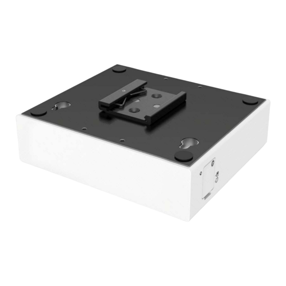
Page 7: Mounting The Router On A Wall Using Mounting Brackets
IG21, IG21R and IG31R Hardware Installation Guide Mounting the Router on a Wall Using Mounting Brackets Figure 4 Attach the DIN Rail Bracket for Horizontal Installations for IG21R or IG31R Mounting the Router on a Wall Using Mounting Brackets The IG21, IG21R or IG31R can be mounted on a wall using the two molded brackets and screws shipped with the router. These brackets are attached to the bottom of the router (Figure 5 Figure... - Page 8 IG21, IG21R and IG31R Hardware Installation Guide Mounting the Router on a Wall Using Mounting Brackets Figure 5 Wall Mounting Bracket for IG21 Using 4 Screws Figure 6 IIG Wall Mounting Bracket...
-
Page 9: Mounting The Router On A Wall Using Two Keyholes
IG21, IG21R and IG31R Hardware Installation Guide Mounting the Router on a Wall Using Two KeyHoles Mounting the Router on a Wall Using Two KeyHoles CAUTION: If you are mounting the router on drywall, use two hollow wall anchors to secure the unit to the wall using the two screws included in the kit. - Page 10 IG21, IG21R and IG31R Hardware Installation Guide Front Panel and LED Definition Figure 9 Place the Router of the Two Key Holes and the Mounting Front Panel and LED Definition Figure 10 IoT Gateway IG21 Front Panel...
- Page 11 IG21, IG21R and IG31R Hardware Installation Guide Front Panel and LED Definition Figure 11 IG21 Front and Side View with 12v and USB Connector Table 2 IG21 Front Panel Components (left to right) Item Description Indicates whether system is on or off. 12V= 12V connector for power input only Two Gigabit Ethernet ports: LAN (top port) and WAN port (bottom port)
- Page 12 IG21, IG21R and IG31R Hardware Installation Guide Front Panel and LED Definition Table 3 Feature Set for IG21 2 GPIO Ignition Power Management Operating Temperature 0C to 40C...
- Page 13 IG21, IG21R and IG31R Hardware Installation Guide IG21R and IG31R Overview Table 4 LED States on the IoT Gateway (IG21) <LED Assignment and Definitions Below May Change> LED No LED Name Description Status Customer Action LED 1 System Status Normal system operating status Green ------- RGA LED...
- Page 14 IG21, IG21R and IG31R Hardware Installation Guide IG21R and IG31R Overview Table 5 Feature Set for IG21R and IG31R in Figure 12 IP30 rating Yes (all PIDs) CAN bus IG31R only 2 GPIO One (1) on IG21R and Two (2) on IG31R Ignition Power Management Yes (IG31R) Operating temperature...
- Page 15 IG21, IG21R and IG31R Hardware Installation Guide IG21R and IG31R Overview Figure 13 Rugged IoT Gateway IG31R Table 7 Front and Side Panel (left to right) Front Panel Digital I/O connector 12/24V power input USB port 1 Gigabit Ethernet Port 1 WAN, 1 LAN Ethernet Port CAN bus Door panel (far right): Provides access to a reset...
- Page 16 IG21, IG21R and IG31R Hardware Installation Guide FCC and ISED Interference Statement FCC and ISED Interference Statement This equipment has been tested and found to comply with the limits for a Class A digital device, pursuant to part 15 of the FCC Rules. These limits are designed to provide reasonable protection against harmful interference when the equipment is operated in a commercial environment.
- Page 17 IG21, IG21R and IG31R Hardware Installation Guide FCC and ISED Interference Statement Table 8 Radio Transmitter Antenna type Model Number Antenna Gain (dBi) Dipole IG21 3.74 Dipole IG31R Le présent émetteur radio [IG21 IC: 2461N-IG21; IG31R IC: 2461N-IG31R] a été approuvé par Innovation, Sciences et Développement économique Canada pour fonctionner avec les types d'antenne énumérés ci-dessous et ayant un gain admissible maximal.
- Page 18 IG21, IG21R and IG31R Hardware Installation Guide FCC and ISED Interference Statement...