Table of Contents
Advertisement
Quick Links
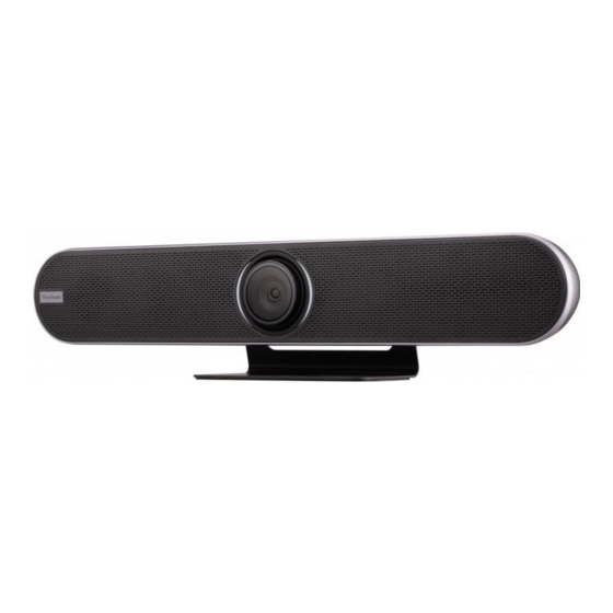
VB-CAM-201
User Guide
IMPORTANT: Please read this User Guide to obtain important information on installing and using your product in
a safe manner, as well as registering your product for future service. Warranty information contained in this User
Guide will describe your limited coverage from ViewSonic® Corporation, which is also found on our web site at
http://www.viewsonic.com in English, or in specific languages using the Regional selection box in the upper right
corner of our website.
Model No. VS18518
P/N: VB-CAM-201
Advertisement
Table of Contents

Related Manuals for ViewSonic VS18518


Summary of Contents for ViewSonic VS18518
- Page 1 Warranty information contained in this User Guide will describe your limited coverage from ViewSonic® Corporation, which is also found on our web site at http://www.viewsonic.com in English, or in specific languages using the Regional selection box in the upper right corner of our website.
- Page 2 As a world-leading provider of visual solutions, ViewSonic® is dedicated to exceeding the world’s expectations for technological evolution, innovation, and simplicity. At ViewSonic®, we believe that our products have the potential to make a positive impact in the world, and we are confident that the ViewSonic® product you have chosen will serve you well.
-
Page 3: Safety Precautions
Safety Precautions Please read the following Safety Precautions before you start using the device. • Keep this user guide in a safe place for later reference. • Read all warnings and follow all instructions. • To prevent damage, avoid any physical pressure, vibration, or immersion during transportation, possession, or installation of the product. -
Page 4: Table Of Contents
Contents Safety Precautions ............3 Introduction ..............6 Package Contents ....................6 Product Overview ....................7 VB-CAM-201 ......................7 I/O Ports ......................... 7 Remote Control ....................... 8 Initial Setup ............... 10 Installing the Camera ....................10 Making Connections ..........11 Connecting to Power ....................11 Connecting External Devices ................12 HDMI Connection .................... - Page 5 Appendix ..............34 Specifications ......................34 Camera ........................34 Audio ........................34 USB Features ......................34 Input/Output Interface ..................34 General ........................35 LED Indicators ......................36 LED Indicators - Host 1 and Host 2 Mode .............. 37 Troubleshooting ....................38 Maintenance......................39 General Precautions ....................
-
Page 6: Introduction
Introduction Package Contents VB-CAM-201 Conference Camera Quick Start Guide Package Contents VB-CAM-201 Conference Camera Quick Start Guide Package Contents Computer, TV, Mobile Phone, Speaker, Microphone, etc. Power Adapter (Supply) Power Cable (Supply) USB 3.0 Cable Wall anchor screw x 6 DC 12V IN Wall anchor screw x 6 DC 12V INUSB 3.0 Cable... -
Page 7: Product Overview
Product Overview VB-CAM-201 DC 12V USB 3.0 HDMI USB 2.0 I/O Ports DC 12V USB 3.0 HDMI USB 2.0 1. DC IN 2. USB 3.0 3. Reset Button 4. HDMI 5. USB 2.0 6. RJ45 NOTE: • The HDMI port only supports video output. •... -
Page 8: Remote Control
Remote Control Number Description Camera Disable Disable/Enable the video. Call Answer/Start call/Enter call interface1. Menu Control/Camera moving direction. Control Key Audio volume control. Volume Up/Down After pressing, the camera will exit the tracking mode. Exit Tracking Press for voice tracking of the speaker. Speaker Tracking Preset 1 Long press to set Preset 1;... - Page 9 Remote Control & Batteries • Avoid leaving the remote control or batteries in excessive heat or humidity. • Always dispose of old batteries in an environmentally friendly way. Contact your local government for more information on how to dispose of batteries safely. •...
-
Page 10: Initial Setup
Initial Setup Installing the Camera 1. Pre-drill six (6) holes into the wall. 2. Install the six (6) wall anchors. 3. Align the wall bracket with the six (6) anchors. 4. Install the wall bracket with the six (6) bracket screws. 5. -
Page 11: Making Connections
Making Connections Connecting to Power 1. Connect the power cord to the DC IN jack at the rear of the camera. 2. Connect the power cord plug to a power outlet. DC 12V USB 3.0 HDMI USB 2.0 NOTE: The power adapter includes four different plug faces. -
Page 12: Connecting External Devices
Connecting External Devices DC 12V USB 3.0 USB 2.0 HDMI HDMI Type-C NOTE: Ensure the camera (VB-CAM-201) is the default video and audio output device when being used. HDMI Connection Connect one end of an HDMI cable to the HDMI port of the camera. Then connect the other end of the cable to the HDMI port of your device. - Page 13 Host Mode Under host mode, VB-CAM-201 can automatically connect to VB-AUD-201 and has a connection capacity of two. If the connection is not reaching maximum capacity, VB-CAM-201 will continuously search for VB-AUD-201 until reaching maximum capacity. NOTE: If the connection time goes over 60 seconds, push the Bluetooth pairing button again on VB-AUD-201.
- Page 14 Client Mode Open the Bluetooth client mode and search for the device as an external speaker. If the connection is successful, the LED light will be blue.
-
Page 15: Remote Control Pairing
Remote Control Pairing 1. Connect the power supply to the camera and power it on. 2. Clear the paired status of the remote control: ͫ Press the Menu Button and OK buttons at the same time, keep pressing until the remote control indicator shows a steady red light, release the buttons to successfully clear the paired remote control. -
Page 16: Using The Device
Using the Device Configuring the Settings General Operations 1. Press the Menu button to display the On-Screen Display (OSD) Menu. MENU Setting Information Restore Default Exit 2. Use the Directional buttons to navigate the menu, and press OK to enter the selected menu. - Page 17 3. Return to the previous menu by selecting “Return” and pressing the OK button. INFORMATION Version 1.0.0 Model VB-CAM-201 Date 2021-12-31 192.168.000.22 Gateway 192.168.000.1 Netmask 355.355.355.0 MacAddress 9C:1F:32:8E:20:03 Return 4. To restore the menu settings to default, select “Restore Default” and press the OK button.
-
Page 18: On-Screen Display (Osd) Menu Tree
On-Screen Display (OSD) Menu Tree Main Menu Sub-menu Menu Option English 简体中文 Language 繁體中文 Français Auto 2D NR Close (-/+, 1~5) Auto 3D NR Close (-/+, 1~8) Luminance (-/+, 0~14) Contrast (-/+, 0~14) Setting Sharpness (-/+, 0~14) Saturation (-/+, 60~200) Video Setting Auto Indoor... - Page 19 Main Menu Sub-menu Menu Option Flip-H Flip Setting Flip-V Video Setting Return OSD Mirroring Return Setting 3A Enable Mic Equalizer Audio Setting Bluetooth Mode Bluetooth Setting BT Host Mode Return Return...
- Page 20 Main Menu Sub-menu Menu Option EPTZ 1.5x Zoom Limit¹ 4K@30 1080P30 HDMI Format¹ 1080P60 1080P50 Tracking Mode¹ Participants Speaker Smooth Tracking Effect² Setting Instantaneous Normal Tracking Speed² Slow Fast Version Model Date Information Gateway Netmask MacAddress Return Restore Default Return Exit ¹...
-
Page 21: Network
Network NOTE: The Camera IP address, by default, is set as Fixed IP address. Once you follow the below steps to connect to the camera, you can adjust the setting to Dynamic IP address and let your Router/DHCP server assign the network setting to the camera automatically. - Page 22 Connect to the Router Connect the camera and computer to the same router via a network cable. 1. Connect one end of a CAT5/5e/6 network cable to the camera. 2. Connect the other end of the network cable to the Ethernet interface of the router (LAN port).
-
Page 23: Setup Camera
Setup Camera Open your web browser and enter: http://192.168.100.88 You will see the login web page as below if your cables are connected and network settings are correct. There are two accounts built into the camera system: • Administrator - The default username is admin, password is test. This account can access all functions on the web page. -
Page 24: Preview Menu
Preview Menu There are three main functions in this menu: • Zoom adjust • Set and call presets • Pan, Tilt, and On-Screen Display (OSD) menu control Zoom Manually adjust the zoom of the camera. NOTE: The larger the number, the faster the in/out “zoom speed”. Preset Preset positions are the camera’s memorized Pan, Tilt, and Zoom position that can be recalled. - Page 25 Up/Down/Left/Right/Home Button These buttons can control the Pan and Tilt movement and the On-Screen Display (OSD) menu. To adjust the OSD menu: 1. If there is no OSD menu displayed on the screen, click the Menu button via mouse curser to open the OSD menu. 2.
-
Page 26: Video Menu
Video Menu Video Encode Encode level • Default: Mainprofile • Baseline: A simple profile with a low compression ratio. • Main: An intermediate profile with a medium compression ratio. • High: A complex profile with a high compression ratio. First Stream Encode protocol •... - Page 27 Frame rate • Default: 30 FPS • Select the number of images to be transmitted per second. I Key frame interval • Default: 30 • Select how often an I frame should be sent (H.264 only). The more often an I frame (full image) is sent, the better the video quality is;...
-
Page 28: Image Menu
Image Menu Brightness Brightness of the video image. Adjust these values to suit the ambient conditions. Saturation Saturation of the video image. Adjust these values to suit the ambient conditions. Contrast Contrast of the video image. Adjust these values to suit the ambient conditions. Sharpness Adjust these values to increase/decrease the clarity of detail in the video image. -
Page 29: Network Menu
Network Menu LAN Settings IP Configuration type • Dynamic IP address The IP address, subnet mask, and address for the default gateway are obtained automatically from a DHCP server. NOTE: • An activated DHCP server must be present in the network. •... - Page 30 IP address Manually insert the IP address, but make sure that IP address is not occupied by another device. Subnet mask Manually insert the subnet mask. Gateway Manually insert the gateway address (or known Router IP address). DNS address Manually insert the DNS server’s IP address. MAC address Display of the MAC address Port Settings...
-
Page 31: Settings Menu
Settings Menu Initialize Reboot Click the Reboot button to restart the camera. Factory Default Click the Apply button to set all settings back to default. - Page 32 User There are two accounts built into the camera system: • Administrator - The default username is admin, password is test. This account can access all functions on the web page. • Guest – The default username is guest, password is test. This account only can access the basic functions on the web page.
-
Page 33: Information Page
Information Page This page shows the below information: • Device ID • Software version • Device type • Webware version... -
Page 34: Appendix
Appendix Specifications Camera Item Specifications Video System 4K@30fps, 1080P@30fps, 720P@30fps Sensor Sony, 1/2.5 inch, CMOS, 8.51M pixel Lens 121° (DFOV), 110° (HFOV), 5x Digital Zoom, Pan/Tilt ± 15° MPT + EPTZ Digital Noise Reduction 2D & 3D Digital Noise Reduction Video S/N ≥... -
Page 35: General
General Item Specifications Control Method 2.4G Remote Control Installation Method Desktop, Wall, TV and other display devices. Operating Temperature 0° C ~ 40° C (32° F~104° F) Storage Temperature -40° C ~ 60° C (-40 ° F~140 ° F) 601 x 116 x 142 mm (bracket included) Dimensions (W x H x D) (23.67”... -
Page 36: Led Indicators
LED Indicators Light Description Amber Amber (Breathing) Blue (Chasing) Blue (Flashing) (breathing) Firmware upgrade Blue Blue (Steady, Breathing) Blue (Chasing) Blue (Flashing) (chasing) Waiting for Remote Control pairing Blue Blue (Steady, Breathing) White (Steady) Blue (Flashing) (flashing) Remote Control pairing finished Blue Blue (Steady, Breathing) White (Steady) -
Page 37: Led Indicators - Host 1 And Host 2 Mode
Light Description Solid Red Red (Steady) (steady) Microphone muted Solid Red Red (Steady) (steady) 3A function prohibited LED Indicators - Host 1 and Host 2 Mode Light Description Blue (Steady, Breathing) White (Steady) Purple (Steady) (Flashing) Blue Host 1 mode Blue (Steady, Breathing) White (Steady) Purple (Steady) -
Page 38: Troubleshooting
Troubleshooting Problem or Issue Possible Solutions • Make sure you have turned on the device by pressing the Power button on the remote control. • Make sure the power cord is properly and securely No power connected to the device and power outlet. •... -
Page 39: Maintenance
• ViewSonic® does not recommend the use of any ammonia or alcohol-based cleaners on the device or case. Some chemical cleaners have been reported to damage the device and/or case. • ViewSonic® will not be liable for damage resulting from use of any ammonia or alcohol-based cleaners. -
Page 40: Firmware Update
Firmware Update Visit the ViewSonic website or VB-CAM-201 web page to get latest firmware and upgrade VB-CAM-201. 1. Download the firmware upgrade tool (zip file) and the latest firmware version (pkg file). 2. Extract the upgrade tool file and open USB_Upgrade.exe. - Page 41 4. Once the connection is successful, the tool will show the message “Camera connected successfully”. 5. Choose PKG in Type before loading the firmware file.
- Page 42 6. Click on the “Load File” button to load the latest firmware file you downloaded from the ViewSonic website. NOTE: Do not rename the file name before the upgrade process. This may cause the upgrade to fail. 7. Click on the “Upgrade” button, then click on “OK”.
- Page 43 8. Wait for the upgrade to finish. 9. Once the update is finished, the SOC Version will show your latest firmware version.
- Page 44 10. If the tool doesn’t show your SOC version, you may click on “Version Search”. 11. If the tool cannot detect your camera, click on “Reconnect USB” or reconnect your USB cable again.
-
Page 45: Regulatory And Service Information
Regulatory and Service Information Compliance Information This section addresses all connected requirements and statements regarding regulations. Confirmed corresponding applications shall refer to nameplate labels and relevant markings on the unit. FCC Compliance Statement This device complies with part 15 of FCC Rules. Operation is subject to the following two conditions: (1) this device may not cause harmful interference, and (2) this device must accept any interference received, including interference that may cause undesired operation. -
Page 46: Fcc Radiation Exposure Statement
FCC Radiation Exposure Statement This equipment complies with FCC radiation exposure limits set forth for an uncontrolled environment. This equipment should be installed and operated with a minimum distance of 20 cm between the radiator & your body. Validity of using the module certification: In the event that these conditions cannot be met (for example certain laptop configurations or co-location with another transmitter), then the FCC authorization for this module in combination with the host equipment is no longer considered... -
Page 47: Ic Radiation Exposure Statement
IC Radiation Exposure Statement This equipment complied with IC RSS-102 radiation exposure limits set forth for an uncontrolled environment. This equipment should be installed and operated with minimum distance 20cm between the radiator & your body. The device for the band 5150-5825 MHz is only for indoor usage to reduce potential for harmful interference to co-channel mobile satellite systems. -
Page 48: Declaration Of Rohs2 Compliance
Declaration of RoHS2 Compliance This product has been designed and manufactured in compliance with Directive 2011/65/EU of the European Parliament and the Council on restriction of the use of certain hazardous substances in electrical and electronic equipment (RoHS2 Directive) and is deemed to comply with the maximum concentration values issued by the European Technical Adaptation Committee (TAC) as shown below: Proposed Maximum Actual... -
Page 49: Indian Restriction Of Hazardous Substances
Schedule 2 of the Rule. Product Disposal at End of Product Life ViewSonic® respects the environment and is committed to working and living green. Thank you for being part of Smarter, Greener Computing. Please visit the ViewSonic®... -
Page 50: Copyright Information
ENERGY STAR® is a registered trademark of the U.S. Environmental Protection Agency (EPA). As an ENERGY STAR® partner, ViewSonic® Corporation has determined that this product meets the ENERGY STAR® guidelines for energy efficiency. Disclaimer: ViewSonic® Corporation shall not be liable for technical or editorial errors or omissions contained herein;... -
Page 51: Customer Service
For technical support or product service, see the table below or contact your reseller. NOTE: You will need the product’s serial number. Country/ Region Website Country/ Region Website Asia Pacific & Africa Australia Bangladesh www.viewsonic.com/au/ www.viewsonic.com/bd/ 中国 (China) www.viewsonic.com.cn 香港 (繁體中文) www.viewsonic.com/hk/ Hong Kong (English) India www.viewsonic.com/hk-en/ www.viewsonic.com/in/... -
Page 52: Limited Warranty
How long the warranty is effective: ViewSonic® displays are warranted for between 1 and 3 years, depending on your country of purchase, for all parts including the light source and for all labor from the date of the first consumer purchase. - Page 53 (e) the serial number of the product. • Take or ship the product, freight prepaid, in the original container to an authorized ViewSonic® service center or ViewSonic®. • For additional information or the name of the nearest ViewSonic® service center, contact ViewSonic®. Limitation of implied warranties:...
- Page 54 Exclusion of damages: ViewSonic’s liability is limited to the cost of repair or replacement of the product. ViewSonic® shall not be liable for: • Damage to other property caused by any defects in the product, damages based upon inconvenience, loss of use of the product, loss of time, loss of...
-
Page 55: Mexico Limited Warranty
If a product proves to be defective in material or workmanship during the warranty period, ViewSonic® will, at its sole option, repair or replace the product with a like product. Replacement product or parts may include remanufactured or refurbished parts or components &... - Page 56 Exclusion of damages: ViewSonic®’s liability is limited to the cost of repair or replacement of the product. ViewSonic® shall not be liable for: • Damage to other property caused by any defects in the product, damages...
- Page 57 Name, address, of manufacturer and importers: México, Av. de la Palma #8 Piso 2 Despacho 203, Corporativo Interpalmas, Col. San Fernando Huixquilucan, Estado de México Tel: (55) 3605-1099 http://www.viewsonic.com/la/soporte/index.htm NÚMERO GRATIS DE ASISTENCIA TÉCNICA PARA TODO MÉXICO: 001.866.823.2004 Hermosillo: Villahermosa: Distribuciones y Servicios Computacionales SA de CV.
- Page 58 C0 M91 Y72 K24 Process Color C0 M0 Y0 K100 Process Color C0 M91 Y72 K24 Process Color Pantone Black C Spot Color Pantone 187 C Spot Color...