
Related Manuals for IBT Technologies IB500

Summary of Contents for IBT Technologies IB500
- Page 1 IB500 Half-Size Socket 7 CPU Card With Optional VGA/LAN/SCSI USER’S MANUAL Version 1.0A...
- Page 2 Intel and Pentium are registered trademarks of Intel Corporation. Microsoft Windows is a registered trademark of Microsoft Corporation. Winbond is a registered trademark of Winbond Electronics Corporation. All other product names or trademarks are properties of their respective owners. IB500 User’ s Manual...
-
Page 3: Table Of Contents
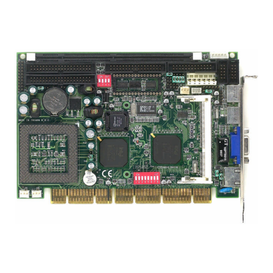
Board Dimensions.............4 Installations ..............5 Installing the CPU.............6 MicroPCI Daughter Card Installation ........6 Installing the Memory (DIMM) .........7 Setting the Jumpers............8 Connectors on IB500 ............17 Watchdog Timer Configuration........30 BIOS Setup..............31 VGA Drivers Installation ........55 LAN Drivers Installation.........58 SCSI Drivers Installation ........62 Appendix ..............68... - Page 4 A Picture of the IB500 CPU Card IB500 User’ s Manual...
-
Page 5: Introduction
INTRODUCTION Introduction Product Description IB500 is a high-performance PISA-compliant CPU card that comes with a MicroPCI Socket that supports MicroPCI daughter cards with VGA, VGA/LAN, LAN, and SCSI functions. It is based on the Intel 430TX PCIset and features a Socket 7 architecture that supports Socket 7 level processors with frequencies up to 400MHz using a front side bus of 60MHz or 66MHz. -
Page 6: Checklist
INTRODUCTION Checklist Your IB500 package should include the items listed below. • The IB500 CPU Card • This User’s Manual • 1 IDE Ribbon Cable • 1 Floppy Ribbon Connector • 2 Serial Port Ribbon Cables and 1 Parallel Port attached to a Mounting Bracket •... -
Page 7: Specifications
Monitors CPU/system temperature and voltages Monitoring SSD Interface Supports M-Systems 2MB~144MB DiskOnChip flash disk Other Features Watchdog timer Power 8A (max) +/-12V 200mA (max) Consumption Form Factor Half Size, PISA compliant Dimensions 186mm x 129mm (7.32” x 5.0”) IB500 User’ s Manual... -
Page 8: Board Dimensions
INTRODUCTION Board Dimensions IB500 User’ s Manual... -
Page 9: Installations
INSTALLATIONS Installations This section provides information on how to use the jumpers and connectors on the IB500 in order to set up a workable system. The topics covered are: Installing the CPU.............6 MicroPCI Daughter Card Installation ........6 Installing the Memory (DIMM) .........7 Setting the Jumpers............8... -
Page 10: Installing The Cpu
CPU overheating problem that would cause your system to hang or be unstable. MicroPCI Daughter Card Installation The IB500 CPU card is integrated with one MicroPCI socket that uses a 144-pin connector. The socket can accommodate the VGA, Ethernet or SCSI MicroPCI daughter cards. -
Page 11: Installing The Memory (Dimm)
INSTALLATIONS Installing the Memory (DIMM) The IB500 CPU Card supports one 168-pin DIMM socket that accommodates a maximum memory of 256MB in SDRAM type. The memory module capacities supported are 32MB, 64MB, 128MB and 256MB. Installing and Removing DIMMs To install the DIMM, locate the memory slot on the CPU card and perform the following steps: 1. -
Page 12: Setting The Jumpers
INSTALLATIONS Setting the Jumpers Jumpers on IB500 are used to select various settings and features according to your needs and applications. Contact your supplier if you have doubts about the best configuration for your needs. The following lists the connectors on IB500 and their respective functions. -
Page 13: Jumper Locations On Ib500
INSTALLATIONS Jumper Locations on IB500 DiskOnChip Socket IB500 User’ s Manual... -
Page 14: S2(1-4): Front Side Bus Selector
2.8V 1.95V OPEN CLOSE off off off on on off on on 2.2V 1.90V OPEN CLOSE off on off off off off on on 2.05V CLOSE on on on on IB500 User’ s Manual... - Page 15 Tillamook* 66MHz (233MHz) 3.5x off off off off off off off on Tillamook* 66MHz (266MHz) off off off off on off on off * Tillamook has a CPU Vcore voltage of 1.95V. IB500 User’ s Manual...
- Page 16 66MHz K6/2-333 off off off off off on on off 66MHz K6/2-366 5.5x off off off off off off on off 66MHz K6/2-400 off off off off on off off off IB500 User’ s Manual...
- Page 17 PR200 66MHz (166MHz) 2.5x off off off off on on off off PR233 66MHz (200MHz) off off off off off on off off PR266 66MHz (233MHz) 3.5x off off off off off off off off IB500 User’ s Manual...
-
Page 18: Jp1, Jp2, Jp3: Rs232/422/485 (Com2) Selection
This 4-pin connector allows the user to connect an external battery to maintain the information stored in the CMOS RAM in case the built-in battery malfunctions. Pin # Signal Name Ground Battery GND N.C. JP9: Watchdog Selection Setting Function Pin 1-2 Short/Closed Pin 2-3 Reset Short/Closed IB500 User’ s Manual... -
Page 19: Jp12: Clear Cmos Content
The IBD99/69 C&T 69000 VGA MicroPCI daughter card supports 5V and 3.3V power. Use JP2 to select the power setting. 3.3V Setting 5V Setting JP3: Onboard LAN Enable/Disable (IBD99) Setting LAN Function Pin 1-2 Enabled Short/Closed Pin 2-3 Disabled Short/Closed IB500 User’ s Manual... -
Page 20: Jp4: Onboard C&T Vga Enable/Disable (Ibd99)
JP4: Onboard C&T VGA Enable/Disable (IBD99) Setting VGA Function Pin 1-2 Enabled Short/Closed Pin 2-3 Disabled Short/Closed JP11: CPU VIO Voltage Selection JP11 Setting Voltage 2.5V, for Intel Pin 1-2 low-power Short/Closed consumption CPU Pin 2-3 3.3V (default) Short/Closed IB500 User’ s Manual... -
Page 21: Connectors On Ib500
INSTALLATIONS Connectors on IB500 The connectors on IB500 allows you to connect external devices such as keyboard, floppy disk drives, hard disk drives, printers, etc. The following table lists the connectors on IB500 and their respective functions. Connector Locations on IB500............18 J1: External Keyboard Connector............ -
Page 22: Connector Locations On Ib500
INSTALLATIONS Connector Locations on IB500 DiskOnChip Socket J2: System Function Connector J8: Secondary EIDE Connector J3: Primary EIDE Connector J4: Floppy Drive Connector JP7: Wake On LAN Connector JP6: External ATX Power Connector J10: USB Connector J5: Parallel Port Connector... -
Page 23: J1: External Keyboard Connector
Power LED and Keylock Speaker Speaker: Pins 1 - 4 This connector provides an interface to a speaker for audio tone generation. An 8-ohm speaker is recommended. Pin # Signal Name Speaker out No connect Ground IB500 User’ s Manual... - Page 24 Turbo LED Connector: Pins 8 and 18 There is no turbo/deturbo function on the CPU card. The Turbo LED on the control panel will always be On when attached to this connector. Pin # Signal Name Ground IB500 User’ s Manual...
-
Page 25: J3, J8: Eide Connectors
Host data 15 Ground DRQ0 Ground Host IOW Ground Host IOR Ground IOCHRDY Host ALE DACK0 Ground IRQ14 No connect Address 1 No connect Address 0 Address 2 Chip select 0 Chip select 1 Activity Ground IB500 User’ s Manual... -
Page 26: J4: Floppy Drive Connector
Drive select 1 Ground Drive select 0 Ground Motor enable 1 Ground Direction Ground Step Ground Write data Ground Write gate Ground Track 00 Ground Write protect Ground Read data Ground Side 1 select Ground Diskette change IB500 User’ s Manual... -
Page 27: Jp4: P8 At Power Connector
Ground PD6, parallel data 6 Ground PD7, parallel data 7 Ground ACK, acknowledge Ground Busy Ground Paper empty Ground Select JP6: External ATX Power Connector Pin # Signal Name 5VSB (Standby +5V) PS-ON (soft on/of) Ground IB500 User’ s Manual... -
Page 28: J6, J7: Com1, Com2 Serial Port
INSTALLATIONS J6, J7: COM1, COM2 Serial Port J6 and J7, both 10-pin headers, are the onboard serial port connectors of the IB500. The following table shows the pin assignments of these connectors. Pin # Signal Name DCD, Data carrier detect... -
Page 29: J10: Usb Connector
Mouse data N.C. Ground N.C. 5V Mouse Clock J12: PS/2 Keyboard Connector Pin # Signal Name Keyboard data N.C. Keyboard clock N.C. J13: PS/2 Mouse Connector Pin # Signal Name Mouse data N.C. N.C. Mouse Clock N.C. IB500 User’ s Manual... -
Page 30: J14: Vga Crt Connector
J16 is a 3-pin header for the CPU fan. The fan must be a 12V fan. Pin # Signal Name Rotation +12V Ground J17: System Fan Power Connector J17 is a 3-pin header for the system fan. The fan must be a 12V fan. Pin # Signal Name Rotation +12V Ground IB500 User’ s Manual... -
Page 31: J1: Lcd Panel Connector (Ibd69)
The IBD69 C&T 69000 VGA MicroPCI daughter card supports LCD panels. Use J1 to connect the system to an LCD panel. Signal Name Pin # Pin # Signal Name 5V or 3.3V 5V or 3.3V SHFCLK ENABKL FPVDD FLM(V SYNC) FPVEE LP(H SYNC) +12V +12V IB500 User’ s Manual... -
Page 32: Flat Panel Display Interface Pin Descriptions
WakeOnLAN connector. The following table shows the pin out assignments of this connector. WakeOnLAN will function properly only with an ATX power supply with 5VSB that has 800mA. Pin # Signal Name +5VSB Ground Wake on LAN IB500 User’ s Manual... -
Page 33: J1: Ultra2 Scsi Connector (Ibd60)
GROUND LVTRMPWR LVTRMPWR LVTRMPWR LVTRMPWR N.C. GROUND GROUND LVATNP LVATNM GROUND GROUND LVBSYP LVBSYM LVACKP LVACKM LVRSTP LVRSTM LVMSGP LVMSGM LVSELP LVSELM LVCDP LVCDM LVREQP LVREQM LVIOP LVIOM LVDP8 LVDM8 LVDP9 LVDM9 LVDP10 LVDM10 LVDP11 LVDM11 IB500 User’ s Manual... -
Page 34: Watchdog Timer Configuration
The following describes how the timer should be programmed. Enabling Watchdog: AX, 000FH (Choose the values from 0) DX, 0443H DX, AX Disabling Watchdog AX, 00FH (Any value is fine.) DX, 0441H DX, AX WATCHDOG TIMER CONTROL TABLE Level Value Time/sec Level Value Time/sec IB500 User’ s Manual... -
Page 35: Bios Setup
PNP/PCI Configuration..............47 Load BIOS Defaults ................. 49 Load Setup Defaults ................. 49 Integrated Peripherals ............... 50 Supervisor / User Password............. 52 IDE HDD Auto Detection..............53 HDD Low Level Format ..............53 Save & Exit Setup................54 IB500 User’ s Manual... -
Page 36: Bios Introduction
<PgUp> and <PgDn> keys to change entries, <F1> for help and <Esc> to quit. When you enter the Setup utility, the Main Menu screen will appear on the screen. The Main Menu allows you to select from various setup functions and exit choices. IB500 User’ s Manual... -
Page 37: Standard Cmos Setup
You will need to run the Standard CMOS option, however, if you change your system hardware configurations, the onboard battery fails, or the configuration stored in the CMOS memory was lost or damaged. IB500 User’ s Manual... - Page 38 Hour : 00 to 23 Minute : 00 to 59 Second : 00 to 59 To set the time, highlight the “Time” field and use the <PgUp>/ <PgDn> or +/- keys to set the current time. IB500 User’ s Manual...
- Page 39 The hard disk will not work properly if you enter incorrect information in these fields. If your hard disk drive type is not matched or listed, you can use Type User to define your own drive type manually. IB500 User’ s Manual...
- Page 40 The system boot will not be halted for a disk error; it will stop for all other errors. All, But Disk/Key The system boot will not be halted for a keyboard or disk error; it will stop for all other errors. IB500 User’ s Manual...
-
Page 41: Bios Features Setup
If you will run such a program, disable the Virus Warning feature. CPU Internal Cache / External Cache These items allow you to enable (speed up memory access) or disable the cache function. By default, these items are Enabled. IB500 User’ s Manual... - Page 42 Typematic Rate Setting When disabled, continually holding down a key on your keyboard will generate only one instance. When enabled, you can set the two typematic controls listed next. By default, this field is set to Disabled. IB500 User’ s Manual...
- Page 43 RAM. Video Shadow will increase the video speed. C8000 - CBFFF Shadow/DC000 - DFFFF Shadow Shadowing a ROM reduces the memory available between 640KB to 1024KB. These fields determine whether optional ROM will be copied to RAM or not. IB500 User’ s Manual...
-
Page 44: Chipset Features Setup
DRAM Leadoff Timing Select the combination of CPU clocks the DRAM on the IB500 requires before each read from or write to the memory. Changing the value from the setting determined by the board designer for the installed DRAM may cause memory errors. - Page 45 HCLKs of 2/2 or 3/3. The system board designer should set the values in this field, depending on the DRAM installed. Do not change the values in this field unless you change specifications of the installed DRAM or the installed CPU. IB500 User’ s Manual...
- Page 46 16MB. By default, this field is set to Disabled. PCI 2.1 Compliance Concurrent PCI allows multiple PCI transfers from the PCI master buses to memory to CPU. By default, this field is set to Disabled. IB500 User’ s Manual...
- Page 47 System Hardware Monitoring Device. CPU and Chassis Fan Speed These fields show the RPM (revolution per minute) status of your CPU fan and Chassis fan. This is a function of the optional System Hardware Monitoring Device. IB500 User’ s Manual...
-
Page 48: Power Management Setup
This field allows you to use the Advanced Power Management device to enhance the Max. Power Saving mode and stop the CPU’s internal clock. If the Max. Power Saving is not enabled, this will be preset to NO. IB500 User’ s Manual... - Page 49 When the system enters Doze mode, the CPU clock runs only part of the time. You may select the percent of time that the clock runs. ZZ Active in Suspend When Enabled, the ZZ signal is active during Suspend mode. IB500 User’ s Manual...
- Page 50 IRQ 8, the system wakes up from suspend mode. Reload Global Timer Events This section determines the reloading of the ‘timers’ after entering the Full On mode. When enabled, the item reloads the set time of inactivity before entering the power saving mode. IB500 User’ s Manual...
-
Page 51: Pnp/Pci Configuration
However, this capability needs you to use a PnP operating system such as Windows 95. The default value is Manual. Reset Configuration Data This field allows you to determine whether to reset the configuration data or not. The default value is Disabled. IB500 User’ s Manual... - Page 52 ISA card in your system that require the use of this address range, you can increase the block size to either 8K, 16K, 32K or 64K. If you are using ICU to accomplish this task, leave “Used MEM base addr” to its default setting of N/A. IB500 User’ s Manual...
-
Page 53: Load Bios Defaults
á â à ß : Select Item ESC : Quit F10 : Save & Exit Setup (Shift) F2 : Change Color Load BIOS Defaults except Standard CMOS Setup To load SETUP defaults value to CMOS SRAM, enter “Y”. If not, enter “N”. IB500 User’ s Manual... -
Page 54: Integrated Peripherals
PIO (Programmed Input/Output) allows the BIOS to communicate with the controller and CPU directly. The system supports five modes, numbered from 0 (default) to 4, which primarily differ in timing. When Auto is selected, the BIOS will select the best available mode. IB500 User’ s Manual... - Page 55 This field determines the UART 2 mode in your computer. The default setting is Normal. Parallel Port Mode This field allows you to determine parallel port mode function. Standard Printer Port Enhanced Parallel Port Extended Capabilities Port ECP+EPP Extended Capabilities Port or Enhanced Parallel Port IB500 User’ s Manual...
-
Page 56: Supervisor / User Password
SAVE & EXIT SETUP LOAD SETUP DEFAULTS EXIT WITHOUT SAVING á â à ß : Select Item ESC : Quit F10 : Save & Exit Setup (Shift) F2 : Change Color Change / Set / Disable Password IB500 User’ s Manual... -
Page 57: Ide Hdd Auto Detection
This option should only be used by a professional. Low-level formatting can cause irreparable damage to your hard disk. The procedures include selecting the drive you want to low-level format, determining the bad tracks, and proceeding with pre-formatting. IB500 User’ s Manual... -
Page 58: Save & Exit Setup
SAVE & EXIT SETUP LOAD SETUP DEFAULTS EXIT WITHOUT SAVING á â à ß : Select Item ESC : Quit F10 : Save & Exit Setup (Shift) F2 : Change Color Abandon all Data & Exit Setup IB500 User’ s Manual... -
Page 59: Vga Drivers Installation
VGA Drivers Installation This section provides information on how to install the VGA drivers that come with IB500. Please follow the instructions set forth in this section carefully. Please note that there must be relevant software installed in your system before you could proceed to install the VGA drivers. - Page 60 Continue by choosing Close. You will be asked to restart your machine. Do so accordingly. 10. After the system has restarted, you can go back into the Display applet and select alternate screen resolutions and color depths. IB500 User’ s Manual...
- Page 61 Click on Yes to continue. Click on Apply to switch to the new graphics mode. Graphics modes are changed dynamically on NT 4.0, so you do not need to shut down and restart for the new screen settings to work. IB500 User’ s Manual...
-
Page 62: Lan Drivers Installation
The driver installation information in this manual is for reference only. It maybe possible that the installation procedure or the driver information has changed. In such cases, please contact the local agent or the distributor where you purchased the product. IB500 User’ s Manual... -
Page 63: Introduction
Creates a drivers disk for Windows 95 and Windows 98. MAKENT.BAT Creates a drivers disk for Windows NT. MAKEW2K.BAT Creates a drivers disk for Windows 2000. MAKENW.BAT Creates a drivers disk for Novell NetWare servers and clients. IB500 User’ s Manual... -
Page 64: Installing Lan Drivers For Windows 95
9. Enter the appropriate drive for your disk media (A:) and click OK. 10. Click OK at the Select Device dialog box. 11. The Update Wizard displays the message that it has found the driver. Click Next. 12. Click Finish. 13. Restart your computer when prompted. IB500 User’ s Manual... -
Page 65: Installing Lan Drivers For Windows Nt
Then follow the prompts to complete installation. When the adapter is added you'll see a new adapter listed in the Network adapters list. 6. Click Close to finish and configure any protocols as prompted. 7. Restart Windows NT when prompted. IB500 User’ s Manual... -
Page 66: Scsi Drivers Installation
The driver installation information in this manual is for reference only. It maybe possible that the installation procedure or the driver information has changed. In such cases, please contact the local agent or the distributor where you purchased the product. IB500 User’ s Manual... -
Page 67: Installing Scsi Driver For Dos
5. At the prompt, type in A:\win95, insert Initio INI-A100U2W driver disk 1, and click the OK button. 6. Select Initio INI-A100U2W Host Adapter, click the OK button. Windows 95 will copy INIA100.MPD to your hard disk. Reboot to complete the driver installation. IB500 User’ s Manual... - Page 68 2. Click the Driver tab, and then click the Change Driver tab. 3. Type A:\win95 and insert Initio INI-A100U2W driver disk into floppy drive A:, click OK, Windows 95 will copy the new device driver into the hard disk. IB500 User’ s Manual...
-
Page 69: Driver Installation For Windows-Nt
3. In the INSTALL DRIVER window, select HAVE DISK..4. In the INSTALL FROM DISK window that is displayed, enter the Initio Driver path name: - Insert INI-A1000U2W Driver Disk 1 into drive A: - Type A:\WINNT, then select OK IB500 User’ s Manual... - Page 70 "Setup is inspecting your computer's hardware configuration...", You have two seconds to press the F6 key to enter the driver installation screen. Insert the Initio Windows NT installation diskette, and type A:\WINNT to load the INI-A100U2W Windows NT driver. IB500 User’ s Manual...
-
Page 71: Installing Scsi Driver For Os/2 3.X & 4.X
PCI device address /DM:d,.. Enable direct access storage device (DASD) support on target d /!DM:d,.. Disable DASD manager support on target d /SM:d,.. Enable SCSI manager support on target d /!SM:d,.. Disable SCSI manager support on target d IB500 User’ s Manual... -
Page 72: Appendix
APPENDIX Appendix A. Post Codes B. I/O Port Address Map C. Interrupt Request Lines (IRQ) IB500 User’ s Manual... -
Page 73: Post Codes
Test F000h segment shadow to see whether it is R/W-able or not. If test fails, keep beeping the speaker. Auto detect flash type to load appropriate flash R/W codes into the run time area in F000 for ESCD & DMI support. IB500 User’ s Manual... - Page 74 2. Put information on screen display, including Award title, CPU type, CPU speed … . Reset keyboard except Winbond 977 series Super I/O chips. Test 8254 Test 8259 interrupt mask bits for channel 1. Test 8259 interrupt mask bits for channel 2. Test 8259 functionality. IB500 User’ s Manual...
- Page 75 (Optional Feature) Enter AWDFLASH.EXE if : -AWDFLASH is found in floppy drive. -ALT+F2 is pressed Detect & install all IDE devices: HDD, LS120, ZIP, CDROM… .. Detect serial ports & parallel ports. Detect & install co-processor IB500 User’ s Manual...
- Page 76 2. Update keyboard LED & typematic rate 1. Build MP table 2. Build & update ESCD 3. Set CMOS century to 20h or 19h 4. Load CMOS time into DOS timer tick 5. Build MSIRQ routing table. Boot attempt (INT 19h) IB500 User’ s Manual...
-
Page 77: I/O Port Address Map
Parallel Port #1(LPT1) 360 - 36F Network Ports 3B0 - 3BF Monochrome & Printer adapter 3C0 - 3CF EGA adapter 3D0 - 3DF CGA adapter 3F0h - 3F7h Floppy Disk Controller 3F8h - 3FFh Serial Port #1(COM1) IB500 User’ s Manual... -
Page 78: Interrupt Request Lines (Irq)
IRQ5 Parallel Port #2 IRQ6 Floppy Disk Controller IRQ7 Parallel Port #1 IRQ8 Real Time Clock IRQ9 Serial Port #3 IRQ10 Serial Port #4 IRQ11 Reserved IRQ12 Reserved IRQ13 80287 IRQ14 Primary IDE IRQ15 Secondary IDE IB500 User’ s Manual...