Table of Contents
Advertisement
Quick Links
Advertisement
Table of Contents

Related Manuals for Pioneer APPLI-PRO DASIC

Summary of Contents for Pioneer APPLI-PRO DASIC
- Page 1 Operations and Instruction Manual Revised November 2011...
-
Page 2: Table Of Contents
TABLE OF CONTENTS Topic Page TOOLS NEEDED for INSTALLATION and SERVICE………………………….. HARDWARE NEEDED for INSTALLATION…………………………………..…. ASSEMBLY of APPLICATOR………………………………………………….….. MOUNTING TANK ASSEMBLY to MACHINE or TRACTOR……………..…… ASSEMBLY of NOZZLE BAR……………………………………………………... INSTALLATION of NOZZLE BAR SMALL BALER…………………………………………………………….. LOADING WAGON………………………………………………………… CHOPPER…………………………………………………..………………. INSTALLATION of the CONTROL BOX…………………………………………. INSTALLATION of the CABLES………………………………………………….. -
Page 3: Tools Needed For Installation And Service
INTRODUCTION The Appli-Pro Basic Application System was built for Pioneer Hi-Bred International, Inc. by a leading agricultural manufacturer. The Basic is an integrated system, designed and calibrated specifically for Pioneer ® brand products. This unique system was developed to offer you the following advantages: ... -
Page 4: Assembly Of Applicator
ASSEMBLY OF APPLICATOR Step 1 Thread the intake assembly into side tank fitting, and make sure filter is pointed towards the front of the tank as well. Intake assembly on side of Attach free tank hose end to elbow Step 2 Locate free end of hose that is installed to the pump’s intake. - Page 5 Option B – Remote mounted gauge 1. Remove gauge tee from pump assembly and remove fitting (003-M1212) from tee. Remove this section Step 1 2. Thread straight fitting (003-A3812) into both the removed tee and the one still on the pump assembly.
-
Page 6: Mounting Tank Assembly To Machine Or Tractor
4. Drill holes and mount the gauge holder in a location that can be seen from the operator’s station. 5. Cut a length of hose (002-9003AS) that will reach from the pump discharge to the remote mounted gauge. Attach one end to the pump discharge and the other to the intake barb fitting on the gauge assembly. -
Page 7: Assembly Of Nozzle Bar
ASSEMBLY OF NOZZLE BAR The Appli-Pro Basic system comes with the ability to use one, two, or three nozzles at a time. Set up your nozzle bar as follows- 1. Loosen the screw on ½” Bar Clamp (004-1209). Do not fully remove screw. 2. -
Page 8: Installation Of Nozzle Bar
INSTALLATION OF NOZZLE BAR – BALER Recommendation: use 1-2 nozzles, depending on swath width. Determine a location to mount the nozzle pipe on the front hood and above the pickup head of the baler. Make sure not to interfere with any moving pieces of the baler. Note: Additional modification and fabrication maybe needed for your specific machine. -
Page 9: Installation Of The Control Box
INSTALLATION OF THE CONTROL BOX LOCATION of CONTROL BOX Locate the control where it can be easily reached from the tractor’s seat. WIRING Route the wire to the starter solenoid on all 12v tractors. Connect the green lead marked+ to the hot terminal on the starter. Connect the black lead to a good ground. DO NOT REVERSE THE LEADS. -
Page 10: Calibration Small Square Baler
CALIBRATION FOR SMALL SQUARE BALERS There are two steps that you need to know when calibrating your applicator: determining your ton/hour and using the correct tip(s) and PSI. Step 1 Bale for three minutes and count the number of bales made in those three minutes. Weigh several bales to determine the average weight. -
Page 11: Round And Large Square Baler
CALIBRATION FOR ROUND AND LARGE SQUARE BALERS There are two steps that you need to know when calibrating your applicator: determining your ton/hour and using the correct tip(s) and PSI. Step 1 Make three bales and record average time it takes to make a bale. Estimate the weight of the bale and use the chart below to determine your ton/hour. -
Page 12: Forage Harvester, Bagger, Or Silo Blower
CALIBRATION FOR FORAGE HARVESTERS, BAGGERS, AND SILO BLOWERS There are two steps that you need to know when calibrating your applicator: determining your ton/hour and using the correct tip(s) and PSI. Step 1 Time how long it takes to process a load. Determine how many tons are in a load by weighing it and use the chart below to determine the tons you are processing per hour. -
Page 13: Additional Rate Charts
ADDITIONAL RATE CHARTS Treatable Tons Per Hour at 16 OZ per Ton. (1/8 gal per Ton) Qty - Tip Size 15 PSI 20 PSI 25 PSI 30 PSI 1 - XR11001VS 30.0 33.8 37.5 41.3 2 - XR11001VS 60.0 67.5 75.0 82.5 3 - XR11001VS... -
Page 14: Calibration Reminders
CALIBRATION REMINDERS Watch the pressure gauge, as the setting will vary with tractor’s electrical output, temperature and other factors. *Check your application rate by measuring product used against actual tons processed. REMEMBER, ONLY YOU CAN CONTROL HOW MUCH PRODUCT IS APPLIED AND THAT WILL DETERMINE IF YOUR CROP WILL KEEP!!! ROUTINE SERVICE AND MAINTENANCE 1. -
Page 15: Trouble Shooting
TROUBLE SHOOTING PROBLEM POSSIBLE CAUSE SOLUTION Pump will not run. 1. Circuit breaker tripped 1. Check for short, low voltage, and on electronic unit. reset breaker. 2. Pump locked up. 2. Clean or rebuild pump if motor is 3. Damaged wire. 3. -
Page 16: Gallon Base Unit
APPLI-PRO BASIC PARTS BREAKDOWN 12 Gallon Base Unit Description Part # Quantity Base 001-4707B Tank Lid 6” with Breather 005-9022C Tank 12 Gallon 005-9211 Tank Fitting ¾” 005-9100 Tank Breather 005-9022B3 Wire Harness 006-4575AS... -
Page 17: Gallon Base Unit
APPLI-PRO BASIC PARTS BREAKDOWN 25 Gallon Base Unit Description Part # Quantity Base 001-4707B Saddle Strap 001-4707A Tank Strap 1 ½ x 34” 001-4402 Tank Lid 6” with Breather 005-9022C Tank 23” x 25 Gallon 005-9022 Tank Fitting ¾” 005-9100 Tank Breather 005-9022B3 Wire Harness... -
Page 18: Gallon Base Unit
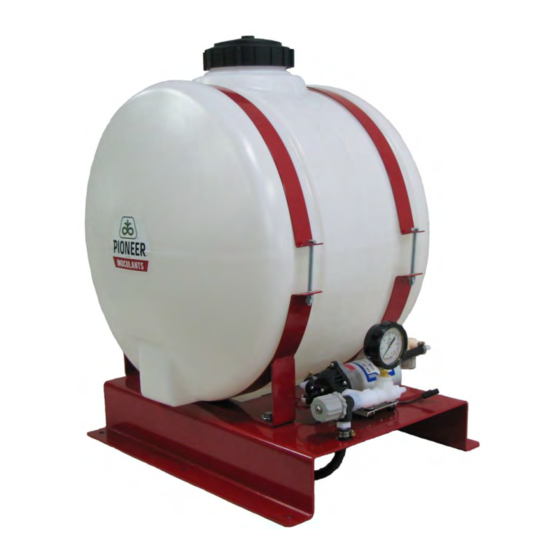
APPLI-PRO BASIC PARTS BREAKDOWN 55 Gallon Base Unit Description Part # Quantity Base 001-4707B Saddle Strap 001-4707A Tank Strap 1 ½ x 34” 001-4402 Tank Lid 6” with Breather 005-9022C Tank 23” x 55 Gallon 005-9203 Tank Fitting ¾” 005-9100 Tank Breather 005-9022B3 Wire Harness... -
Page 19: Control Box
APPLI-PRO BASIC PARTS BREAKDOWN Control Box Description Part # Quantity Control Box complete 030-0457 Control Box knob 008-0923 U-Bracket 001-2012E Pump lead 006-4583 Speed Control knob 006-2022A Switch 006-2196 Crop Eye plug 006-7500Z Speed Control (inside) 006-2022 Power Lead 006-4580C Suction Cup Mount 001-2012SCM... -
Page 20: Pump And Discharge Assemblies
APPLI-PRO BASIC PARTS BREAKDOWN Parts Description Part# Description Part# Mixing Valve 002-4715 Hose Clamp- Mini 003-9002 FPT Tee -½ 003-TT12 Rubber Hose- 3/8” 002-9003AS 30ft Nipple -½ 003-M1212 Nipple- ¾-½ reducing 003-M3412 Fitting 003-A1238 Drain Cap 003-DC12 Nipple- 3/8-1/2 reducing 003-M1238 Drain Cap Washer 003-DCW12... -
Page 21: Nozzle Bar
APPLI-PRO BASIC PARTS BREAKDOWN Nozzle Bar Parts Description Part# Description Part# Nozzle Pipe 001-4707C Hose Clamp- Mini 003-9002 3/8” Elbow Nozzle Body 004-1209VA Tip Check-Valve Only 004-1207-50 3/8” 2-way Nozzle Body 004-1209VB Quik Jet Washer 004-1207W Bar Clamp ½” 004-1209 004-XR11005VS Cap/Gasket Orange 004-1207J... -
Page 22: Hardware
Hose and wires * All products are trademarks of their respective manufacturers. PIONEER® brand products are provided subject to the terms and conditions of purchase which are part of the labeling and purchase documents. ® Trademarks and service marks of Pioneer Hi-Bred. © 2008 PHII.