Panasonic CZ-64ESMC3 Installation Instructions Manual
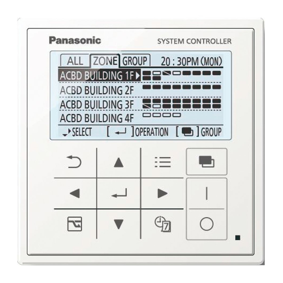
System controller
Hide thumbs
Also See for CZ-64ESMC3:
- Operating instructions manual (64 pages) ,
- Quick reference (56 pages) ,
- Installation instructions manual (248 pages)
Table of Contents
Advertisement
Quick Links
Advertisement
Table of Contents

Related Manuals for Panasonic CZ-64ESMC3


Summary of Contents for Panasonic CZ-64ESMC3
- Page 3 4)/5) FRANÇAIS Bouton Écran Bouton Bouton Boutons Bouton Retour Menu MARCHE/ directionnels Entrée Retourne Affi che Sélectionne Fixe le ARRÊT à l'écran l'écran du un élément. contenu Démarre/Arrête le précédent. menu. sélectionné. fonctionnement. ESPAÑOL Botón Pantalla Botón Botón de Botones de Botón Volver Menú...
- Page 4 Part Names (continued) FRANÇAIS Bouton Indicateur de Bouton Économie d’énergie (Lors de l’utilisation d’un climatiseur minuterie fonctionnement (Vert) avec pompe de chauffage à gaz : S’allume pendant le fonctionnement. Effectue la Passe au fonctionnement effi cace.) Clignote en cas d’alarme. réservation de la Commute entre les modes Normal * Si au moins une unité...
- Page 5 FRANÇAIS Bouton de sélection Commute l’écran. • Commute la cible de l’opération / du réglage entre [Tout], [Zone] et [Groupe]. • Commute l’écran d’opérations de base entre [Opér] (Opération), [ ] (Interdire télécommande) et [[Vent/Div.] (Ventilation/Autre). ESPAÑOL Botón de selección Cambia la pantalla.
-
Page 6: Safety Precautions
ENGLISH Safety Precautions Please Read Before Starting This controller must be installed by the sales dealer or installer. These instructions are all you need for most installation sites and maintenance conditions. If you require help for a special problem, contact our sales/service outlet or your certifi... - Page 7 WARNING Provide a power outlet to be used exclusively for this controller. Turn off the circuit breaker of the controllers before installation. Do not supply power to the controller until all wiring is completed or reconnected and checked. Fix the power supply wiring securely with the clamper so that the power supply terminal board part is free of tension (external force) when pulled.
-
Page 8: Table Of Contents
Central Address Setting ....25 Mounting ......... 15 Outdoor Peak Cut Setting ..... 27 Specifi cations Model No. CZ-64ESMC3 Dimensions (H) 120 mm x (W) 120 mm x (D) 16 + 51.9 mm Weight Temperature/ 0 ˚C to 40 ˚C / 20 % to 80 % (no condensation) Humidity range *Indoor use only. -
Page 9: Air-Conditioning Control System
Air-conditioning Control System The most suitable air-conditioning control system can be selected according to the scale of the control/monitoring area. Controlling indoor units This unit alone enables multi-functional operations: Up to 64 indoor units can be controlled individually or collectively. * 64 indoor units are divided into up to 4 zones, and can be controlled on All, Zone or Group basis. -
Page 10: Dimensions
Dimensions System Controller Switch Box Installation Precautions Installation location Avoid the following locations for installation. • Under direct sunlight • Location near heat source • Uneven surface • Locations where the controller will be splashed with water or affected by dampness or humidity •... -
Page 11: Wiring
Wiring Power supply wiring • Be sure to use a dedicated line for power source. • Be sure to earth this controller. • Do not connect the earth wiring to those of gas pipe, water pipe, lighting rod, telephone, etc. Type of wiring: •... - Page 12 Wiring (continued) Before connecting wiring, be sure to turn the circuit breaker off. After all wiring arrangements are complete, turn the circuit breaker on. If the power supply wiring is mistakenly connected to a terminal board other than the power supply terminal board, the devices to be connected to this controller or this controller will malfunction.
- Page 13 Connecting wiring Remove the 2 screws for fi xing the cover, and remove the power source cover. Connect the power supply wiring to the power supply terminal board. Be sure to connect the earth wiring to the earth terminal. Connect the inter-unit control wiring to the U1 and U2 terminals. When connecting to external equipment, refer to “Connecting to external equipment”...
- Page 14 Wiring (continued) Connecting to external equipment Keep the signal input line lengths to 100 meters or less. For distances greater than this, use a relay. External equipment System controller side Input/Output side Name item Condition Terminal name Circuit example Output Non-voltage contact "a"...
-
Page 15: Mounting
Mounting When mounting the bottom case (step 2) Tighten the screws securely until they reach the bottom case. (Otherwise, loose screw heads may hit the PCB and cause malfunction when mounting the top case.) Do not over-tighten the screws. (The bottom case may be deformed, resulting in fall of the unit.) Embed the included switch box into the wall beforehand. -
Page 16: Setting
Setting Language / Clock / Zone/Group name Press to select [Initial settings]. Select the item to set. Language Set. Clock Set the date and time. Zone/Group name Select the item to set. (EN) - Page 17 Zone name Select the item to give a name to. *Select the zone from zone 1 to 4. Enter the name. (Repeat the same procedure for all character) Group name Select the item to give a name to. *Select the group from group 1 to 64. Enter the name.
-
Page 18: Service Contact
Setting (continued) Service contact / Controller setup Service contact Press and hold the 3 buttons for 4 seconds or more simultaneously. Select [Service contact]. Select the item to set. Enter the name. • Up to 16 characters (Space is included (Repeat the same procedure for all in the number of characters.) -
Page 19: Controller Setup
03 "All/Zone mode" is set to "All mode". System Controller address setting • 0000: Address 1* Up to 10 system controller (CZ-64ESMC3) can be connected on the inter-unit control • 0001 to 0009: Address wiring. When installing more than one unit, assign self addresses to avoid duplication. - Page 20 Setting (continued) *Factory default Item Set contents Set data code • 0000: Display and Flap setting operation enabled* Disables switching operation of airfl ow direction and disables the airfl ow • 0001:Display and display. operation disabled • 0000: No delay* •...
-
Page 21: Test Operation
Test Operation Test operation for the system controller (Preparation) Referring to the operating instructions for indoor units and outdoor units, perform the test operation beforehand. Turn on the system controller (Assigning blinks, and the indoor unit connection group is automatically checked.) Confi... - Page 22 Test Operation (continued) Group Select the operation target. Press to select the zone. Finish the test operation. Perform step 1 and 2, and then select [OFF] in step 4. ([TEST] display disappears.) Attention Do not use this mode for purposes other than the test operation. (To prevent overload of the units) Read the installation instructions supplied with the units.
- Page 23 Indoor unit test operation Performing/Finishing test operation Select All, Zone or Group. Indicator lights up. Press Press Press [All] [Zone] [Group] , and go to ALL. Operate with All. Press Perform test operation. Press Finish the test operation. According to the test operation ON/ OFF procedure, set OFF.
- Page 24 Test Operation (continued) Group Press to select the zone. Select the group from group 1 to 64 to operate. Perform test operation. Displays Press selected group. Finish the test operation. According to the test operation ON/ OFF procedure, set OFF. (EN)
-
Page 25: Central Address Setting
Central Address Setting After the test operation for the air conditioner has fi nished, set the central address according to the following procedure. Press and hold the 3 buttons for 4 seconds or more simultaneously. Select the item to set. * If there is any duplication of central address, this message appears when the individual setting is complete or the... - Page 26 Central Address Setting (continued) When setting the central address from the wired remote control After the setting is complete, turn on the system controller again. Setting from wired remote controllers (CZ-RTC4) Make the setting while stopped. Press and hold the 2 buttons for several simultaneously.
-
Page 27: Outdoor Peak Cut Setting
Outdoor Peak Cut Setting Demand 1 and Demand 2 for outdoor units can be changed. Depending on the type of outdoor unit, it cannot be changed. Press and hold the 3 buttons for 4 seconds or more simultaneously. Select the item to set. * After the setting is complete, this unit and outdoor units restart.