
Related Manuals for JVC 250


Summary of Contents for JVC 250
-
Page 1: Service Manual
SERVICE MANUAL Model 250 Projector 2310 Camino Vida Roble Carlsbad, California 92009 Phone: (760) 929-5300 Fax: (760) 929-5410... -
Page 2: Declaration Of Conformity
© Copyright 1999 by Hughes-JVC Technology Corporation. All worldwide rights reserved. This manual was produced by Hughes-JVC Technology Corporation and may be revised without prior notice. No part of this manual may be reproduced in any form without the express written permission of Hughes-JVC Technology Corporation. -
Page 3: Table Of Contents
5.10 CRT/Yoke Assemblies... 5-51 5.11 VICs ... 5-58 5.12 Backplane ... 5-74 Chapter 6 Miscellaneous Items 6.1 Projector Covers... 6-1 6.2 Electronics Module Tilt-up ... 6-2 6.3 Ventilation... 6-3 6.4 Air Filters ... 6-4 Model 250 Projector Service Manual ... v... - Page 4 Chapter 8 Software and Protocol 8.1 Software Updating... 8-1 8.2 Importing/Exporting... 8-5 8.3 Terminals and Communication Protocol... 8-10 Chapter 9 Parts 9.1 Replacement Parts List... 9-1 9.2 Recommended Spares ... 9-3 Glossary ... A-1 ® Assemblies, and Mirrors... 6-5 Model 250 Service Manual...
-
Page 5: Safety
1.2 Updates... 1-2 1.3 Acronyms Used ... 1-2 The Model 250 Service Manual will provide information on how the each of the different components function individually and how they work together to take a source input image and project that image onto the screen. It will provide a list of the tools and procedures needed to perform necessary adjustments and to remove and replace components. -
Page 6: Updates
CRTs, Arc Lamp or power supplies. Wear safety goggles (rated X5) when working near the light path from the Arc Lamp or at all times around the projection lens. Updates Hughes-JVC will periodically provide bulletins and /or manual supplements to ensure the continued accuracy of this service manual. Acronyms Used ALPS... - Page 7 Scan Reversal Board SYNC Synchronization Transistor-Transistor Logic Underwriter Laboratories Ultraviolet Video Amplifier Board Voltage Controlled Oscillator Video Input Card Video Input Video Processor Board VSYNC Vertical Sync Video Tape Recorder Luminance Model 250 Service Manual Chapter 1---Introduction...
-
Page 8: Introduction
Section, the Electronic Section and the Miscellaneous Items. Each section gives a basic description of the components in the section and a description of the function of those components. This provides an overall view of the projector and its subsystems for a general understanding of how these systems contribute to the function of the projector. -
Page 9: Electrical Section
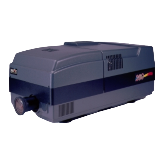
Chapter 2---System Description Figure 2-1 Overview of the Model 250 projector showing major components Electrical Section The electrical section consists of the Incoming Power Circuit, and the Power Supplies and the Igniter Assembly. The following paragraphs give a list of major components and a brief description of those components. -
Page 10: Optical Section
The spark gap produces a high voltage pulse in the Igniter that lights the Arc Lamp. Optical Section The optical section of the Model 250 consists of the Arc Lamp Module, the ® Optical Path, the ILA Arc Lamp Module The Arc Lamp Module supplies high intensity light for the Model 250. -
Page 11: Electronic Section
- Image Light Amplifier (3) ® The ILA is a very important component in the Hughes-JVC projectors. The ® modulates the polarized light from the Arc Lamp. The image light from the CRT that strikes the input side of the ILA ®... -
Page 12: Electronic Section
. The Relay Lens is physically connected to the CRT (see Figure 2-2). Front Projection Lens The Model 250 comes with a choice of four standard lenses. These include a motorized Zoom Lens or one of three Fixed Lenses. All Projection Lenses have motorized focus. - Page 13 Chapter 2---System Description Printed Circuit Boards (PCB) The Model 250 Projector has eight main PCBs: System Controller PCB - System Controller PCB controls much of the electronics system. It uses digital and analog circuitry to generate Menu and internal pattern overlays, and directs convergence correction and shading information.
-
Page 14: Miscellaneous Items
45-ft. line of sight. Cooling Fans The Model 250 has eleven cooling fans of various sizes plus a large blower for the Arc Lamp. The cooling fans maintain thermal stability for the projector. The Arc Lamp especially depends on the cooling fans. - Page 15 EMI Shield The Model 250 has an EMI (Electro-Magnetic Interference) Shield that traps and collects high frequency noise that is radiated by switching power supplies such as the Arc Lamp Power Supply and the Low Voltage Power Supply. This high frequency noise can interfere with the operation of radios, televisions, and other electronic devices.
- Page 16 Chapter 2---System Description Model 250 Service Manual...
-
Page 17: Safety
Safety at the beginning of this manual. WARNING that require projector covers to be off, wear high voltage gloves (ANSI/ASTM 10,000 volt rated) when working near the CRTs, Arc Lamp, or power supplies. Wear safety goggles (rated X5) when working anywhere near the light path from the arc lamp or the projection lens. -
Page 18: Incoming Power Circuit
The AC Circuit Breaker is rated at 90-264 Vac (RMS), 50/60 Hz. The current rating is 13 Amps RMS at 90 Vac. The power requirements of the Model 250 Projector are 200-264 Vac, 50/60 Hz, single phase. The power consumption is rated at 2800-Watts maximum. -
Page 19: Power Supplies
3.3 Power Supplies All Series 200 projectors including the Model 250 have three power supplies. These include: Low Voltage Power Supply Arc Lamp Power Supply High Voltage Power Supply There is a fourth power supply, the Laser Power Supply, but that power supply is used only for the Igniter Assembly during Arc Lamp lighting. - Page 20 The +5.1V Standby is on whenever AC power is connected to the projector and the circuit breaker on the rear panel is in the ON position. When the AC Circuit Breaker is in the ON position, the LVPS supplies the +5.1 V to the System...
- Page 21 Low Voltage Power Supply - p/n 102520 To remove the Low Voltage Power Supply: Power off the projector by IR Remote or PC, and allow the cooling fans to run until they shut off. Turn the AC Circuit Breaker to the OFF position and unplug the AC Power Cord.
- Page 22 Current - 70 to 85 amps to maintain the arc lamp operation. LAMP_OUT - Lamp output voltage, positive. LAMP_RTN - Lamp return. /LAMP_LIT - signal to System Controller PCB indicating that the Arc Lamp is lit. /LAMP_OK - signal to System Controller PCB (no real indication). Model 250 Service Manual...
- Page 23 This high voltage pulse ignites the Xenon Arc Lamp. Immediately after the Arc Lamp lights, the voltage from the Arc Lamp Power Supply drops to about 25-31 volts at 70-85 amps. It will stay at this level during normal Arc Lamp operation. Model 250 Service Manual...
- Page 24 Figure 3-3 Arc Lamp Power Supply connections. ALPS - Service Adjustments The Arc Lamp Power Supply for the Model 250 is preset at the factory and does not have any Service Adjustments. The output is programmed for a constant 2 kW. Arc Lamp replacement does not require any electrical readjustments.
- Page 25 Arc Lamp Power Supply. The other screw was removed with the EMI Shield. Carefully slide the Arc Lamp Power Supply out of the projector. Replace the Arc Lamp Power Supply in the reverse order. High Voltage Power Supply (HVPS)
- Page 26 + 80 V. - The input power for the High Voltage section of the High Voltage Power Supply. HVPS - Outputs G1 Supply - goes to Video Amplifier PCB G2 Supply - goes to Video Amplifier PCB /HV_OK - goes to System Controller PCB 3-10 Model 250 Service Manual...
- Page 27 High Voltage Power Supply (see Figure 3-5) that adjust the focus for each CRT. The CRT Focus Voltage adjustments are detailed in the CRT Section (see section 5.10 CRT/Yoke Assemblies). Model 250 Service Manual Chapter 3---Electrical 3-11...
- Page 28 High Voltage Power Supply p/n 102566 To remove the High Voltage Power Supply: Power off the projector by IR Remote or PC, and allow the cooling fans to run until they shut off. Turn the AC Circuit Breaker to the OFF position and unplug the AC Power Cord.
- Page 29 Disconnect P44-G2 Out (at the middle-front of the HVPS). Unsnap the cable clamp at the top of the HVPS. Remove the Anode Cables and the P44 cable from the cable clamp. Model 250 Service Manual Chapter 3---Electrical PIN # Description...
- Page 30 HVPS is free to be removed. Loosen (do not remove) the two Posi-drive screws (at the bottom of the HVPS) that secure the HVPS metal housing to the projector. Remove the two Posi-drive screws that hold the top of the HVPS metal housing to the projector frame.
-
Page 31: Igniter Assembly
(secondary) coil. The high voltage pulse goes to the Anode of the Arc Lamp. The spark generated by the 32 kV pulse creates an arc inside the Xenon bulb that ignites the Arc Lamp. Model 250 Service Manual Chapter 3---Electrical 3-15... - Page 32 Igniter Assembly p/n 106570 To remove the Igniter Assembly 1. Power the projector Off by IR Remote or PC, and allow the cooling fans to run until they shut off. 2. Turn the AC Circuit Breaker to the OFF position and unplug the AC Power Cord.
- Page 33 Arc Lamp Power Supply. 7. Remove the five #1 Pozi-drive Phillips-head screws. 8. Lift the Igniter Assembly out of projector. 9. Reverse the procedure to install the Igniter Assembly. Model 250 Service Manual Chapter 3---Electrical 3-17...
-
Page 34: Optical Path
Do not open the lamp housing or attempt to replace the Arc Lamp inside its module! Do not touch the Arc Lamp, or any connections, when the lamp is ignited or is arcing. Any servicing of the Arc Lamp must remain restricted to Hughes-JVC Certified Technicians. Model 250 Service Manual... -
Page 35: Arc Lamp
It supplies the high intensity white light used by the projector to put a very bright image on the screen. The expected 50% life (half of initial light output) of an Arc Lamp is approximately 1000 hours. - Page 36 Lamp. Protect eyes from ultra violet light and infrared light by using X5 (375 to 700 nanometers), ANSI approved, shade goggles when actually working on the projector near the arc lamp source. 6. Access the "Shutters on Hide" box again from the System-Preferences menu and uncheck the box, then use the RGB and HIDE keys to hide Green.
- Page 37 Chapter 4---Optical Figure 4-1 Arc Lamp “Hot Spot” (brightest area) is off-center vertically and horizontally. Adjust to center the “hot spot”. Figure 4-2 Arc Lamp alignment fixture. Hot spot off-center Model 250 Service Manual...
- Page 38 AC outlet. To Remove the Arc Lamp: Power off the projector by IR Remote or PC, and allow the cooling fans to run until they shut off. Turn the AC Circuit Breaker to the OFF position but leave the AC Power Cord plugged in to maintain chassis ground.
- Page 39 Remove the two retaining bolts for the Arc Lamp, using a 10-mm socket and driver. Reverse the procedure to install the Arc Lamp. Check and adjust the Arc Lamp alignment after replacing. There is no Arc Lamp current adjustment. Model 250 Service Manual...
-
Page 40: Optical Path
Separates the white light into its RGB component colors using Dichroic Beamsplitters. Polarizes each of the component RGB light beams Combines the component RGB image beams into one beam and delivers that to the Projection Lens. Model 250 Service Manual ® to the Projection Lens Chapter 4---Optical... - Page 41 ILA After being positioned by the Condensing Lens, the light then reflects off two more Cold Mirrors, losing more Infrared light. It passes through another Condensing Lens and into the Dichroic Beamsplitter Assembly. ® ® ® Model 250 Service Manual...
- Page 42 DO NOT open any of the Optical Support Assembly covers while the projector is ON. The bright light can cause severe eye damage. Model 250 Service Manual...
- Page 43 Chapter 4---Optical Figure 4-6 Optical Path 4-10 Model 250 Service Manual...
- Page 44 No serviceable parts The one adjustment that can be performed on the optical path is with the XY Positioner that moves the #1 Condensing Lens in the X- and Y-axis. The XY Model 250 Service Manual Figure 4-7 Optical Path Chapter 4---Optical...
- Page 45 Lamp alignment difficult or impossible. To adjust the XY Positioner: 1. Turn the projector ON and allow it to stabilize for at least 15 minutes. 2. Check the screen for dark edges on the top, bottom, left, or right. Check...
-
Page 46: Ila
Bias Voltage and Frequency - 10-13 Vac at 2 kHz ® Outputs Image light - High intensity polarized image light output to the Prism Assembly and then to the Projection Lens and screen. Model 250 Service Manual ® Sensitivity) ® ®... - Page 47 Bias and Sensitivity Adjustment ® The ILA has adjustable bias and frequency (sensitivity). The ILA sensitivity are adjusted by software through the menu (see Model 250 User’s Guide, section 5.6 Setup Adjustments). The ILA ® for each ILA ; the ILA ®...
- Page 48 NOTE: Reset the ILA Sensitivity Offset, and Threshold Offset level (see Model 250 User’s Guide, section 5.8 Black Level G ® Overlap This adjustment positions the ILA ® from each ILA will overlap (be placed on top of) the other two ILA...
- Page 49 ILA . They are visible only after the ILA 13. If the overlap is at the top or bottom, be sure the projector is level. Slide the spring clip (see Figure 4-10) at the top of the ILA 14. Loosen the two hex nuts, using a 4-mm hex-head wrench.
- Page 50 To adjust the ILA Back Focus for a Zoom Lens: 1. Power the projector ON and allow to stabilize for at least 15 minutes 2. Remove the Rear Cover and tilt up the Electronic Module. 3. Hide Red and Blue. View Green.
- Page 51 To adjust the ILA Back Focus for a Fixed Lens: 1. Power the projector ON and allow it to stabilize for 15 minutes. 2. Remove the rear cover and tilt up the Electronic Module. 3. View Green. Hide Red and Blue.
- Page 52 Disconnect the connector from the ILA (it will slide out with some resistance). It will be necessary to reset ILA setting, and shading for the ILA Model 250 Service Manual ® /Lens/CRT assembly forward or backward to achieve ® Assembly and the wing nut on ®...
-
Page 53: Relay Lenses
Prism Assembly where the red, green, and blue image light are combined. The Projection Lens focuses this output image light onto the screen. All Projection Lenses come with motorized focus adjustment. The Model 250 projector comes with a choice of four standard lens options. Motorized Zoom Lens 2:1 - 4:1 Fixed Lenses 0.96: 1... - Page 54 NOTE: Use the same procedure to install or remove fixed lenses. Also, when changing from a zoom to a fixed lens, or vice versa, check the ILA Back Focus adjustment (see section 4.3 ILA Model 250 Service Manual Chapter 4---Optical ®...
- Page 55 Chapter 5 Optical 3-4-22 Model 100 Service Manual...
-
Page 56: Safety
Safety at the beginning of this manual WARNING!!! that require projector covers to be removed, wear high voltage gloves (ANSI/ASTM 10,000 volt rated) when working near the CRTs, Arc Lamp, or power supplies. Wear safety goggles (rated X5) when working anywhere near the light path from the arc lamp or the projection lens. -
Page 57: Leds
Direct exposure to light of this brightness can cause severe eye injury. Introduction The Model 250 Electronics System includes nine printed circuit assemblies. They provide all the controlling voltages and signals to adjust and correct picture settings, geometry, convergence, and shading (see Chapter 4 of the User’s Guide). -
Page 58: System Controller Pcb
Figure 5-2 Model 250 Electronics Module with PCBs (side view). CAUTION data be downloaded (Exported, see section 8.2 Importing/Exporting) before performing any of the following procedures. Exporting baseline source setup data to disk is an excellent precautionary measure. It will save the... - Page 59 External Service Mode Switch. Pressing this switch during a power-up sequence brings the system up in a diagnostic mode (for maintenance) rather than a normal operating mode. Figure 5-3 Rear of Electronics Module with rear cover and panel removed. Model 250 Service Manual...
- Page 60 Chapter 5---Electronics Figure 5-4 System Controller PCB I/O Diagram for Power Supplies and peripherals. Model 250 Service Manual...
-
Page 61: System Controller Pcb
Controller PCB that the Arc Lamp is lit. ODD_FIELD - Square wave signal from the Raster Timing Generator PCB, with 50% duty cycle that is low during odd fields of an Interlace signal. This signal is high during noninterlaced signals. Model 250 Service Manual... - Page 62 RGB_OVER - signal to Video Processor PCB for the On-screen Menu and /or Internal Test Pattern for red, green, and blue. OVERLAY - signal to the Video Processor PCB, to switch between internal and external sources. Model 250 Service Manual...
- Page 63 RGB_SHUT - Signal to operate the red, green, and blue shutters. LENS_ZOOM - Signal to the zoom motor of the Projection Lens. LENS_FOCUS - Signal to the focus motor of the Projector Lens. System Controller PCB - Operation Startup Functions When AC Circuit Breaker is powered ON, the Low Voltage Power Supply sends +5.1 V stdby voltage to the System Controller PCB.
- Page 64 PC. Commands issued from the IR remote controls are received through IR Detectors located on the front and rear of the projector. Commands issued from a PC, Laptop, or Tethered Remote Control are received through the RS-232 serial interface ports.
- Page 65 If there is a new release of system software, it can be uploaded into the projector by switching into the diagnostic mode. The procedure for this is in the Software and Protocol section (see Chapter 8, Software and Protocol).
-
Page 66: Video Processor Pcb
IIC_DATA - IIC data line. Bi-directional serial line for synchronous data transfer between the System Controller PCB and Video Processor PCB. IIC_CLK - IIC clock line. Unidirectional clock line for control of synchronous data transfer over IIC bus. Model 250 Service Manual Chapter 5---Electronics 5-11... -
Page 67: Diagrams
Chapter 5---Electronics Figure 5-7 Video Processor PCB I/O diagram for VICs and Power Supplies. 5-12 Model 250 Service Manual... -
Page 68: Video Processor Pcb
GRN_SYNC - sync-on-green sync pulse goes to the Raster Timing Generator PCB. RESTORE - DC Restore control signal to the Video Amplifier PCB. This signal controls the DC level of the image signal, clamping it to the proper level on the Video Amplifier PCB. Model 250 Service Manual 5-13... - Page 69 The Video Processor PCB accepts image and synchronizing inputs in either composite or separate RGBHV component format from the selected VIC. When the projector receives the power ON command, the System Controller PCB polls the VICs to determine what VICs are available. It then activates the VIC selected in the Channel Menu (see section 4-6 in the User’s Guide).
- Page 70 Video Processor PCB - p/n 105234 To remove the System Controller PCB: 1. Power off the projector by IR Remote or PC, and allow the cooling fans to run until they shut off automatically. 2. Turn the AC Circuit Breaker to the OFF position and unplug the AC Power Cord.
-
Page 71: Raster Timing Generator Pcb
Generates horizontal line count and vertical count Provides IIC interface Generates clamp pulse Detects changes in source Generates HVPS_SYNC signal Enables horizontal deflection (/H_ENA) circuitry Figure 5-10 Raster Timing Generator I/O diagram for Power Supplies. 5-16 Model 250 Service Manual... -
Page 72: Raster Timing Generator Pcb
H_SYNC - input horizontal sync from the Video Processor PCB. G_SYNC - Sync-on-Green sync stripped from green video signal at the Video Processor PCB. ISYNC - 5 MHz clock from the System Controller PCB used to generate the internal sync. Model 250 Service Manual 5-17... - Page 73 Horizontal Vertical Deflection PCB. HVPS_SYNC - synchronization pulse for High Voltage Power Supply, synchronized with the selected horizontal sync at the same, half, or one third the frequency. 5-18 Model 250 Service Manual...
- Page 74 High Voltage Power Supply is phase locked to the incoming horizontal frequency by the HVPS_SYNC signal. The horizontal flyback time gets shorter as the horizontal scan frequency increases. The Raster Timing Generator PCB works together with the Horizontal Model 250 Service Manual Chapter 5---Electronics 5-19...
- Page 75 Raster Timing Generator PCB - p/n 105238 To remove the Raster Timing Generator PCB: Power OFF the projector by IR Remote or PC, and allow the cooling fans to run until they shut off automatically. Turn the AC Circuit Breaker to the OFF position and unplug the AC Power Cord.
-
Page 76: Horizontal Vertical Deflection Pcb
FRONT/REAR - front or rear projection status line from the Scan Reversal PCB. (FRONT = low, REAR = high). FLOOR/CEILING - floor or ceiling projection status line from the Scan Reversal PCB. (FLOOR = low, CEILING = high). Model 250 Service Manual Chapter 5---Electronics 5-21... - Page 77 ±15 V - input power from the Low Voltage Power Supply, for the analog circuitry. +5.1 V - input power from the Low Voltage Power Supply, for the digital circuitry. Figure 5-13 Horizontal/Vertical I/O Diagram. 5-22 Model 250 Service Manual...
- Page 78 Chapter 5---Electronics Figure 5-14 Horizontal/Vertical I/O Diagram for Scan Reversal and Video Amplifier PCBs. Model 250 Service Manual 5-23...
-
Page 79: Horizontal Vertical Deflection Pcb
PCB to power analog circuitry. +5.1 V - pass through voltage from Low Voltage Power Supply to Scan Reversal PCB to power digital circuitry. H_CUR_FDBK - current feedback to horizontal waveform amplifier. 5-24 Vertical Adjustment Pots Model 250 Service Manual... - Page 80 Raster Timing Generator PCB. The Convergence Deflection PCB sends this waveform along with a parabola waveform V_PARAB to the vertical deflection amplifier on the Horizontal Vertical Deflection PCB. The Horizontal Vertical Deflection PCB takes V_RAMP, amplifies it and adds geometric correction with Model 250 Service Manual 5-25...
- Page 81 1. Remove the rear cover and pull the Interlock switch out to the Service Mode position. 2. Power ON the projector by IR Remote or PC, and allow it to stabilize for a minimum of 15 minutes 3. Use the X-hatch test pattern.
- Page 82 If Red is higher than Green at the top and bottom, or lower than Green at the top and bottom, the Red image may not being centered correctly. This can be corrected with the centering adjustment (see Model 250 User’s Guide, Chapter 5).
-
Page 83: Convergence Deflection Pcb
Horizontal Vertical Deflection PCB p/n 105236 To remove the Horizontal/Vertical (H/V) Deflection PCB: 1. Power off the projector by IR Remote or PC, and allow the cooling fans to run until they shut off automatically. 2. Turn the AC Circuit Breaker to the OFF position and unplug the AC Power Cord. -
Page 84: Convergence Deflection Pcb
Power Supply. V_RAMP - vertical ramp waveform to the Horizontal Vertical Deflection PCB (about 4 Vpp). V_PARABOLA - vertical parabola waveform to the Horizontal Vertical Deflection PCB (about 4 Vpp). Model 250 Service Manual Chapter 5---Electronics ® assembly drivers ®... - Page 85 Chapter 5---Electronics Figure 5-19 Convergence Deflection PCB I/O Diagram. 5-30 Model 250 Service Manual...
- Page 86 Chapter 5---Electronics Figure 5-20 Convergence Deflection PCB I/O Diagram. Model 250 Service Manual 5-31...
- Page 87 ® the ILA . It sends the Convergence Deflection PCB a signal that adjusts the green ® bias to compensate for temperature variations inside the projector. If the 5-32 bias square wave is referred to as ILA ® s and is received from the IIC interface.
- Page 88 Convergence Deflection PCB p/n 105210 To remove the Convergence/Deflection PCB: 1. Power off the projector by IR Remote or PC, and allow the cooling fans to run until they shut off automatically. 2. Turn the AC Circuit Breaker to the OFF position and unplug the AC Power Cord.
-
Page 89: Scan Reversal Pcb
H_RGB_YOKE (neg.) - bottom of red, green, and blue horizontal deflection yokes. V_RGB_YOKE (neg.) - bottom of red, green, and blue vertical deflection yokes. X_RGB_YOKE (neg.) - bottom of red, green, and blue x-axis convergence yokes. 5-34 Model 250 Service Manual... - Page 90 RGB_LOCK (pos.) - interlock for red, green, and blue yokes (5 V when closed or 15 V when open). X_RGB_YOKE (pos.) - top of red, green, and blue x-axis convergence yokes. Y_RGB_YOKE (pos.) - top of red, green, and blue y-axis convergence yokes. Model 250 Service Manual 5-35...
- Page 91 Chapter 5---Electronics Figure 5-22 Scan Reversal PCB I/O Diagram. 5-36 Model 250 Service Manual...
- Page 92 Chapter 5---Electronics Figure 5-23 Scan Reversal PCB I/O Diagram for Horizontal Vertical Deflection PCB. Model 250 Service Manual 5-37...
- Page 93 Scan Reversal PCB. J100 and J101 are for horizontal scan connections. J53 and J53A are the vertical scan connections, and J50 and J50A are convergence jumper connections. The Model 250 comes set for 5-38...
- Page 94 CRT. If any of the deflection yokes are not properly or securely installed, the H_LOCK- signal shuts down the horizontal amplifier on the Horizontal Vertical Deflection PCB (see CRT Protection section of Ch. 7-- Troubleshooting). Model 250 Service Manual 5-39...
- Page 95 4. Remove the rear cover and pull the Interlock switch out to the Service Mode position. 5. Power ON the projector by IR Remote or PC, and allow it to stabilize for a minimum of 15 minutes 6. Use the X-hatch test pattern.
- Page 96 The Horizontal Scan Reversal Jumper reverses the image projection for front or rear projection. Figure 5-25 illustrates the jumpers’ location on the Scan Reversal Board. The Model 250 Projector is shipped with the jumper plugs inserted in J50 and J100 for front/upright projection (see Table 5-1 for other orientations).
- Page 97 Figure 5-21 illustrates the location of the jumpers on the Scan Reversal Board. The Model 250 Projector is shipped in the normal vertical projection position with the jumper plug inserted into J53. For an inverted vertical setup this jumper plug must be inserted into JA53.
-
Page 98: Video Amplifier Pcb
Scan Reversal PCB p/n 102585 To remove the Scan Reversal PCB: 1. Power off the projector by IR Remote or PC, and allow the cooling fans to run until they shut off automatically. 2. Turn the AC Circuit Breaker to the OFF position and unplug the AC Power Cord. - Page 99 ±15 V - input power for the analog circuitry from the Low Voltage Power Supply. 6.2 V - input power for the CRT filaments heaters from the Low Voltage Power Supply. 5-44 grid on CRTs from High Voltage Power Supply grid on CRTs from High Voltage Power Supply Model 250 Service Manual...
- Page 100 Chapter 5---Electronics Figure 5-26 Video Amplifier PCB I/O Diagram Model 250 Service Manual 5-45...
- Page 101 RGB_CATHODE - image output signal to CRTs (about 40 Vpp with peak voltage of 70 V). RGB_G voltage to CRTs (Blanking pulse to CRT). RGB_G voltage for CRTs (about 600-800 V). RGB_HEAT (pos.) - positive side of the CRT heater voltage (about 6.2 V). 5-46 Model 250 Service Manual...
- Page 102 The/SWEEP_OK from the Horizontal Vertical Deflection PCB becomes /VA_OK on the Video Amplifier PCB. If the /VA_OK goes high, the Video Amplifier PCB shuts down the G and G regulators effectively shutting down the all the CRTs. Model 250 Service Manual 5-47...
- Page 103 PCB. The Video Processor PCB compares the beam current to a reference value (250 µA). If the beam current of any CRT meets or exceeds that reference value, the Video Amplifier PCB reduces the Contrast of the CRTs (a global adjustment) until the beam current is below the reference.
- Page 104 Green CRT and the ground wire still connected from the CRT/Yoke Assembly to the CRT Socket Connector. The Green CRT Socket Connector is close to the rear of the projector. It is easier to disconnect it from the CRT after the CRT/Yoke Assembly is loose and moved away from the rear of the projector (see CAUTION below).
- Page 105 PCB toward the left so the mounting screws will clear the access holes and remove the board from the projector. 15. Reinstall in the reverse order from above. Figure 5-28 Video Amplifier PCB showing CRT Socket Connectors. 5-50 Model 250 Service Manual...
-
Page 106: Crt/Yoke Assemblies
Y_RGB_YOKE (neg.) - bottom of red, green, and blue Y-axis Convergence yokes. From CRTs RGB_HEAT (neg.) - negative side of CRTs heater voltage (0 V). ARC_GND - CRTs ground (Anode supply return line). Model 250 Service Manual Chapter 5---Electronics 5-51... - Page 107 Loosening the setscrews to perform one adjustment may cause the other adjustment to change; therefore, both adjustments should be performed at the same time. 5-52 ® and the Cathode to modulate brightness. Model 250 Service Manual grid works with G...
- Page 108 2. Pull the Interlock Switch for the rear cover up to the Service Mode position. 3. Power the projector ON and allow it to stabilize for at least 15 minutes. 4. Tilt the Electronic Module to the full up position.
- Page 109 To perform the CRT Rotation adjustment: 1. Remove the rear cover. 2. Power the projector ON and allow it to stabilize for at least 15 minutes. 3. Tilt the electronic module to the full up position. 4. Select Center/Lin pattern (test pattern #8).
- Page 110 Recheck Bow, Pincushion, Keystone, and Skew and readjust if necessary. Also recheck Convergence (see the Setup Adjustments section, Chapter 5 in the Model 250 User’s NOTE: If replacing a CRT/Yoke Assembly, the horizontal size coils on the Scan Reversal PCB may need adjustment to compensate for the new yokes.
- Page 111 To perform the Electronic Focus adjustment: Remove the front and rear cover. Power the projector ON and allow it to stabilize for at least 15 minutes. Select the Focus pattern (test pattern #6). Zoom the Projection Lens to the widest angle and adjust the Projection Lens focus for the sharpest image.
- Page 112 CRT p/n 105199 To remove and replace a CRT: Power OFF the projector by IR Remote or PC, and allow the cooling fans to run until they shut off automatically. Turn the AC Circuit Breaker to the OFF position and unplug the AC Power Cord.
-
Page 113: Vics
Adjustment Coils on the Scan Reversal PCB if necessary. 5.11 Video Input Cards (VICs) The VIC is the interface between the input source and the projector. Several input source format are accepted such as separate RGBHV, Composite, YPbPr, and S- Video. -
Page 114: Standard Rgbhv Vic
YPbPr (Optional) Quad Standard Decoder (Optional) Quad Standard Decoder/Line Doubler (Optional) The are three VICs slots on the Model 250, however the 4-Input RGBHV, and the Quad Standard Decoder/Line Doubler require two slots. Standard RGBHV VIC RGBHV VIC - Main Functions... - Page 115 A green LED is illuminated when the VIC is selected. RGBHV VIC - Service Adjustments There are no service adjustments on the RGBHV VIC RGBHV VIC - Remove and Replace Tools Needed #0 Posi-drive Phillips-head screwdriver 5-60 Model 250 Service Manual...
- Page 116 RGBHV VIC p/n 102597 To remove the RGBHV VIC: 1. Power off the projector by IR Remote or PC, and allow the cooling fans to run until they shut off. 2. Turn the AC Circuit Breaker to the OFF position and unplug the AC Power Cord.
- Page 117 BLU_VIC - blue image to the Video Processor PCB (0.7-1.0 Vpp). H_VIC - horizontal sync to the Video Processor PCB V_VIC - vertical sync to the Video Processor PCB /SEL_VIC - VIC select line to the Video Processor PCB 5-62 Model 250 Service Manual...
- Page 118 Graphics Enhancer Plus VIC p/n 106183 To remove the RGBHV VIC: 1. Power off the projector by IR Remote or PC, and allow the cooling fans to run until they shut off automatically. 2. Turn the AC Circuit Breaker to the OFF position and unplug the AC Power Cord.
-
Page 119: 4-Input (Quad) Rgbhv Vic
H - horizontal sync from source input V - vertical sync from source input +15 V - power for analog circuitry -15 V - power for analog circuitry +5.1 V - power for digital circuitry +5.1 V Stdby 5-64 Model 250 Service Manual... - Page 120 Chapter 5---Electronics IIC CLK - IIC clock line IIC DATA - IIC data line IIC SINT - IIC interrupt line Figure 5-36 4-Input (Quad) RGBHV VIC. Model 250 Service Manual 5-65...
- Page 121 4-Input (Quad) RGBHV VIC p/n 103668 To remove the RGBHV VIC: 1. Power off the projector by IR Remote or PC, and allow the cooling fans to run until they shut off automatically. 2. Turn the AC Circuit Breaker to the OFF position and unplug the AC Power Cord.
-
Page 122: Ypbpr Vic
Separation of syncs from the Y/G input signal Hue, sharpness, gamma, and color adjustment Selection of RGB component input or YPbPr input LED indication IIC serial bus interface Figure 5-37 YPbPr VIC I/O Diagram. Model 250 Service Manual Chapter 5---Electronics 5-67... - Page 123 This VIC accepts two input signal formats, YPbPr and GBR signals. The YPbPr VIC converts either input signal format to the RGB format. The selection of the VIC and inputs is controlled by the System Controller Board via the IIC serial bus 5-68 Model 250 Service Manual...
- Page 124 YPbPr VIC p/n 106340 To remove the YPbPr VIC: 1. Power off the projector by IR Remote or PC, and allow the cooling fans to run until they shut off automatically. 2. Turn the AC Circuit Breaker to the OFF position and unplug the AC Power Cord.
-
Page 125: Quad Standard Decoder Vic
Separation of syncs from the input signal Tint, sharpness, and color adjustment LED indication of Composite or S-video IIC serial bus interface Figure 5-39 Quad Standard Decoder VIC faceplate. Figure 5-40 Quad Standard Decoder I/O Diagram. 5-70 Model 250 Service Manual... - Page 126 The Quad Standard Decoder VIC has two LEDs. The Composite LED illuminates green when the Composite input is selected. The S-image LED illuminates green Model 250 Service Manual 5-71...
-
Page 127: Quad Standard Decoder/Line Doubler Vic
Quad Standard Decoder VIC p/n 103545 To remove the Quad Standard Decoder VIC: 1. Power off the projector by IR Remote or PC, and allow the cooling fans to run until they shut off automatically. 2. Turn the AC Circuit Breaker to the OFF position and unplug the AC Power Cord. - Page 128 The blank faceplate is not included with the Quad Standard Decoder/Line Doubler VIC unless it is installed at the factory. The part number for the blank faceplate is p/n 102667. Figure 5-41 Quad Standard Decoder/Line Doubler VIC faceplate with blank faceplate above it. Model 250 Service Manual 5-73...
-
Page 129: Backplane Pcb
5.12 Backplane PCB The Backplane PCB is the spine of the Electronics Module. Every major electronic component in the Model 250 projector connects to and through the Backplane PCB. It is hidden in the inside of the Electronics Module (see Figure 5-2). - Page 130 /FAN_ENA Arc Lamp Power Supply (9) Pin # Signal or Voltage /LAMP_LIT /LAMP_OK /LAMP_ENA /COVER_ON 1, 6 Model 250 Service Manual Chapter 5---Electronics High Voltage Power Supply (J7) Pin # Signal or Voltage /HV_OK +80 V +15 V -15 V...
- Page 131 Chapter 5---Electronics Figure 5-44 Backplane Diagram (right side). 5-76 Model 250 Service Manual...
- Page 132 Chapter 5---Electronics Model 250 Service Manual 5-77...
-
Page 133: Projector Covers
6.7 Cleaning Lenses, ILA Projector Covers There are two projector covers, one that covers the front of the projector and one that covers the rear. The are attached and hinged to the Cross-Member Assembly. The covers can be tilted up (see CAUTION below) or removed from the projector to perform service procedures. -
Page 134: Electronics Module Tilt-Up
Electronics Module Tilt-up The Electronics Module contains all the electronic Printed Circuit Boards for the Module 250 Projector except for the Video Amplifier PCB and its three associated CRT socket PCBs. It is located in the rear of the projector. The... -
Page 135: Ventilation
Figure 6-1 Electronics Module hinge and locking mechanism. Ventilation Adequate cooling is a major consideration for the Model 250 projector. There are thirteen cooling fans (including the Arc Lamp blower) in this projector. 4 fans in the main chassis - two in the rear of the projector, one in the right front corner and one on the bottom of the projector. -
Page 136: Air Filters
The IR Detectors receive command signals from the IR Remote Control. The Model 250 projector has two IR Detectors, one on the front of the projector and one on the rear (mounted on the System Controller PCB). The command signals go to the System Controller PCB where they are distributed to the various PCBs, typically by way of the IIC data bus. -
Page 137: Cleaning Lenses, Ila Assemblies, And Mirrors
Mirrors and Polarizing Beam Splitter Windows - The Optical Shields cover the Dichroic Mirror Assembly and Polarizing Beam Splitter windows. Normally cleaning is not needed. Clean only if absolutely necessary using compressed air. Do not wipe mirrors. Model 250 Service Manual Chapter 6---Miscellaneous Items ® Assemblies and Mirrors ®... - Page 138 Chapter 6---Miscellaneous Items Model 250 Service Manual...
-
Page 139: Model 250 Service Manual
Safety at the beginning of this manual. WARNING procedures that require projector covers to be off, wear high voltage gloves (ANSI/ASTM 10,000 volt rated) when working near the CRTs, Arc Lamp, or power supplies. Wear safety goggles (rated X5) when working anywhere near the light path from the arc lamp or the projection lens. -
Page 140: Leds
Backpanel LEDs This section covers the various terminals, detectors, and LEDs visible from the rear and left side of the projector with the rear projector cover and rear panel removed. Operation Status LED - This LED indicates the status of the projector. When the LED is illuminated green, the projector is operating normally. - Page 141 Terminal In port except that it can not be used to Import/Export setup data. Tethered Remote Jack - The Model 250 projector is shipped with an IR Remote Control. This IR Remote can be used with an optional 150 ft. cable that will plug in the Tethered Remote Jack.
- Page 142 Figure 7-2 Dip Switch Block on System Controller PCB. Reset Switch - The Reset Switch resets the CPU if the projector locks up and does not respond to an IR Remote, PC or Laptop computer. If the rear panel is in place, the CPU can also be reset by cycling the AC Circuit Breaker off and back on again.
-
Page 143: Video Processor Pcb Leds
Video Processor - Test Points The test points on the Video Processor PCB are visible and accessible from the left side of the Electronics Module when the rear projector cover is removed. The test points can be grouped into four categories:... - Page 144 LED will be illuminated orange if any of the CRTs is at or exceeding beam current limit (250 µA). If any of the CRTs is at the beam current limit, the Video Processor will reduce Contrast. If reducing Contrast does not bring down the beam current for that CRT, the Video Processor PCB will reduce G2 voltage.
-
Page 145: Raster Timing Generator Pcb Leds
Chapter 7---Troubleshooting Raster Timing Generator PCB LEDs Figure 7-6 Raster Timing Generator LEDs. Model 250 Service Manual... - Page 146 Raster Timing Generator PCB LEDs Band LEDs The range horizontal scan frequencies accepted by the Model 250 projector is divided into four “bands”. The four LEDs (A, B, C, & D) toward the front of the projector on the Raster Timing Generator PCB indicate which range of horizontal scan frequencies the input source is operating.
-
Page 147: Convergence Deflection Pcb Leds
Chapter 7---Troubleshooting Convergence Deflection PCB LED Figure 7-7 Convergence Deflection PCB LED. The Convergence Deflection PCB has only one LED. It illuminates green when power (±15 V) is present on the PCB. Model 250 Service Manual... -
Page 148: Video Amplifier Pcb Leds
CRT deflection circuits are operating properly (/DEFL_OK), the supply voltages (±15 V, +6.2 V, and +80 V) are present at the Video Amplifier PCB, and all the CRT Yoke connectors are properly installed (see Figure 7-15 and Figure 7-16). 7-10 Model 250 Service Manual... -
Page 149: Backplane Pcb Leds
Power Supply, and the /HV_OK signal from the High Voltage Power Supply. The Backplane also has several connectors that can be used for probing signals and voltages (see Figure 7-18 and associated signals and voltages). Model 250 Service Manual 7-11... -
Page 150: Diagrams
ON until approximately ten minutes after the projector receives a power Off command (AC Circuit Breaker still on). When the projector receives a power ON command from the IR Remote, PC or Laptop, the System Controller PCB receives a /LAMP_OK from the Arc Lamp Power Supply. - Page 151 The voltage from the Arc Lamp Power Supply stays at a steady output of 2 kW during normal operation of the projector. When the projector receives a power OFF command, the /LAMP_LIT and the /LAMP_ENA signal both go high. This shuts off the Arc Lamp Power Supply.
-
Page 152: Image Path
The horizontal and vertical sync pulses are routed to the Raster Timing Generator PCB. In the case of Sync-on- Green type sync pulses, the horizontal and vertical syncs are stripped from the green image signal in the Video Processor PCB. 7-14 Model 250 Service Manual... -
Page 153: Deflection Path
CRT Yokes. Many of the geometric corrections are integrated into the horizontal waveform at the Horizontal Vertical Deflection PCB such as Pincushion, Keystone, Skew, and Bow. The vertical size is be adjusted on the Horizontal Vertical Deflection PCB. Model 250 Service Manual 7-15... - Page 154 Scan Reversal PCB to the Convergence Yokes on each CRTs. The Scan Reversal PCB sends the horizontal and vertical deflection waveforms to the appropriate CRT. It also converts the waveform for floor/ceiling and front/rear projector installations. 7-16 Model 250 Service Manual...
- Page 155 Chapter 7---Troubleshooting Figure 7-13 CRT Deflection path between Horiz/Vert Deflection PCB, Convergence Deflection PCB and Scan Reversal PCB. Model 250 Service Manual 7-17...
- Page 156 Chapter 7---Troubleshooting Figure 7-14 CRT Deflection path between the Scan Reversal PCB and CRT. 7-18 Model 250 Service Manual...
-
Page 157: Crt Protection
If DEFL_OK goes low or /H_ENA goes high, the output /SWEEP_OK goes high. If the /SWEEP_OK signal, on the Video Amplifier PCB, goes high, the G supply and the G Regulator circuit shut down. On the Video Model 250 Service Manual 7-19... - Page 158 (RED, GRN, and BLU BEAM) from each image amplifier circuits. The Video Processor PCB receives these current sense lines and compares them to a reference. If the beam current of any CRT exceeds 250 µA, the Beam current LED illuminates orange, and the Video Processor PCB reduces Contrast. If reducing Contrast does not bring the CRT beam current below 250 µA, the Video...
- Page 159 Chapter 7---Troubleshooting Figure 7-16 CRT Protection path between the Scan Reversal PCB and CRT. Model 250 Service Manual 7-21...
-
Page 160: Error Codes
Chapter 7---Troubleshooting 7.4 Error Codes For certain errors that may occur in the Model 250 Projector the software provides error codes that are helpful in determining the nature of the problem. These error codes can be seen on the left side of the monitor screen when using a PC connected to Port A or Port B. - Page 161 “RTG PCA Not OK” 4.14 “Lamp Startup” 4.15 “Low Voltage PS” 4.16 “High Voltage PS” Model 250 Service Manual Chapter 7---Troubleshooting Software error-no heap available for memory allocation. Software error-invalid Flash sector number. Flash Memory Write Failure. Flash Memory Erase Sector Failure.
- Page 162 No Header found in data stream - possible baud rate error. Expected data characters to be repeated - failed. Data not in Extron or JVC Switcher format. Ansi Output to RS232 port was interrupted - incomplete. User has selected a Channel - VIC is not present.
-
Page 163: Troubleshooting Guide
7.5 Troubleshooting Guide Table 7-3 lists some common projector problems, what to check when problems occur, and offers possible solutions. It indicates the section in this Service Manual that provides some related information on the problem. If the User’s Guide contains pertinent information, the appropriate section will be given. -
Page 164: Troubleshooting On The Backplane Pcb
The connectors on the Backplane PCB provide one of the more accessible places to probe voltages and signals that may be useful for troubleshooting purposes (see Figure 7-18 and associated list of signals and voltages). Figure 7-17 Backplane Diagram (left side) 7-26 Model 250 Service Manual... - Page 165 /FAN_ENA Arc Lamp Power Supply (9) Pin # Signal or Voltage /LAMP_LIT /LAMP_OK /LAMP_ENA /COVER_ON 1, 6 Model 250 Service Manual Chapter 7---Troubleshooting High Voltage Power Supply (J7) Pin # Signal or Voltage /HV_OK +80 V +15 V -15 V...
- Page 166 Chapter 7---Troubleshooting Figure 7-19 Backplane Diagram (right side) 7-28 Model 250 Service Manual...
- Page 167 Chapter 7---Troubleshooting Model 250 Service Manual 7-29...
-
Page 168: Software Updating
Communications Protocol ... 8-11 Software Updating The Model 250 software resides in Flash Memory and is updated via the projector's serial Port A. To perform an update, a disk containing the updated Boot Software (boot.hex) and/or System Software (zsys.hex) and a PC with Windows 3.1 (Windows 95/98 with Procomm Plus fax/modem software) is... - Page 169 Boot Manager and System Software. Down=9600, Up=19200. Ensure the other SCB switches (1, 2, and 3) are in the Down position. 8. Turn the projector circuit breaker on while depressing and holding down the service mode switch on the System Controller PCB (see Figure 7-1).
- Page 170 11B. From the Windows Terminal Menu (normally in Accessories window), select "Transfers/Send Text File", then select "List Files of Type: All Files", and select the disk and/or directory with the Model 250 software. You should see a file named "boot.hex". Select this file and press the OK button to begin the upload.
- Page 171 (normally in Accessories window). In the “Send Text File Dialog” box, select “List Files of Type: All Files” and select the disk and/or directory with the Model 250 software. Select file named “zsys.hex”. Press OK to start upload. Uploading takes about 20 minutes (9600 bps) 12D.
-
Page 172: Importing/Exporting
Data Export / Import Procedure - Rev 1.0.0 This appendix defines the steps to perform a Configuration Data Export & Import from the Model 250 projector to a Host Computer. The Host Computer can be any system that has RS232 download and upload capability, including an IBM-PC compatible, an Apple MacIntosh, or a UNIX system. -
Page 173: Exporting
Create a directory (like \TEMP) (or have an existing one in mind) before starting the export process. 3. Model 250 Menu: 7. System + 5. Maintenance + 5. Export ================================= Export Configuration... -
Page 174: Importing
SETUP.TXT is NOT a Projector EXPORT file! 2. Import will alter all projector setup data. Prior to starting, several warnings are displayed to prevent unintentional loss of setup data. 3. Model 250 Menu: 7. System + 5. Maintenance + 6. Import ================================= Importing New Configuration... - Page 175 Maintenance Menu. There is a 10 second pause before the screen is redrawn. 8. USER ABORT: Windows TERMINAL: FIRST press STOP to end the Host Upload transfer. Model 250 Menu: THEN press ESC to abort the projector Import operation. ================================= Import Failed IMPORT ABORTED BY USER Old Data was Restored.
-
Page 176: Null Modem Adapter
A Null Modem Adapter is needed to import data to or export data from the Model 250 Projector. The Null Modem Adapter allows the projector to communicate to a PC or Laptop computer through a serial cable. In essence, it tricks the projector into thinking it is a modem. -
Page 177: Terminals
Terminals and Communication Protocols Terminals The projector can be controlled by a VT-100 terminal. If a VT-100 is not available, a PC with Windows 3.1 or ProComm for DOS can emulate a VT-100. Table 8-1 shows the equivalent commands for the terminal and both remotes. -
Page 178: Communications Protocol
Up Arrow Up Arrow Down Arrow Down Arrow Back out of menu Blanking Bow, H & V Brightness Model 250 Service Manual Chapter 8---Software and Protocol Stop Bits Flow Control Carrier Detect Executive Remote Keys Remote Keys POWER Left Arrow... - Page 179 ENTER HIDE LENS + Arrows MENU MODE ONSCRN SHARP TINT Channel # + 48-57 30-39 + Enter COLOR CONT EDGE ENTER HIDE MENU MODE 48-57 30-39 ONSCRN PHASE SHARP TINT SIZE PATTERN SKEW THRESH SENS XYREG Model 250 Service Manual...
- Page 180 Left Bracket, and the third number represents the letter corresponding to the Arrow Key pressed. **Refer to Section 8.1, Software Updating. ***Must be done for a software change or port configuration change (device, speed) to take effect. Model 250 Service Manual 8-13...
- Page 181 Chapter 8---Software and Protocol 8-14 Model 250 Service Manual...
-
Page 182: Replacement Parts List
PCA, RGBHV VIC PCA, YPbPr VIC (Option) PCA, 4-Input (Quad) RGBHV VIC (Option) PCA, Quad Standard Decoder VIC (Option) PCA, Quad Standard Decoder/Line Doubler VIC (Optional PCA, Scan Reversal Model 250 Service Manual Chapter 9---Parts List Part no. 106298 105199 104247 105384... - Page 183 Projection Lens, Zoom (2:1 - 4:1) Remote Control, Executive Remote Control, Service Remote Control, Tethered Technician Yoke Assembly, CRT Part no. 104499 103939 105216 102566 102520 103942 105134 106687 103592 104337 103746 105576 105575 105245 103467 Model 250 Service Manual...
- Page 184 Spares It may be advisable to maintain a supply of spares for the projector to minimize downtime. This is particularly important when projectors are being operated on a continuous basis or when multiple projectors are needed. Table 9-2, below, provides a list of the spares that HJT recommends for one to four projectors.
- Page 185 Chapter 9---Parts List Model 250 Service Manual...
-
Page 186: Glossary
Dichroic Mirrors Model 250 Service Manual Without definite form; not crystallized. The high intensity light source in the Model 250 projector. The Xenon Arc Lamp operates at high temperatures (160° to 200°) and produces dangerously intensive light with hazardous levels of ultraviolet and infrared radiation. - Page 187 (field one) and then all the even lines (field two) of one frame. The Model 250 Projector has two I/R Detectors, one in front, one in back. These windows receive projector control signals from the I/R Remote Control.
- Page 188 Resolution Retrace RGB (Red, Green, Blue) S-VHS Model 250 Service Manual A unit of measure of the flow, or rate of emission, of light measured with a Light Meter. An ordinary wax candle generates 13 lumens while a 100-watt bulb generates 1,200 lumens.
- Page 189 Typical source inputs are: Computers, VCRs, Image generators, Satellite feed. Remote control used during Model 250 setup and adjustment. Alternative to Standard Remote. Provides access to many of the setup functions by direct keys instead of by menu maneuvering.
- Page 190 Reversal Jumper Vertical Synchronization Frequency Xenon Arc Lamp Model 250 Service Manual alternating white and black horizontal lines that can be counted from the top of the picture to the bottom. The number of times per second a display image is written or refreshed.