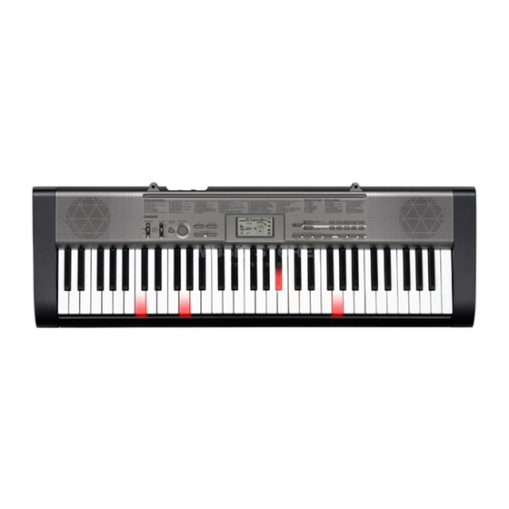
Casio LK-125 Service Manual & Parts Manual
Hide thumbs
Also See for LK-125:
- User manual (68 pages) ,
- User manual (37 pages) ,
- User manual (37 pages)
Table of Contents
Advertisement
Quick Links
Advertisement
Table of Contents

Related Manuals for Casio LK-125


Summary of Contents for Casio LK-125
- Page 1 LK-125 SEP. 2010 LK-125 ELECTRONIC KEYBOARD Ver. 2 : Jan. 2012...
-
Page 2: Table Of Contents
LK-125 CONTENTS SPECIFICATIONS ................... 1 BLOCK AND WIRING DIAGRAM ..............2 PCB INFORMATION ..................3 CIRCUIT DESCRIPTION ................4 PRINTED CIRCUIT BOARDS ................. 5 DISASSEMBLY ....................7 DIAGNOSTIC PROGRAM ................16 EXPLODED VIEW ..................22 PARTS LIST ....................23 SCHEMATIC DIAGRAMS ................26... -
Page 3: Specifications
Auto-accompaniment Rhythm Patterns 50 presets Tempo Adjustable, (216 steps, = 40 to 255), initial value; 120 Chords Two systems; CASIO CHORD, FINGERED Other Fill-in pattern, Synchro start Song Bank Tunes 100 tunes Musical Information Function Tone, Auto Accompaniment, Song Bank numbers and names; tempo,... -
Page 4: Block And Wiring Diagram
LK-125 BLOCK AND WIRING DIAGRAM KEYBOARD LED PCB KEYBOARD LED PCB KEYBOARD LED PCB (CSM446-LD5M) (CSM446-LD4M) (CSM446-LD3M) KEYBOARD PCB JE (6 pin) JF (6 pin) JG (6 pin) (M800-KYA1) CN801 (13 pin) CN505 (6 pin) CN504 (6 pin) CN504 (6 pin) -
Page 5: Pcb Information
LK-125 PCB INFORMATION M800-KYA1 M820-PSA1 M821-MDA1 M800-KYA2 CSM446-LD3 CSM446-LD4 CSM446-LD5 M821-LDA1 M821-LDA2 Classifi cation Parts Name PCB Name Components MPU, LCD Controller, Keyboard LED Main PCB PCB ASSY/MDA1 M821-MDA1 Controller, Reset IC, Buttons, Right Speaker Terminal Power Supply Circuit, Power Amplifi er,... -
Page 6: Circuit Description
LK-125 CIRCUIT DESCRIPTION KEY MATRIX „ „ NOMENCLATURE OF KEYS „ „ BUTTON MATRIX „ „ KO8S KO9S KO10S KO11S KI0S TONE STEP 1 KI1S RHYTHM STEP 2 KI2S SONG BANK STEP 3 KI3S PART SELECT SPEAK ONE KEY PLAY... -
Page 7: Printed Circuit Boards
LK-125 PRINTED CIRCUIT BOARDS Main PCB: M821-MDA1 Power Amp PCB: M820-PSA1 – 5 –... - Page 8 LK-125 Keyboard LED PCB: M821-LDA1 Keyboard LED PCB: M821-LDA1 Keyboard PCB: M800-KYA1 Keyboard PCB: M800-KYA2 – 6 –...
-
Page 9: Disassembly
LK-125 DISASSEMBLY CAUTION „ „ The photos show a prototype. The appearance of the instrument, such as color, may „ differ from the actual model. To avoid damages to the instrument and the floor, lay the instrument on a mattress „... - Page 10 LK-125 DISASSEMBLY „ „ PANEL UNIT A-1. Undo 11 screws on the bottom surface of the main unit A-2. When replacing the keyboard LED PCBs, undo 16 screws and then remove the L-COVER-A/B/C. L-COVER-C L-COVER-B L-COVER-A <Caution for installing L-COVER-A/B/C>...
- Page 11 LK-125 A-3. Turn over the panel unit. A-4. Unsolder two battery lead wires. A-5. Unsolder two FFCs. Lead wire (Red) Lead wire (Black) FFC (M800-KYA2) FFC (M821-LDA2) A-6. Remove the panel unit. M820-PSA1 PCB M821-MDA1 PCB – 9 –...
- Page 12 LK-125 MAIN PCB (M821-MDA1) B-1. Unsolder two FFCs. FFC (M800-KYA2) FFC (M821-LDA2) B-2. Unsolder two lead wires and one FFC. Lead wire (White) Lead wire (Blue) FFC (M820-PSA1) B-3. Unsolder two lead wires connected to the right speaker. Lead wire (White) Lead wire (Blue) –...
- Page 13 LK-125 B-4. Undo 16 screws and then remove the M821-MDA1 PCB, rubber keys and LCD. Rubber keys <Caution for installing M821-MDA1 PCB> To install the M821-MDA1 PCB, tighten the screws for the LCD part in the order shown in the right.
- Page 14 LK-125 POWER AMP PCB (M820-PSA1) C-1. Unsolder two lead wires and one FFC connected to the M821-MDA1 PCB. Lead wire (White) Lead wire (Blue) FFC (M820-PSA1) C-2. Unsolder two lead wires connected to the left speaker. Lead wire (Blue) Lead wire (White) C-3.
- Page 15 LK-125 KEYBOARD D-1. Undo eight screws and then remove the side panels. Left side panel Right side panel D-2. Undo 21 screws and then remove the white keys and black keys. – 13 –...
- Page 16 LK-125 KEYBOARD PCB (M800-KYA1/KYA2) E-1. Disengage the hooks and then remove the M800-KYA1/KYA2 PCBs. E-2. Remove five rubber contact strips. NOTE: One rubber contact strip differs in length. Rubber contact strips This rubber contact strip differs from the others in length.
- Page 17 LK-125 KEYBOARD LED PCB (M821-LDA1/LDA2, CSM446-LD3M/LD4M/LD5M) CSM446-LD3M PCB CSM446-LD4M PCB CSM446-LD5M PCB M821-LDA1 PCB M821-LDA2 PCB F-1. Undo 14 screws on the M821-LDA1/LDA2 PCBs. F-2. Turn over the M821-LDA1/LDA2 PCBs. NOTE: Do not touch the LEDs. F-3. Unsolder three FFCs and then remove the M821-LDA1/LDA2 PCBs.
-
Page 18: Diagnostic Program
LK-125 DIAGNOSTIC PROGRAM INITIAL SETTING „ „ Connect the AC adaptor. Turn the volume to the maximum. HOW TO START THE DIAGNOSTIC PROGRAM „ „ Hold down the “0” and “START/STOP” buttons at the same time, to turn the power ON. - Page 19 LK-125 DIAGNOSTIC PROGRAM „ „ MODE SWITCH CHECK A-1. Switch the mode switch and check that the following screen appears on the LCD. Mode Switch FINGERED CASIO CHORD NORMAL – 17 –...
- Page 20 LK-125 BUTTON CHECK B-1. Press the “0” button to select the “Button Check”. B-2. Press the keys in the order of the numbers indicated in the illustration below. If the button function is OK: The confirmation chord sounds, and the button number and “OK” appear on the LCD.
- Page 21 LK-125 KEYBOARD LED CHECK D-1. Press the “TONE” button to perform the “LED Check”. Automatically the keyboard LEDs are lit. Check the following points. • The confirmation chords sound and the LEDs are lit in the order indicated in the illustration below.
- Page 22 LK-125 E-3. Press the “STEP 3” button. The LCD displays automatically change with the confirmation chords in the order indicated in the illustration below. AUTO POWER OFF CHECK F-1. Press the “PART SELECT” button to perform the “Auto Power Off Check”.
- Page 23 LK-125 KEY CHECK NOTE: Perform the tests with regular power-on state. G-1. Check the following points by pressing all keys. • The tones sound correctly by hitting keys. • The pitch of the sound corresponding to a key is correct.
-
Page 24: Exploded View
LK-125 EXPLODED VIEW – 22 –... -
Page 25: Parts List
PARTS LIST LK-125 Notes: 1. Prices and specifications are subject to change without prior notice. 2. Refer to the latest “Parts Price Code” at “PARTS FINDER” on the Casio Service WEB site (https://www.servicecasio.com). 3. As for spare parts order and supply, refer to the “GUIDEBOOK for Spare parts Supply”, published separately. 4. The numbers in item column correspond to the same numbers in drawing. – 23 –... - Page 26 LK-125 1: LK-125_DI 2: LK-125_EU 3: LK-125_UK 4: LK-125_US Q'ty Price Item Code No. Parts Name Specification Remarks Code MAIN PCB 10368210 PCB ASSY/MDA1 TK-RJM510419*001 B MDA1 PCB 10178633 WIRE/for speaker 1007TASC24100B4040 X Blue (+) 10366747 WIRE/for speaker 1007TASC24100W4040 X White (-)
- Page 27 LK-125 1: LK-125_DI 2: LK-125_EU 3: LK-125_UK 4: LK-125_US Q'ty Price Item Code No. Parts Name Specification Remarks Code PANEL UNIT 10371166 PLATE/DISPLAY RJM510316-003V02 10301435 KNOB RJM503803-009V01 69095890 CONTACT/SLIDE SWITCH CSB-12D 10417026 FABRIC TAPE RJM511849-001V01 10417025 FABRIC TAPE RJM511833-001V01 10272509...
-
Page 28: Schematic Diagrams
LK-125 SCHEMATIC DIAGRAMS Main PCB: M821-MDA1 (to PSA1CN201) (to LDA2/CN506) (to KYA2/CN803) RIGHT SPEAKER (to PSA1/CN206) : Not used (to RIGHT SPEAKER) (to PSA1/CN207) – 26 –... - Page 29 LK-125 Power Amp PCB: M820-PSA1 LEFT SPEAKER BATTERY DC 9 V IN (to BATTERY) PHONES/OUTPUT (J201) (J202) (to MDA1/CN6) (to MDA1/CN7) (to LEFT SPEAKER) (to MDA1/CN3) POWER/MODE SWITCH (SW201) (to KYA2/CN803) VOLUME (SW202) : Not used – 27 –...
- Page 30 LK-125 Keyboard LED PCB: M821-LDA1 (to LD3M/JG) (to LDA2/CN503) – 28 –...
- Page 31 LK-125 Keyboard LED PCB: M821-LDA2 (to LDA1/CN501) (to LD4M/JF) (to LD5M/JE) (to MDA1/CN2) – 29 –...
- Page 32 LK-125 Keyboard LED PCB: CSM446-LD3M/LD4M/LD5M (to LDA1/CN502) (to LDA2/CN504) (to LDA2/CN505) – 30 –...
- Page 33 LK-125 Keyboard PCB: M800-KYA1/KYA2 : Not used (to KYA1/ (to MDA1/ CN801) CN1) : Not used (to KYA2/ CN802) – 31 –...
- Page 34 • Correction of the PARTS LIST (P24) Ver. 2 : Jan. 2012 • Correction of the EXPLODED VIEW (P22) • Correction of the PARTS LIST (P24 and P25) CASIO COMPUTER CO.,LTD. Overseas Service Division 6-2, Hon-machi 1-Chome Shibuya-ku, Tokyo 151-8543, Japan...