Advertisement
Quick Links
User's Guide
1.0
Introduction
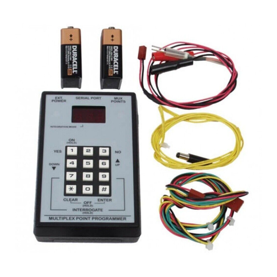
Use the multiplex point programmer (Figure 1 and
Table 1) to program multiplex bus points for the Bosch
Security Systems D9412G, D9412, D9112, D7412G,
D7412, D7212G, and D7212 Control Panels. In
addition to programming points, the D5060 can also
be used to program and read information from a
D8125MUX.
Figure 1: Multiplex Point Programmer
EXT.
SERIAL PORT
POWER
INTERROGATION MODE
ON
(HOLD)
YES
1
4
DOWN
7
*
CLEAR
INTERROGATE
MULTIPLEX POINT PROGRAMMER
Table 1: D5060 LED Display Definitions
Display
Definition
Adr
Enter address
A.dr
Enter address for Interrogation Mode
bAd
Battery voltage is below 15 V
Err
Point was not programmed correctly
Lob
Battery voltage is below 16 V
noP
No response from point
PnL
Communications with the D8125 failed
rSP
Point responds to address
tYP
Enter point type
t.YP
Enter point type for Interrogation Mode
Multiplex Point Programmer D5060
MUX
POINTS
NO
2
3
5
6
UP
9
8
0
#
ENTER
OFF
(HOLD)
(HOLD)
2.0
Installation
1. If using external power, attach the flying leads of
the included power cable to the output terminals
of a 16.5 VAC transformer. Insert the plug end
into the jack labeled EXT. POWER on the
programmer. Refer to Figure 2, Figure 3, and
Figure 4.
2. For control panels, use the serial cable provided
to connect the D8125MUX to the D9412G,
D9412, D9112, D7412G, D7412, D7212G, or
D7212 Control Panel to the jack labeled SERIAL
PORT on the programmer.
3. For MUX devices without DIP switches, use the
multiplex programmer cable provided to connect
the point to be programmed to the port labeled
MUX POINTS as shown in Figure 2. Use the
appropriate connector, either the alligator clips or
the probes, to connect the programmer to a point.
For MUX devices with DIP switches, program
the point using the DIP switches. Connect the
programmer to the D8125 MUX as shown in
Figure 3, using the C318 serial cable (Figure 4) to
program the point number and point type into
the D8125MUX.
Figure 2: Wiring Diagram When Installing MUX
Points Without DIP Switches
1
RESE T
12V
IN
OUT
GND
ZONEX BUS
EXT.
POWER
INTERROGATION MODE
1 - External power
2 - D8125 MUX
3 - MUX point without DIP switches (non-i
models)
4 - D5060 Multiplex Point Programmer
May 2004
3
2
FIRE MANUA L
PROG
+
-
+
-
+
-
+
-
PORT
WALK TES T
POWER A
MU X B US A
POWER B
M UX BUS B
SERIAL PORT
MUX
POINTS
4
Advertisement

Related Manuals for Bosch D5060

Summary of Contents for Bosch D5060
- Page 1 Use the multiplex point programmer (Figure 1 and 1. If using external power, attach the flying leads of Table 1) to program multiplex bus points for the Bosch the included power cable to the output terminals Security Systems D9412G, D9412, D9112, D7412G, of a 16.5 VAC transformer.
- Page 2 D5060 to program MUX Powering the D5060 points with programming DIP switches. To turn the D5060 on, press and hold the [1] key until the unit beeps. To turn the unit off, press and hold the Figure 3: Wiring Diagram When Installing MUX [#] and [*] keys simultaneously until the unit beeps.
- Page 3 MODE lights. D8125MUX 2. The display reads A.dr and the left-most decimal 1. Apply power to the D5060 and connect the point lights, prompting you to enter a starting programmer to the D8125MUX only. address. Enter an address and press [#].
- Page 4 To preserve the life of the batteries, requirements of the unit. remove them from the multiplex point programmer whenever you will not use the unit for any length of time. © Bosch Security Systems B.V., 2021 F01U034899-02 2021.07 Torenallee 49 5617 BA Eindhoven, Netherlands User's Guide...