
Summary of Contents for R9 Technology SN400
- Page 1 User Guide SN400 Sensor Node Hardware User Guide January 2021 Release 1.7 R9 Technology 17217 Waterview Parkway Suite 1.202Y Dallas, TX 75252 www.r9technology.com Copyright © 2021 R9 Technology Inc. All rights reserved.
- Page 2 Edit to pair button led flash info, other minor edits 01/11/2021 R1.5 Change DC adapter voltage to 3.0V, other minor edits. 01/21/2021 R1.6 Updated battery information 03/26/2021 R1.7 Updated battery information Copyright © 2021 R9 Technology Inc. All rights reserved.
-
Page 3: Table Of Contents
Indicators and Buttons ............................9 Physical Dimensions ............................. 11 Installation ................................11 Troubleshooting ..............................13 Sales and Warranty Policy ..........................13 Specifications ................................14 Certifications - United States FCC Statement ..................... 15 Copyright © 2021 R9 Technology Inc. All rights reserved. -
Page 4: Introduction
The SN400 device’s position in the overall network can be seen in the diagram below. The SN400 “Piconode” device is at the far-right end of the network diagram. It gathers sensor information using wired sensors, which will, ultimately, be viewed and analyzed on a user’s personal computer or smart device using a web-browser. -
Page 5: Sn400 Product Label
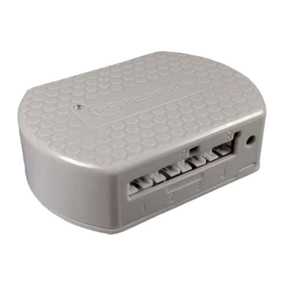
2 SN400 Product Label The SN400 product label located on the side of the device will indicate several important features of the device. Copyright © 2021 R9 Technology Inc. All rights reserved. - Page 6 1. The MAC ID, circled in red, in the picture below is unique to a specific SN400 device. The last 5 digits of the MAC ID will be entered into the online portal system during setup, and is used to identify the SN400 in the system. The last 5 digits of the serial number is also entered.
-
Page 7: Wireless Operating Band (Antenna)
The SN400 915 MHz. antenna is PCB mounted and located internally to the enclosure. Note that it is possible to connect an external antenna to the SN400 device. This is supported only as an option, and should not be necessary in a typical application. - Page 8 Batteries are not supplied with the sensor node, and should be inserted by the customer at the time of SN400 installation. If the sensor node device is not to be used for a long period of time, the batteries should be removed to prevent their depletion.
-
Page 9: Indicators And Buttons
(P) will indicate the network pairing status (to gateway) using the LED indicator. Long pressing the pairing button will cause the SN400 to clear its paired status to a gateway, and it will start broadcasting to initiate a new connection to a nearby gateway. - Page 10 SN400 LED indication - power on and reset button quick press Color Blink Description Count Red/Green fast 6 The SN400 LED will illuminate with a quick flicker of both red and green colors on the LED. The SN400 sensor node is initialized, but the gateway pairing information is not erased.
-
Page 11: Physical Dimensions
All dimensions are shown in millimeters. 7 Installation To facilitate mounting, the SN400 is provided with two rear facing magnets for easy attachment to a ferrous metal, steel surface. Alternatively, a fastener screw, or double- sided adhesive foam tape can be used on the top flange for mounting to a wall or other flat surface. - Page 12 Ideally, the external ports should point downward to prevent ingress of spills and liquids. The image below shows the SN400 installed on the outside of a refrigerator using integrated magnets. An external wired sensor is used to sense refrigerator temperature.
-
Page 13: Troubleshooting
8 Troubleshooting The table below indicates common issues and resolutions for the SN400 sensor node. Symptom Issue Resolution Reset button works AAA batteries are low. When Replace AAA batteries. properly, but pairing button batteries are low, there is does not work. SN400 will typically enough energy to not connect to portal. -
Page 14: Specifications
DC jack for external power input (0.65 mm, 3.0V) -20°C to 45°C device temperature operating range (with batteries on module) Optional external antenna can be configured Optional external DC power supply Copyright © 2021 R9 Technology Inc. All rights reserved. -
Page 15: Certifications - United States Fcc Statement
This equipment should be installed and operated with a minimum distance of 20cm between the radiator and all persons. This transmitter must not be co-located or operating in conjunction with any other antenna or transmitter. Copyright © 2021 R9 Technology Inc. All rights reserved.