Table of Contents
Advertisement
Quick Links
Advertisement
Table of Contents

Related Manuals for Data Translation DT9816


Summary of Contents for Data Translation DT9816
- Page 1 Title Page UM-21336-M DT9816 User’s Manual...
- Page 2 Information furnished by Data Translation, Inc. is believed to be accurate and reliable; however, no responsibility is assumed by Data Translation, Inc. for its use; nor for any infringements of patents or other rights of third parties which may result from its use.
- Page 3 Changes or modifications to this equipment not expressly approved by Data Translation could void your authority to operate the equipment under Part 15 of the FCC Rules.
-
Page 5: Table Of Contents
Table of Contents Table of Contents About this Manual ............9 Intended Audience. - Page 6 Contents Part 2: Using Your Module........45 Chapter 5: Principles of Operation .
- Page 7 Contents Clocks ............... 66 Counter/Timers .
- Page 8 Contents...
-
Page 9: About This Manual
About this Manual The first part of this manual describes how to install and set up your DT9816 module and software, and verify that your module is working properly. The second part of this manual describes the features of the DT9816 module and device driver, and how to program the DT9816 module using the DT-Open Layers for .NET Class... -
Page 10: Conventions Used In This Manual
Refer to the following documents for more information on using the DT9816 module: • Benefits of the Universal Serial Bus for Data Acquisition. This white paper describes why USB is an attractive alternative for data acquisition. It is available on the Data Translation web site (www.datatranslation.com). -
Page 11: Where To Get Help
• Microsoft Windows XP, Windows Vista, or Windows 7 documentation. • USB web site (http://www.usb.org). Where To Get Help Should you run into problems installing or using a DT9816 module, the Data Translation Technical Support Department is available to provide technical assistance. Refer to Chapter 7 for more information. - Page 12 About this Manual...
-
Page 13: Chapter 1: Overview
Overview Key Hardware Features............Supported Software . -
Page 14: Key Hardware Features
• Six, independent, successive-approximation A/D converters with track-and-hold circuitry. Each converter uses a common clock and trigger for simultaneous sampling of all six analog input signals at up to 50 kHz per channel (DT9816), 150 kHz per channel (DT9816-A), or 750 kHz per channel (DT9816-S). -
Page 15: Supported Software
The following software is available for use with the DT9816 module, and is provided on the OMNI CD: • Device Driver – The DT9816 Device Driver allows you to use a DT9816 module with any of the supported software packages or utilities. Refer to... -
Page 16: Getting Started Procedure
Figure 1 illustrates the steps needed to get started using the DT9816 module. This diagram is repeated in each chapter; the shaded area in the diagram shows you where you are in the getting started procedure. Set Up and Install the Module... -
Page 17: Part 1: Getting Started
Part 1: Getting Started... -
Page 19: Chapter 2: Setting Up And Installing The Module
Setting Up and Installing the Module Unpacking ..............Attaching Modules to the Computer. - Page 20 Chapter 2 Set Up and Install the Module (this chapter) Wire Signals to the Module (see Chapter 3 starting on page Verify the Operation of the Module (see Chapter 4 starting on page...
-
Page 21: Unpacking
• OMNI CD • USB cable If an item is missing or damaged, contact Data Translation. If you are in the United States, call the Customer Service Department at (508) 481-3700, ext. 1323. An application engineer will guide you through the appropriate steps for replacing missing or damaged items. If you are located outside the United States, call your local distributor (see Data Translation’s web site... -
Page 22: Attaching Modules To The Computer
Note: Most computers have several USB ports that allow direct connection to USB devices. If your application requires more DT9816 modules than you have USB ports for, you can expand the number of USB devices attached to a single USB port by using expansion hubs. -
Page 23: Connecting To An Expansion Hub
Connecting to an Expansion Hub Expansion hubs are powered by their own external power supply. The practical number of DT9816 modules that you can connect to a single USB port depends on the throughput you want to achieve. To connect multiple DT9816 modules to an expansion hub, do the following: 1. - Page 24 The operating system automatically detects the USB devices as they are installed. DT9816 Module DT9816 Module USB Cables Host Computer USB Cable USB Cable Power Supply Expansion Hubs for Hub Power Supply for Hub DT9816 Module DT9816 Module USB Cables Figure 3: Attaching Multiple DT9816 Modules Using Expansion Hubs...
-
Page 25: Changing The Name Of A Module (Optional)
2. From the Control Panel, double-click Open Layers Control Panel. The Data Acquisition Control Panel dialog box appears. 3. If you want to rename the module, click the DT9816 module that you want to rename, and then click Edit Name. - Page 26 Chapter 2...
-
Page 27: Chapter 3: Wiring Signals To The Module
Wiring Signals to the Module Preparing to Wire Signals ............Connecting Single-Ended Analog Input Signals . - Page 28 Chapter 3 Set Up and Install the Module (see Chapter 2 starting on page Wire Signals to the Module (this chapter) Verify the Operation of the Module (see Chapter 4 starting on page...
-
Page 29: Preparing To Wire Signals
• Prevent electrostatic discharge to the I/O while the box is operational. • Connect all unused analog input channels to analog ground. Wiring Locations You wire signals to the DT9816 module using the screw terminals on the module. Table 2 lists the screw terminal assignments. -
Page 30: Connecting Single-Ended Analog Input Signals
Analog In 1 source DT9816 Module source 0 Analog In 0 Signal Source Figure 4: Connecting Single-Ended Inputs Note: When using high sampling rates on the DT9816-S, it is recommended that you use an input impedance of 100 Ω or less. -
Page 31: Connecting Digital I/O Signals
Wiring Signals to the Module Connecting Digital I/O Signals Figure 5 shows how to connect digital input signals (lines 0 and 1, in this case) to the screw terminals of a DT9816 module. Ground Digital Input 1 Digital Input 0... -
Page 32: Connecting Counter/Timer Signals
Chapter 3 Connecting Counter/Timer Signals The DT9816 module provides one counter/timer that you can use for the following operations: • Event counting • Frequency measurement • Continuous pulse output (rate generation) This section describes how to connect counter/timer signals for these operation modes. Refer page 55 for more information about using the counter/timers. -
Page 33: Connecting Signals For Frequency Measurement
Ground Signal Source Counter 0 In DT9816 Module Figure 8: Connecting Counter/Timer Signals for an Event Counting Operation Without Using a Gate Connecting Signals for Frequency Measurement One way to measure frequency is to connect a pulse of a known duration to the Counter 0... -
Page 34: Connecting Signals For Rate Generation
Chapter 3 Connecting Signals for Rate Generation Figure 10 shows how to connect counter/timer signals to the screw terminals of a DT9816 module to perform a rate generation (continuous pulse output) operation. Ground Heater Controller Counter 0 Out DT9816 Module... -
Page 35: Chapter 4: Verifying The Operation Of A Module
Verifying the Operation of a Module Running the Quick DataAcq Application......... Testing Single-Value Analog Input . - Page 36 Chapter 4 Set Up and Install the Module (see Chapter 2 starting on page Wire Signals to the Module (see Chapter 3 starting on page Verify the Operation of the Module (this chapter)
-
Page 37: Running The Quick Dataacq Application
For information on each of the features provided, use the online help for the Quick DataAcq application by pressing F1 from any view or selecting the Help menu. If the system has trouble finding the help file, navigate to C:\Program Files\Data Translation\Win32\ dtdataacq.hlp, where C: is the letter of your hard disk drive. -
Page 38: Testing Single-Value Analog Input
2. In the Quick DataAcq application, choose Single Analog Input from the Acquisition menu. 3. Select the appropriate DT9816 module from the Board list box. 4. In the Channel list box, select analog input channel 0. 5. In the Range list box, select the range for the channel (±10 V). -
Page 39: Testing Continuous Analog Input
To verify that the module can perform a continuous analog input operation, do the following: 1. Connect known voltage sources, such as the outputs of a function generator, to analog input channels 0 and 1 on the DT9816 module (using the single-ended configuration). Refer to page 30 for an example of how to connect a single-ended analog input. -
Page 40: Testing Single-Value Digital Input
Testing Single-Value Digital Input To verify that the module can read a single digital input value, do the following: 1. Connect a digital input to digital input line 0 of port A on the DT9816 module. Refer to page 31 for an example of how to connect a digital input. -
Page 41: Testing Single-Value Digital Output
Testing Single-Value Digital Output To verify that the module can output a single digital output value, do the following: 1. Connect a digital output to digital output line 0 of port B on the DT9816 module. Refer to page 31 for an example of how to connect a digital output. -
Page 42: Testing Frequency Measurement
Testing Frequency Measurement To verify that the module can perform a frequency measurement operation, do the following: 1. Wire an external clock source to counter/timer 0 on the DT9816 module. Refer to page 33 for an example of how to connect signals to a counter/timer for a frequency measurement operation. -
Page 43: Testing Pulse Output
Verifying the Operation of a Module Testing Pulse Output To verify that the module can perform a pulse output operation, do the following: 1. Connect a scope to counter/timer 0 on the DT9816 module. Refer to page 34 for an example of how to connect a scope (a pulse output) to counter/timer 0. - Page 44 Chapter 4...
-
Page 45: Part 2: Using Your Module
Part 2: Using Your Module... -
Page 47: Chapter 5: Principles Of Operation
Principles of Operation Analog Input Features ............Digital I/O Features. - Page 48 Chapter 5 Figure 11 shows a block diagram of the DT9816 module. +2.5 V Power +5 V Reference Supply From USB Port C/T Out 0 16-Bit A/D Ch5 C/T Gate 0 Counter/Timer C/T In 0 A/D Ch4 A/D Ch3 DOUT 7...
-
Page 49: Analog Input Features
• Error conditions, described on page 53 Input Resolution The resolution of the A/D subsystem on the DT9816 module is 16-bits. This resolution is fixed; it cannot be programmed in software. Analog Input Channels The DT9816 provides six single-ended simultaneous analog input channels. You can acquire data from a single analog input channel or from a group of analog input channels on the module. -
Page 50: Specifying One Or More Analog Input Channels
Input Ranges and Gains The DT9816 provides an input range of ±10 V. Use software to specify the range as ±10 V with a gain of 1, or ±10 V with a gain of 2 for an effective input range of ±5 V. -
Page 51: Analog Input Conversion Modes
Principles of Operation Analog Input Conversion Modes The DT9816 supports the following conversion modes: • Single-value operations • Continuous scan operations The following subsections describes the conversion modes in more detail. Single-Value Operations Single-value operations are the simplest to use. Using software, you specify the range, gain, and analog input channel. -
Page 52: Input Triggers
(TTL) trigger. Data Format and Transfer DT9816 modules use binary data encoding, where 0000 represents negative full-scale, and FFFFh represents positive full-scale. Use software to specify the data encoding as binary. The ADC outputs FFFFh for above-range signals, and 0000 for below-range signals. -
Page 53: Error Conditions
Principles of Operation Error Conditions An overrun condition is reported if the A/D sample clock rate is too fast. This error is reported if a new A/D sample clock pulse occurs while the ADC is busy performing a conversion from the previous A/D sample clock pulse. The host computer can clear this error. To avoid this error, use a slower sampling rate or increase the buffer size and/or number of buffers. -
Page 54: Digital I/O Features
The DT9816 supports single-value digital I/O operations only. For a single-value operation, use software to specify the digital I/O port (the gain is ignored). The DT9816 then reads data from or writes data to the digital lines associated with that port. -
Page 55: Counter/Timer Features
Principles of Operation Counter/Timer Features This section describes the following features of counter/timer (C/T) operations on the DT9816 module: • C/T channel, described below • C/T clock sources, described on page 56 • Gate types, described on page 56 • Pulse types and duty cycles, described on page 56 •... -
Page 56: C/T Clock Sources
The duty cycle (or pulse width) indicates the percentage of the total pulse output period that is active. In rate generation mode, the duty cycle is fixed at 50% for the DT9816 module. Figure illustrates a high-to-low going output pulse with a duty cycle of 50%. -
Page 57: Counter/Timer Operation Modes
Active Pulse Width Figure 14: Example of a Pulse Output SIgnal with a 50% Duty Cycle (High-to-Low Going) Counter/Timer Operation Modes The DT9816 module supports the following counter/timer operation modes: • Event counting • Frequency measurement • Rate generation Event Counting Use event counting mode if you want to count the number of falling edges that occur on Counter 0 In when the gate is active (high-level). -
Page 58: Rate Generation
Chapter 5 Make sure that the signals are wired appropriately. Refer to page 33 for an example of connecting a frequency measurement application. Rate Generation Use rate generation mode to generate a continuous pulse output signal from Counter 0 Out; this mode is sometimes referred to as continuous pulse output or pulse train output. -
Page 59: Chapter 6: Supported Device Driver Capabilities
Supported Device Driver Capabilities Data Flow and Operation Options..........Buffering . - Page 60 The tables in this chapter summarize the features available for use with the DT-Open Layers for .NET Class Library and the DT9816 modules. The DT-Open Layers for .NET Class Library provides properties that return support information for specified subsystem capabilities.
-
Page 61: Data Flow And Operation Options
Supported Device Driver Capabilities Data Flow and Operation Options Table 5: DT9816 Data Flow and Operation Options DT9816 DOUT QUAD Single-Value Operation Support SupportsSingleValue Simultaneous Single-Value Output Operations SupportsSetSingleValues Continuous Operation Support SupportsContinuous Continuous Operation until Trigger SupportsContinuousPreTrigger Continuous Operation before & after Trigger... -
Page 62: Buffering
QUAD Buffer Support SupportsBuffering Single Buffer Wrap Mode Support SupportsWrapSingle Inprocess Buffer Flush Support SupportsInProcessFlush Triggered Scan Mode Table 7: DT9816 Triggered Scan Mode Options DT9816 DOUT QUAD Triggered Scan Support SupportsTriggeredScan Maximum Number of CGL Scans per Trigger MaxMultiScanCount... -
Page 63: Channels
Channel-List Inhibit SupportsChannelListInhibit a. The DT9816 provides analog input channels 0 to 5. b. You cannot specify the same channel more than once in the list. Place channels in your channel list in ascending order. All channels are sampled simultaneously with data returned in ascending channel order;... -
Page 64: Ranges
Chapter 6 Ranges Table 11: DT9816 Range Options DT9816 DOUT QUAD Number of Voltage Ranges NumberOfRanges Available Ranges SupportedVoltageRanges ±10 V Current Output Support SupportsCurrentOutput Resolution Table 12: DT9816 Resolution Options DT9816 DOUT QUAD Software Programmable Resolution SupportsSoftwareResolution Number of Resolutions... -
Page 65: Thermocouple And Rtd Support
Supported Device Driver Capabilities Thermocouple and RTD Support Table 13: DT9816 Thermocouple and RTD Support Options DT9816 DOUT C/T QUAD Thermocouple Support SupportsThernocouple RTD Support SupportsRTD Resistance Support ReturnsOhms Voltage Converted to Temperature in Hardware SupportsTemperatureDataInStream Supported Thermocouple Types ThermocoupleType... -
Page 66: Triggers
The DT9816 supports an actual maximum of 50 kHz, the DT9816-A supports an actual maximum of 153.846 kHz, and the DT9816-S supports an actual maximum of 750 kHz. c. For the DT9816 and DT9816-A, the actual minimum is 61 Hz. For the DT9816-S, the minimum frequency is 183.1 Hz. -
Page 67: Counter/Timers
Supported Device Driver Capabilities Counter/Timers Table 17: DT9816 Counter/Timer Options DT9816 DOUT QUAD Cascading Support SupportsCascading Event Count Mode Support SupportsCount Generate Rate Mode Support SupportsRateGenerate One-Shot Mode Support SupportsOneShot Repetitive One-Shot Mode Support SupportsOneShotRepeat Up/Down Counting Mode Support SupportsUpDown... - Page 68 Chapter 6 Table 17: DT9816 Counter/Timer Options (cont.) DT9816 DOUT QUAD Gate-Rising Edge Type SupportsGateRising Interrupt-Driven Operations SupportsInterrupt a. The pulse width (duty cycle) if fixed at 50% when rate generation mode is used.
-
Page 69: Chapter 7: Troubleshooting
Troubleshooting General Checklist ............. Technical Support . -
Page 70: General Checklist
7. Search the DT Knowledgebase in the Support section of the Data Translation web site (at www.datatranslation.com) for an answer to your problem. 8. Visit the product’s page on the Data Translation web site for the latest tips, white papers, product documentation, and software fixes. - Page 71 Chapter The DT9816 module is out of The DT9816 module is calibrated at the factory and calibration. should not require recalibration. If you want to readjust the calibration of the analog input or analog output circuitry, refer to the instructions on the Data Translation web site (www.datatranslation.com).
-
Page 72: Technical Support
Chapter 7 Technical Support If you have difficulty using a DT9816 module, Data Translation’s Technical Support Department is available to provide technical assistance. To request technical support, go to our web site at http://www.datatranslation.com and click on the Support link. -
Page 73: If Your Module Needs Factory Service
If you are located outside the USA, call your local distributor for authorization and shipping instructions. The name and telephone number of your nearest distributor are listed on Data Translation’s web site. All return shipments to Data Translation must be marked with the correct RMA number to ensure proper processing. - Page 74 Chapter 7...
-
Page 75: Appendix A: Specifications
Specifications Analog Input Specifications ........... . Digital I/O Specifications . -
Page 76: Analog Input Specifications
Appendix A Analog Input Specifications Table 19 lists the specifications for the A/D subsystem on the DT9816 module. Table 19: A/D Subsystem Specifications Feature DT9816 Specifications Number of analog input channels 6 single-ended Number of gains 2 (1, 2) Resolution... - Page 77 8 kV Contact: 4 kV Reference 2.5 V Monotonicity a. Very high input impedance minimizes any source error. When using high sampling rates on Ω the DT9816-S, it is recommended that you use an input impedance of 100 or less.
-
Page 78: Digital I/O Specifications
Appendix A Digital I/O Specifications Table 20 lists the specifications for the digital input (DIN) and digital output (DOUT) subsystems on the DT9816 module. Table 20: DIN/DOUT Subsystem Specifications Feature DT9816 Specifications Number of digital I/O lines 16 (8 each; dedicated) -
Page 79: Counter/Timer Specifications
Specifications Counter/Timer Specifications Table 21 lists the specifications for the C/T subsystem on the DT9816 module. Table 21: C/T Subsystem Specifications Feature Specifications Number of counter/timers Counter/timer modes Event counting, frequency measurement, rate generation Resolution 16-bit Minimum pulse width: 25 ns... -
Page 80: Power, Physical, And Environmental Specifications
Appendix A Power, Physical, and Environmental Specifications Table 22 lists the power, physical, and environmental specifications for the DT9816 module. Table 22: Power, Physical, and Environmental Specifications Feature DT9816 Specifications Power, +5 V Enumeration < 100 mA Operation < 250 mA... -
Page 81: Regulatory Specifications
Specifications Regulatory Specifications Table 23 lists the regulatory specifications for the DT9816 module. Table 23: Regulatory Specifications Feature Specifications Emissions (EMI) FCC Part 15, EN55022:1994 + A1:1995 + A2:1997 VCCI, AS/NZS 3548 Class A Immunity EN61000-6-1:2001 RoHS (EU Directive 2002/95/EG) - Page 82 Appendix A...
-
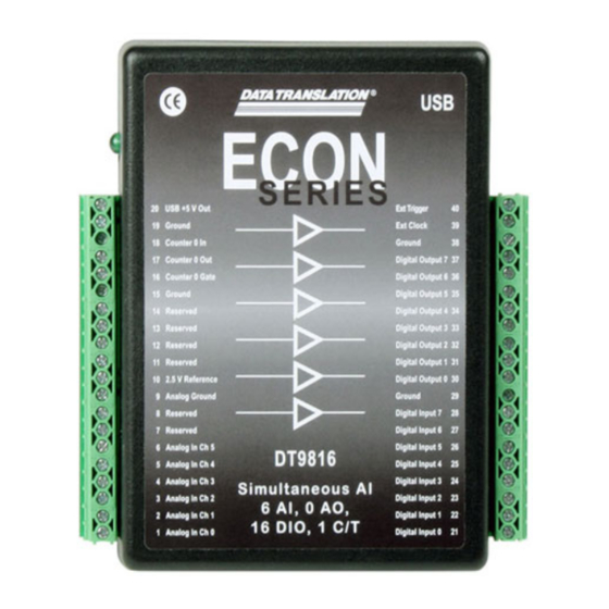
Page 83: Appendix B: Screw Terminal Assignments
Screw Terminal Assignments... - Page 84 Appendix B Table 24 lists the screw terminal assignments for the DT9816 module. Table 24: DT9816 Screw Terminal Assignments Screw Screw Terminal Signal Terminal Signal USB +5 V Out Ext Trigger Ground Ext Clock Counter 0 In Ground Counter 0 Out...
-
Page 85: Index
Index Index channel type differential A/D subsystem specifications single-ended aliasing channel-gain list analog input depth channel-gain list for analog input channels for analog input channels channels channels conversion modes analog input data format and transfer counter/timer error conditions digital I/O gain number of ranges... - Page 86 Index event counting gate types factory service high-level gate type features high-to-low output pulse formatting data, analog input internal gate type frequency interrupt-driven operations base clock rate generation mode internal A/D clock subsystem specifications internal A/D sample clock variable pulse width internal C/T clock counting events internal retrigger clock...
- Page 87 Index testing types MATLAB wiring MaxDifferentialChannels pulse width MaxExtClockDivider MaxFrequency MaxMultiScanCount MaxRetriggerFreq Quick Data Acq MaxSingleEndedChannels installing Measure Foundry running measuring frequency quickDAQ MinExtClockDivider MinFrequency MinRetriggerFreq multiple channels, analog input ranges analog input number of rate generation number of recommendations for wiring differential channels resolution gains...
- Page 88 Index regulatory unpacking SupportedGains USB cable SupportedResolutions SupportedVoltageRanges SupportsBinaryEncoding variable pulse width SupportsBuffering Visual Basic for .NET programs SupportsContinuous Visual Basic programs SupportsCount Visual C# programs SupportsDifferential Visual C++ programs SupportsExternalClock voltage ranges SupportsGateHighLevel number of SupportsGateNone SupportsHighToLowPulse SupportsInProcessFlush SupportsInternalClock wiring signals SupportsInterrupt analog inputs...