Table of Contents
Advertisement
Quick Links
This manual is for use with iG9 and iG9a RTK GNSS receivers produced by iGage Mapping
Corporation.
Receivers purchased from other sources that appear to be similar will not match devices
provisioned by iGage.
The 'iGx Download Tool' supplied with iG receivers and available for download via the internet,
only works with receivers purchased from iGage. The download tool is not sold separately.
iG9
iG9a
with Internal 2-Watt UHF Radio,
User Manual
Also see the Getting Started Guide for
your selected Field Software.
1
with IMU tilt
without IMU tilt
GNSS RTK Receiver
4G Cell Modem
iG9_UserManual_RevL_417.docx
iGage iG9 User Manual
13 May 2021
Advertisement
Table of Contents

Related Manuals for iGage iG9


Summary of Contents for iGage iG9
- Page 1 Also see the Getting Started Guide for your selected Field Software. This manual is for use with iG9 and iG9a RTK GNSS receivers produced by iGage Mapping Corporation. Receivers purchased from other sources that appear to be similar will not match devices provisioned by iGage.
-
Page 2: Copyright, Control And Safety
CNSA (China National Space Administration.) SBAS (Satellite Based Augmentation Services) including WAAS (USA), MSAS (Japan), EGNOS (Europe), QZSS (Asia), and GAGAN (India) may also be utilized by the iG9 for carrier-phase corrections, in addition to differential corrections. iGage Mapping Corporation is not responsible for, nor warrants the viability of the space segment portion of the GNSS system. -
Page 3: Fcc Compliance
FCC Compliance FCC Notice: iG9 and iG9a receivers comply with the limits for a Class B digital device, pursuant to the Part 15 of the FCC rules when it is used in the Portable Mode. -
Page 4: Table Of Contents
Modem with the Web Interface ....33 Receiver Back and Bottom ....... 8 Mission Planning .......... 35 What’s in the Box......... 10 Connecting the iG9 to a PC or Smartphone via Optional Accessories ........12 Wi-Fi ............37 iGA, High Gain UHF Antenna ......12 iGR, 35-Watt Repeater / Transceiver ... - Page 5 Users ............59 ............... 76 The ‘OPUS Error Message’ Joke ..... 59 iG9 Serial and USB IO Port Definitions ... 77 #1 OPUS-RS is Dicey ........59 #2 Only Some Submissions are being returned Serial IO Port Definition ........ 77 by OPUS ............
-
Page 6: Introduction
Don’t hesitate to call iGage for assistance deploying, using or updating your device. Remote assistance is available. iGage iG9, iG9a vs. CHC i90 The iGage iG9 is a variant of the CHC i90. There are many versions of the CHC i90 differing by hardware options: GNSS Antenna and Antenna Model... -
Page 7: About The Ig9 Gnss Receiver
All-in-One iG9 Base Rover kits include two receivers for use as Base and Rover. Typically, the Rover will be an iG9 with IMU Tilt and the Base will be an iG9a without tilt sensors. The bright LCD panel enables you to check satellite-tracking, internal battery charge status, Wi-Fi, working mode, data logging status and basic receiver information. -
Page 8: Receiver Back And Bottom
Serial / Power Type-C USB iG9 receivers have a NANO sized Sim Card slot. (NANO is the 4G nano SIM Card smallest sized sim card.) Insert cards with gold contacts facing up and the notch leading. The data modem is a 4G LTE modem and should work with all providers, however the modem is NOT Verizon certified. - Page 9 Type C-USB Standard USB-C connection to computer When connected to a computer using a standard USB cable, the iG9 will mount as an external disk drive on the attached computer: no device drivers are required. iGage iG9 User Manual...
-
Page 10: What's In The Box
IMU tilt compensator, iG9a receivers do not include tilt. A common kit includes an iG9 (with IMU Tilt) for the Rover and a iG9a (no IMU Tilt) for the Base. In addition, any reasonable combination of receivers and accessories can be provided for specific needs. - Page 11 Included with [Base] SIM CARD We optionally include a non-activated GSM SIM card withiG9 receivers. If you are using the iG9 as a Network Rover you can activate your own cellular data iGage iG9 User Manual...
-
Page 12: Optional Accessories
Included on request with [Base and Rover] This User Manual We include a printed copy of this User Manual with every iG9 kit. Included with [every kit] Field Ready Case... -
Page 13: Safety Information
Use and Care The iG9 receiver is a field ready instrument; however, it is also a delicate electronic instrument. Take suitable care to avoid damage to the instrument. Please avoid dropping the receiver directly onto concrete, it can modify the phase center of the GNSS antenna. -
Page 14: Battery Charger
It is best to remove batteries from the charger when they have completed charging. Radio Notices FCC Notice: iG9 GNSS receivers comply with the limits for a Class B digital device, pursuant to the Part 15 of the FCC rules when it is used in the Portable Mode. -
Page 15: Bluetooth Radio
However, the use of wireless radios may be restricted in some situations or environments, such as on aircraft or near blasting areas. UHF Radios Every iG9 GNSS receiver includes a 2-watt Tx/Rx radio capable of broadcasting UHF radio transmissions. UHF Safety and General Information... -
Page 16: Blasting Caps And Blasting Areas
Act (S.1228)’ was signed raising the penalty for non-compliance to $100,000 per day with a $2,000,000 maximum! If you choose to operate the iG9 as a UHF Base without obtaining an FCC license, you do so at your own risk. -
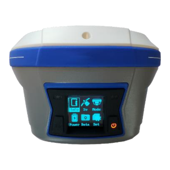
Page 17: Front Panel Operation
This section describes operation using the buttons from the front panel interface. Main Menu After the iG9 starts, the Status Overview Menu will be shown Clicking either button will display the Main Menu: You can move the current selection through each of the items ‘Info, Sv, Mode, Power, Data, Set’ by... -
Page 18: Front Panel: Info
Network Connection Information 4G IMEI number These items are spread over four screens, use the Fn button to move through each of the screens. Click on the Fn button again to return to the main menu. iGage iG9 User Manual... -
Page 19: Front Panel: Sv
Note that if you select any of the Base modes, the receiver always does a ‘Read GPS’ and sets the Base position to the current Autonomous or SBAS/WAAS value. Mode Selection Descriptions: Base External UHF Format sCMRx, RTCM2.3, RTCM3, RTCM3.2, RTD, CMR, CMR+ Cancel iGage iG9 User Manual... - Page 20 Protocol 2AS, CHC, Transparent, TT450S Channel 1 through .. Baud 19200, 9600, 4800 (depends on Protocol) Cancel Rover NTRIP Status Not Logging in (click on OK to select the last used NTRIP or DIP connection) Cancel iGage iG9 User Manual...
-
Page 21: Front Panel: Power
Antenna Height (in Meters): File Format: HCN / RINEX Cancel Advanced selections are not retained until you select OK and then click on Enter. Front Panel: Set From the device Setup screen, you can view and control device settings: iGage iG9 User Manual... - Page 22 WIFI On/Off Click Enter to toggle On and Off WIFI Mode: AP Access Point / STA Station 4G SIM number OEM Board Reset: resets the OEM board, downloads new ephemeris Language: English, Russian, Chinese (Back) iGage iG9 User Manual...
-
Page 23: Compatible Field Software
Carlson SurvPC version 6.07 through 6.08: compatible with IMU Tilt Enabled Note: Carlson has dropped all support for the iG9 receiver from Version 6.09 forward of both SurvCE and SurvPC. Very detailed configuration and use instructions are available for X-PAD, LandStar7 and SurvPC. - Page 24 2-meter pole is 2.25’ offset.) Tilts that result in a higher offset will pause measurements. requests that you hold the receiver nearly still and level. Finally click Accept. Usually, the status goes back and forth between rocking and holding still. iGage iG9 User Manual...
-
Page 25: Carlson Survpc
Note: SurvCE running on Windows Mobile Devices will not work with IMU Tilt. (It appears that the program is too slow to process tilt compensation in real time. To use the IMU, when configuring the iG9 Rover After configuring the iG9 as a Rover, you can under ‘Equip: GPS Rover’... - Page 26 IMU will report that it is uninitialized, the smallest shake (0.01’) of the pole will reinitialize the IMU for another 30- seconds. The ‘Level Tolerance’ is the maximum allowable linear ground distance error allowable. iGage iG9 User Manual...
- Page 27 GSRL: Computed Deviation from Ground Mark – Digital Level Mode, no Corrections Applied Included in Digital Level mode when no corrections are applied. Distance from GNSS Phase Center (PC) to pole point Ground Mark (GM). Header Description iGage iG9 User Manual...
-
Page 28: Landstar7
Tilt tolerance in linear units (feet, meters) LandStar7 CHC LandStar7 directly supports the iGage iG9 receivers, with or without built-in IMU heading + level indicators that allow the position of the rod point to be accurately computed. You can activate the IMU in any of the Survey Store or Stake screens: Click on Settings. - Page 29 And will ask you to alternate between asking you to hold the pole upright: Click the back arrow to return to the survey screen. The IMU status is shown as a green tilt. Clicking on this moveable button allows toggling tilt iGage iG9 User Manual...
-
Page 30: Best Practices For Extending Uhf Radio Range
Best Practices for Extending UHF Radio Range The UHF radio in the iG9 has excellent range. However, range is greatly reduced by other users on the same frequency, damaged antennas, damaged cables and configuration issues. The most common range issues are listed below. If you need to dependably operate at more than 3- miles from your Base, consider purchasing a repeater. -
Page 31: Base Output Power Setting
They require a ground plane at the Base of the antenna and have significantly (about 1/3) the range of the ½ wavelength dipole antennas we supply. The ¼ wavelength antenna are not compatible with the antenna extensions that we supply with a Base. iGage has both factory replacement and heavy- duty super gain antennas available. -
Page 32: Loose Tnc Antenna Connections
Bending ‘out’ the ground contacts on the antenna connector. On the TNC connector, attached to the bottom of the GNSS receiver, bend the small gold fingers ‘in’ to make better contact: Bending the center contacts ‘in’ towards the center. iGage iG9 User Manual... -
Page 33: Configuring The Ig9 Internal Cellular Modem
Configuring the iG9 Internal Cellular Modem Internal GSM Method: To use the internal Cellular Modem in the iG9 receiver, you will need to insert an activated 4G NANO GSM sim card into the card slot in the battery compartment. While the modem is compatible with the Verizon system, it is not Verizon certified and it is probably not possible to activate in the Verizon network. - Page 34 Click ON to turn on the cellular modem. Set Auto Start to Yes, set Auto Connect to Yes. If you are using an iGage Supplied DAC card: set the APN to ‘dac.com.attz’ If you use a ‘True ATT’ SIM card: set the APN to ‘Broadband’ (with capital-‘B’). If you use another type of SIM card enter the appropriate APN for the card.
-
Page 35: Mission Planning
‘Elevation Cutoff’ to a high value like 25 - 30 degrees to simulate heavy canopy. Check GPS, GLONASS and Galileo leaving BeiDou unchecked (as it probably will have minimal contribution.) Click ‘Apply’. Click on ‘Charts’ and roll down to the PDOP chart: iGage iG9 User Manual... - Page 36 GDOPs higher than 3 will present difficult operation, GDOPs higher than 5 may not fix under canopy. Usually waiting 20-minutes for the constellation to improve will make a huge difference. iGage iG9 User Manual...
-
Page 37: Connecting The Ig9 To A Pc Or Smartphone Via Wi-Fi
Connecting the iG9 to a PC or Smartphone via Wi-Fi The iG9 receiver has an internal Wi-Fi Access Point which can be used in conjunction with a PC or smartphone to setup and control every feature of the receiver including firmware updates. - Page 38 Find the iG9 receiver, it will be named ‘GNSS-xxxxxxxx‘ followed by the full serial number of your device: Click on the receiver, then click on ‘Connect’: Enter the Wi-Fi password “12345678” Click on ‘Next’ to connect by Wi-Fi to the GPS head.
- Page 39 From the Wi-Fi interface, you can configure nearly every aspect of the receiver’s operation using the left-hand section tabs and sub-items. iGage iG9 User Manual...
-
Page 40: Programming Ig9 Radio Frequencies And Fcc
Your FCC license will specify one or more frequencies and a ‘Call Sign’ which must be broadcast at least once every 15-minutes. You can download the iGx_RadioChannel.exe tool from the iG9.xyz website, click on Tools, then Radio. The programming tool will run on any PC: With this tool you can create a standard list, modify frequencies, and reorder the frequency list. - Page 41 The ‘Call Sign Status’ should be set to ON, the ‘Call Sign Interval’ should be 15 minutes or less, the ‘Call Sign Message’ should be your FCC Assigned Call Sign. Once entered, click on Save to commit the changes to the internal radio. iGage iG9 User Manual...
-
Page 42: Downloading, Processing And Archiving Static Data
Downloading Data from iG9 GNSS Receiver Summary: Turn on the receiver, wait for it to boot; plug in the USB Cable to your computer. The iG9 receiver mounts as a USB thumb drive (flash drive) on your Windows computer. No special drivers are required. -
Page 43: Starting The Download Tool
You can start the download tool by clicking on the Download shortcut on your desktop: Using the Download Tool Assuming the iG9 GNSS receiver is plugged in and has mounted as a drive letter, just press the 'Download from iGx, X9x, i80' button: The program will automatically switch to the '_New' project and download every new (not previously downloaded) file from your receiver. -
Page 44: Submitting An Occupation To Opus
If the ‘Show Advanced Settings’ is set to “Simple” then the program will skip directly to the ‘Verify Filename to Upload’ screen (shown below.) If ‘Show Advanced Settings’ is set to “Normal”, “Support OPUS-Projects” or “Advanced” then this ‘RINEX Solution’ helper screen is shown: iGage iG9 User Manual... -
Page 45: Setting The Receiver Type
OPUS for processing. Setting the Receiver Type (Hidden when Simple) When files are downloaded from the receiver, the receiver type is associated with the .HCN file. The ‘Receiver Model’ shows an occupation’s associated hardware type: iGage iG9 User Manual... -
Page 46: Viewing The Observation Log
Note: the trimmed length is not reflected in subsequent screens or on the occupation grid. Only the submitted file is trimmed, all the original data remains in the stored occupation. The trim settings must be reloaded after each submission. iGage iG9 User Manual... -
Page 47: Performing Quality Control Checks
At a minimum enter these values: Agency your company name Operator the name of the default operator Email your email address If you change ‘Show Advanced Settings’ from ‘Simple’ to ‘Normal’, ‘Support OPUS Projects’ or ‘Advanced’ additional setup values are shown: iGage iG9 User Manual... -
Page 48: Base Project Folder
There are similar Archive buttons on the main page: one archives the current occupation and the other archives the current project. The download tool does not provide a method to restore these backups, however they are standard ZIP files and the Windows operating system does include a tool to decompress them. iGage iG9 User Manual... -
Page 49: Gps Mounts On Drive
When unchecked (the default,) the download tool will show the observation start and end times in your local time zone. If you check 'Show UTC Time', then the times are displayed in the UTC time zone. iGage iG9 User Manual... -
Page 50: Default Hi
(Hidden when Simple) When you submit a file to OPUS, it is always decimated at the NGS server to 30-second epochs (recording interval = 1 point every 15 seconds.) The default recording interval for most iGage receivers is 1 or 5-seconds. -
Page 51: Your Email
The submit button on the main page tracks this setting and the upload strategy is adjusted to each available service. Additional Information is available on each service on the web: OPUS: https://geodesy.noaa.gov/OPUS/ RTX: http://trimblertx.com AUSPOS: http://www.ga.gov.au/bin/gps.pl IBGE: http://www.ibge.gov.br/home/geociencias/geodesia/ppp/default.shtm Export 8.3 Filename (Hidden when Simple) iGage iG9 User Manual... -
Page 52: Format Extended
Clicking this button runs the CHCData RINEX tool in manual mode. You can browse for HCN files and manually convert them to standard RINEX files. Results are always placed in a subfolder named ‘RINEX’ under the file to be converted. iGage iG9 User Manual... -
Page 53: Mark One File Unread
When ‘Advanced’ is selected, two additional tabs will be displayed: GPS 'Settings' Tab The GPS Settings options on the download tool are not compatible with the iG9. You can use the front panel controls or the Wi-Fi connection to make recording interval changes to the iG9. -
Page 54: Opus: What Is It
Prior to collecting data for OPUS-RS check the latest status map to ensure that OPUS-RS will work. The online OPUS-RS resource http://geodesy.noaa.gov/OPUSI/Plots/Gmap/OPUSRS_sigmap.shtml is updated routinely and reflects the probability that an occupation at a given location will be successful and the expected accuracy for a 15-minute and 1-hour occupation. iGage iG9 User Manual... -
Page 55: Opus-Projects
TIME: 16:08:35 UTC SOFTWARE: page5 1209.04 master93.pl 022814 START: 2014/03/31 00:00:00 EPHEMERIS: igs17861.eph [precise] STOP: 2014/03/31 23:59:00 NAV FILE: brdc0900.14n OBS USED: 45735 / 47174 :97% ANT NAME: TRM29659.00 SCIT # FIXED AMB: 162 / :95% iGage iG9 User Manual... -
Page 56: Survey Feet Vs. International Feet, Scale Factors
OPUS is a great tool for grounding your survey. But OPUS is part of a larger toolset. Before you begin a project take a moment to think about the ‘Big Picture’: What are your GOALS? Required accuracy iGage iG9 User Manual... - Page 57 (>15 degrees) during collection periods. If there are any periods with fewer than 6 SV’s or PDOPS higher than 3, plan on occupying points longer. How long will you observe a site? Again: Are your sites GPS compatible? Are there obstructions higher than 10 degrees? iGage iG9 User Manual...
-
Page 58: Using Opus-Projects
‘OPUS-Project’ checkbox. 3. Now, when you submit an occupation that has been moved to the project, the upload tool will automatically press the ‘OPTIONS’ button on the OPUS submission form and fill in the project identifier: iGage iG9 User Manual... -
Page 59: Best Opus Practices For New And Experienced Users
#3 OPUS-RS is Very dependent on the Number, Availability, Proximity, Distribution and Quality of nearby CORS Stations The initial stage of OPUS-RS processing determines if a network of three to nine CORS stations within 250 KM of the user location can be built. iGage iG9 User Manual... -
Page 60: Daily Vs. Hourly Cors Availability
Daily Hourly Daily means that a full day’s CORS station data is collected and then sometime after midnight UTC the data is archived and becomes available for use as CORS data. Collection is ONCE PER DAY. iGage iG9 User Manual... -
Page 61: Some Areas Of The United States Effectively Only Have Daily Data
The first observation starts at 1:59 pm Mountain Time (20:59 UTC) and ends at 4:59 pm Mountain Time (23:59 UTC.) The second observation starts two minutes after the first at 2:01 pm Mountain Time (21:01 UTC) and ends two minutes after the first observation ends at 5:01 pm Mountain Time. iGage iG9 User Manual... -
Page 62: Offline Cors Stations
PUC2 data available, then you are out of luck. #7 NGS CORS Station Quality When you submit an occupation from your receiver, your receiver’s recorded data is compared with the recorded data from nearby surrounding CORS stations. iGage iG9 User Manual... - Page 63 But how can you determine if a CORS station should be excluded? This is a great question. The best way is to click on the ‘Time Series (short term)’ button. Here is an example of a great station: iGage iG9 User Manual...
- Page 64 You will want to ALWAYS exclude the station from your solutions. If you catch this site on a bad day (and it has a lot of them) you can expect significant elevation and horizontal errors. Even worse sites abound in the NGS array: iGage iG9 User Manual...
-
Page 65: Gps Suitable Locations
10°, or just allow it to track all the way to the horizon (0 degrees Elevation Mask.) Attributes of a great GPS location for collection OPUS ready occupations: No overhead power lines No trees: leaves on or leaves off No power poles (wood or metal) iGage iG9 User Manual... -
Page 66: Worst Case Scenarios
This forces the receiver (and OPUS) to lose lock. This is a location and will greatly increase the RMS error estimates and drop the percentage of observations used. iGage iG9 User Manual... -
Page 67: Large Structures To The South
Even though this location has open water to the South, it is directly underneath large trees. Water can also be a source of significant multipath (see the next section.) This is a location: iGage iG9 User Manual... -
Page 68: Large Reflective Surfaces Nearby
BAD. RBUT (below) is an NGS CORS site and is the closest CORS site to the iGage office in Salt Lake City Utah. This site is hindered by a solid mountain 30° mask to the South. This could be a challenging location for GPS observations and is not a great location for a CORS site. -
Page 69: Power Poles
In North America, the most important sky is to the East, South and West (because there are never any GPS satellites directly north.) So, if you are setting up in a field that is surrounded by large trees, iGage iG9 User Manual... -
Page 70: Longer Observations
At this location, on this day, any one-hour OPUS-RS occupation from 5:30 pm to 9:30 pm will certainly fail. But a one-hour OPUS-RS occupation from 11:30 am to 12:30 pm (or most of the rest of the day) will probably be successful. iGage iG9 User Manual... -
Page 71: Be Procedure Smart: Avoid Blunders
SHMT and radius constants is a common source of error. Confusing slant heights between multiple occupations is a common source of errors. Using ‘inch’ tapes instead of ‘tenths’ tapes is a common source of errors. iGage iG9 User Manual... -
Page 72: Rotate Your Receiver Correctly
NGS Antenna Calibration website. Here is the information from the NGS site for the iG9 receiver: The iG9 should have the MMI (the button/LED panel) turned to face the North. What happens if you don’t rotate the antenna correctly? OPUS has a calibration file for every antenna that relates a change in L1 height offset by the position of the satellite in the sky and the XY offset of the center of the antenna from the center of the mounting nut. -
Page 73: Batteries In Or Batteries Out
If you power an iG9 with external power, you should still include batteries in the head to match the original antenna calibration conditions #12 Why does Modern RTK work where OPUS fails? Yes, OPUS is substantially more finicky than modern GNSS RTK. -
Page 74: Fresnel Zone Considerations
The GPS beam width is spread out in a cigar shaped area known as the ‘Fresnel Zone’. Fresnel is pronounced with a silent-s: ”Frenel”, named after French physicist Monsieur Fresnel. Wikipedia has an excellent article on the Fresnel effect: https://en.wikipedia.org/wiki/Fresnel_zone; be sure to check out the section on ‘Fresnel Zone Clearance’ mid-article. iGage iG9 User Manual... -
Page 75: Opus Best Practices Conclusion
The OPUS family of online tools: OPUS-Static, OPUS-RS, OPUS-Projects are amazing. They allow users to generate reliable X, Y and Height coordinates for GPS suitable locations, anywhere in the world. Hopefully by utilizing the simple rules presented in this chapter, all your jobs will be OPUS-Successful! iGage iG9 User Manual... -
Page 76: Troubleshooting The Ig9 Receiver
Troubleshooting the iG9 Receiver 1. Receiver won’t turn on: Batteries are fully discharged: Charge batteries or use external power. Contacts on battery are dirty: Clean battery and receiver contacts with a soft cloth or soft eraser. Battery is bad: Try another battery. -
Page 77: Ig9 Serial And Usb Io Port Definitions
PPS (Pulse Output) Not Used RS232-RX (Input) Figure 3 iG9 7-Pin Serial IO Lemo Connection Information USB Port Definition The iG9 has a standard USB Type-C connector. When connected to a computer with a USB cable, the receiver mounts as a lettered disk drive. -
Page 78: Upgrading Firmware
UHF Radio Board All three are updated using a similar process via the Wi-Fi interface. Updating Main Board Firmware Download the Main Board firmware from the iG9 website: https://iG9.xyz/out/firmware/index.htm Follow the instructions in section “Connecting the iG9 to a PC or Smartphone via Wi-Fi”... - Page 79 Click on Firmware, then ‘Upgrade’, then ‘Browse’ and find the firmware finally click on ‘Confirm’. The receiver will reboot twice during the upgrade process. iGage iG9 User Manual...
-
Page 80: Gnss Oem Reset
GNSS OEM Reset It is possible to reset the iG9 from the Front Panel and from the web interface. This procedure should not be required for normal operation. Web Interface Reset Connect a PC, tablet or smartphone to the WiFi web interface of the iG9 as shown in ‘Connecting... - Page 81 Click the Fn key once to OK: The receiver will display ‘Reset OEM Board, Resetting…’ then after 15-seconds the receiver will reboot. Resetting the engine erases the OEM Engine memory, erases all satellite data and reboots the OEM engine. iGage iG9 User Manual...
-
Page 82: Ig9 Antenna Model
Antenna Model NONE” The iG9 and iG9a receivers have an NGS calibration “CHCI90 The .atx and .gra files for the iG9 can be found on the website https://iG9.xyz ; click on Tools, then Antenna Summary 114.0 mm 91.07 mm Radius 55.3 mm... -
Page 83: Slant Height' To 'Vertical Height
Slant Height Measurement Point (SHMP) offset from receiver bottom Examples Measured Slant s Slant s Vertical (feet) v (m) 6.965 2.123 2.0474 5.148 1.569 1.4931 iGage iG9 User Manual... -
Page 84: Warranty
IMC is “iGage Mapping Corporation” of Salt Lake City Utah USA. IMC warrants the iG9 receivers, which we sell, to be free of defects in material and workmanship and will conform to our published specifications for these periods:... -
Page 85: Rma
This written warranty is the complete, final, and exclusive agreement between IMC and the Purchaser. To obtain warranty service from iGage Mapping Corporation the purchaser must obtain a return materials authorization (RMA) number prior to shipping by calling +1-801-412-0011 Or by email: info@igage.com...