Table of Contents
Advertisement
Quick Links
IM-4055
January 2022
Electronic commutation (EC) is the latest motor technology to be
used in direct drive fans. Also known in the industry as Brush Free
or Brushless DC, the EC motors utilize an electronic circuit board to
control the functionality of the motor. The motor operates off of
115V or 208/230V AC single phase power or 208/230V or 460 three
phase power, which is converted to DC power within the motor's
circuitry. The result is a highly efficient motor with an expanded
speed control range and a variety of speed control options from
which to choose.
REVIEW AMCA BULLETIN 410 PRIOR TO INSTALLATION
This manual has been prepared to guide the users of electronically commutated motors in the proper installation, operation
and maintenance procedures to ensure maximum equipment life with trouble-free operation. For safe installation, startup
and operational life of this equipment, it is important that all involved with the equipment be well versed in proper fan safety
practices and read this manual. It is the user's responsibility to make sure that all requirements of good safety practices and any
applicable safety codes are strictly adhered to. Because of the wide variety of equipment covered in this manual, the instructions
given here are general in nature. Additional product and engineering information is available at www.tcf.com.
Refer to the safety section(s) in this manual prior to installing or servicing the fan. The most current version of this installation and
maintenance manual can be found on our website at www.tcf.com/resources/im-manuals.
Table of Contents
Safety & Hazard Warnings ...........................................................................................................................................................................2
Shipping & Receiving ....................................................................................................................................................................................2
Handling ....................................................................................................................................................................................................... 3
Unit Storage ................................................................................................................................................................................................. 4
General Installation ...................................................................................................................................................................................... 4
Electrical Connection ................................................................................................................................................................................... 5
Speed Control Options: ODP & TENV Motors .......................................................................................................................................5-10
Speed Control Options: TEFC Motors ................................................................................................................................................... 11-12
Speed Control Options: OP Motors ........................................................................................................................................................... 1 3
Maintenance ...............................................................................................................................................................................................1 4
Troubleshooting ..........................................................................................................................................................................................1 4
Fan Maintenance Log ................................................................................................................................................................................. 1 5
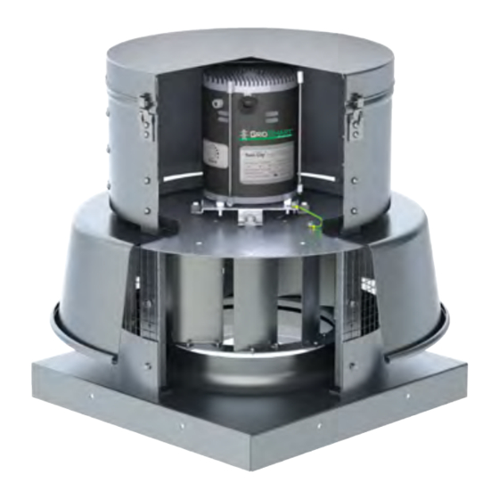
Electronically
Commutated Motors
Installation, Operation & Maintenance Manual
Model DCRD
with EC motor
SAFETY NOTICE
Twin City Fan
Advertisement
Table of Contents

Summary of Contents for TCF DCRD
-
Page 1: Table Of Contents
It is the user’s responsibility to make sure that all requirements of good safety practices and any applicable safety codes are strictly adhered to. Because of the wide variety of equipment covered in this manual, the instructions given here are general in nature. Additional product and engineering information is available at www.tcf.com. SAFETY NOTICE Refer to the safety section(s) in this manual prior to installing or servicing the fan. -
Page 2: Safety & Hazard Warnings
IM-4055 Safety & Hazard Warnings For general safety practices for air moving equipment, see AMCA Bulletin 410. Twin City Fan & Blower offers many safety accessories. These safety devices include (but are not limited to) belt guards, shaft guards, inlet and discharge screens. The use and suitability of safety devices is the responsibility of the purchaser. -
Page 3: Handling
IM-4055 Handling Handling of all air moving equipment should be conducted by trained personnel and be consistent with safe handling practices. Verify the lift capacity and operating condition of handling equipment. When using hoisting equipment, only qualified and trained personnel should operate the equipment. Units shipped completely assembled may be lifted with slings and spreader bars. -
Page 4: Unit Storage
IM-4055 Unit Storage If fan installation is to be delayed, store the unit in an environmentally stable and protected area. During storage, the fan should not be subjected to vibration from external sources or bearing damage may occur. The unit should be reasonably protected from any accidental impacts. -
Page 5: Electrical Connection
200-1800 GridPoint/0-10V/RMD 67001701 2,3,4 with a remote speed control, either field 300-1800 MMD/0-10V/RMD 67001003 1,2,4 supplied or supplied by TCF. See table to 1/2 208-230 350-1800 MMD/0-10V/RMD 67001103 1,2,4 the right for available control methods and 1/2 115/230 200-1800 GridPoint/0-10V/RMD... - Page 6 0-1.9V DC signal is present. See table below for speed reference charts. It is the responsibility of the installer/controls engineer to ensure that any field supplied controls are compatible and functional with this motor technology. TCF is not responsible for field supplied or customer designed fan or motor controls.
- Page 7 0-10V DC option. This option includes a 115V or 230V (depending upon the motor voltage selected) to 24V AC transformer mounted in the NEMA electrical enclosure. On models DCRD, DCRU/R, DCRW/R, DCLH/P and DCV the junction box for the transformer will be located within the fan motor enclosure/weather cover. On models DSI and TCPE, the junction box for the transformer will be located on the exterior of the fan.
- Page 8 1800 1800 180BE 1200 1200 150ANE 1800 1800 165L 1800 1604 165ANE 1200 1200 182L 1200 1508 DCRD DCLH & DCLP Motor Motor Max Fan Motor Motor Max Fan Motor Motor Max Fan Size Size Size 060BE 1800 1800 1800...
- Page 9 GROUND 110-120 VAC WHITE DISCONNECT 24 VAC YELLOW BLUE BLACK REMOTE DIAL (TCF) SIGNAL FIELD INSTALLED FACTORY PROVIDED 0 - 10 V 24 VAC Note: Diagram refers to motors 67001001, 67001003, 67001004, 67001005, 67001008, 67001105. Figure 2. Remote Mounted Dial Wiring Diagram — 208-230VAC Single Phase...
- Page 10 115 OR 230 VAC GROUND WHITE DISCONNECT 24 VAC YELLOW BLUE BLACK REMOTE DIAL (TCF) SIGNAL FIELD INSTALLED FACTORY PROVIDED 0 - 10 V 24 VAC Note: Diagram refers to motors 67001701, 67001703, 67001704, 67001705, 67001715. Installation, Operation & Maintenance Manual...
-
Page 11: Speed Control Options: Tefc Motors
IM-4055 Speed Control Options: TEFC Motors This section covers the motors listed in the chart on the right. Motor Voltage/Phase Part Numbers Installation 67002205 115/208-230/1 1. Connect the motor to AC power and ground the external speed control. 67002107 208-230/1 Follow Figures 4 and 5 below for appropriate voltage. - Page 12 (DGND) It is the responsibility of the installer/controls engineer to ensure that any field supplied controls are compatible and functional with this motor technology. TCF is not responsible for field supplied or customer designed fan or motor controls. 3. Verify rotation of motor is correct by energizing the motor and checking that the rotation matches the fan rotation label.
-
Page 13: Speed Control Options: Op Motors
IM-4055 Speed Control Options: OP Motors Connections This motor is designed to be connected to the three-phase supply mains at all times. Motor operation is controlled by an analog DC voltage signal. The motor is shipped with all necessary internal connections made for signal, power and ground connections. The three-phase AC lines are labeled “L1”, “L2”... -
Page 14: Maintenance
IM-4055 Maintenance These motors use brushless technology with sealed bearings so no maintenance is required other than keeping the motors dry and free of dirt, dust and debris. Always keep records of the maintenance that is performed. Troubleshooting Remote Dial does not vary the motor speed (all motor types, except OP) •... -
Page 15: Fan Maintenance Log
IM-4055 Fan Maintenance Log Model Number__________________________ Serial Number __________________________ Date Completed Maintenance Performed By Comments Installation, Operation & Maintenance Manual... - Page 16 Twin City Fan TWIN CITY FAN & BLOWER | WWW.TCF.COM 5959 Trenton Lane N | Minneapolis, MN 55442 | Phone: 763-551-7600 | Fax: 763-551-7601 ©2012-2022 Twin City Fan Companies, Ltd.