
Related Manuals for D-Link D DFL-500 DFL-500


Summary of Contents for D-Link D DFL-500 DFL-500
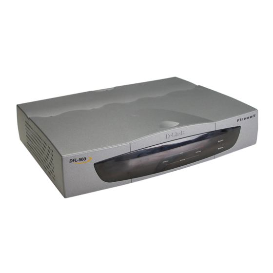
- Page 1 D-Link DFL-500 Network Security Firewall Manual Building Networks for People DFL-500 User Manual...
- Page 2 © Copyright 2003 D-Link Systems, Inc. All rights reserved. No part of this publication including text, examples, diagrams or illustrations may be reproduced, transmitted, or translated in any form or by any means, electronic, mechanical, manual, optical or otherwise, for any purpose, without prior written permission of D-Link Systems, Inc.
-
Page 3: Table Of Contents
Table of Contents Introduction ... 8 NAT/Route mode and Transparent mode... 8 NAT/Route mode ... 8 Transparent mode ... 8 About this document ... 8 For more information... 9 Customer service and technical support... 9 Getting started... 10 Package contents ... 10 Mounting ... - Page 4 Firewall configuration ... 23 NAT/Route mode and Transparent mode... 24 NAT/Route mode ... 24 Transparent mode ... 24 Changing to Transparent mode ... 24 Changing to NAT/Route mode... 24 Adding NAT/Route mode policies ... 24 Adding Transparent mode policies ... 27 Configuring policy lists ...
- Page 5 Configuring user groups... 46 Adding user groups... 46 Deleting user groups... 47 IPSec VPNs ... 48 Interoperability with IPSec VPN products ... 48 Configuring AutoIKE key IPSec VPN... 49 Configuring manual key IPSec VPN ... 50 Configuring dialup VPN... 50 Configuring a VPN concentrator for hub and spoke VPN...
- Page 6 Changing the URL block message ... 74 Downloading the URL block list ... 74 Uploading a URL block list... 74 Removing scripts from web pages... 75 Exempting URLs from content or URL blocking ... 75 Adding URLs to the Exempt URL List ... 76 Clearing the Exempt URL list...
- Page 7 System configuration ... 96 Setting system date and time ... 97 Changing web-based manager options... 98 Adding and editing administrator accounts... 98 Configuring SNMP ... 99 Glossary ... 101 Index ... 104 Technical Support ... 116 Limited Warranty ... 119 Registration ...
-
Page 8: Introduction
Introduction The DFL-500 Network Protection Gateway (NPG) is an easy-to-deploy and easy-to-administer solution that delivers exceptional value and performance for small office and home office (SOHO) applications. Your DFL-500 is a dedicated easily managed security device that delivers a full suite of capabilities that include firewall, VPN, traffic shaping, and web content filtering. -
Page 9: For More Information
DFL-500 CLI Reference Guide • DFL-500 online help Customer service and technical support For updated product documentation, technical support information, and other resources, please visit D-Link local web site. You can contact D-Link Technical Support at your local D-Link office: •... -
Page 10: Getting Started
Getting started This chapter describes unpacking, setting up, and powering on your DFL-500 NPG. When you have completed the procedures in this chapter, you can proceed to one of the following: • If you are going to run your DFL-500 NPG in NAT/Route mode, go to •... -
Page 11: Powering On
Dimensions • 8.63 x 6.13 x 1.38 in. (21.9 x 15.6 x 3.5 cm) Weight • 1.5 lb. (0.68 kg) Power requirements • DC input voltage: 5 V • DC input current: 3 A Environmental specifications • Operating temperature: 32 to 104°F (0 to 40°C) •... -
Page 12: Initial Configuration
Front and back view of the DFL-500 NPG Initial configuration When the DFL-500 NPG is first powered on, it is running in NAT/Route mode and has the basic configuration listed in DFL-500 NPG initial power on DFL-500 NPG initial power on settings Operating mode: Administrator account: Internal interface:... -
Page 13: Connecting To The Command Line Interface (Cli)
Type admin in the Name field and select Login. The Register Now window appears. Use the information on this window to register your DFL-500 NPG. Register your DFL-500 NPG so that D-Link can contact you for firmware updates. DFL-500 login Connecting to the command line interface (CLI) As an alternative to the web-based manager, you can install and configure the DFL-500 NPG using the CLI. -
Page 14: Next Steps
Data bits Parity None Stop bits Flow control None • Press Enter to connect to the DFL-500 CLI. The following prompt appears: DFL-500 login: • Type admin and press Enter. The following prompt appears: Type ? for a list of commands. For information on how to use the CLI, see the DFL-500 CLI Reference Guide . -
Page 15: Nat/Route Mode Installation
NAT/Route mode installation This chapter describes how to install your DFL-500 NPG in NAT/Route mode. If you want to install the DFL- 500 NPG in Transparent mode, see This chapter includes: • Preparing to configure NAT/Route mode • Using the setup wizard •... -
Page 16: Using The Setup Wizard
The DFL-500 NPG contains a DHCP server that you can configure to automatically set the addresses of the computers on your internal network. Using the setup wizard From the web-based manager, you can use the setup wizard to create the initial configuration of your DFL- 500 NPG. -
Page 17: Connecting To Your Networks
• Set the IP address and netmask of the external interface to the external IP address and netmask that you recorded in NAT/Route mode To set the manual IP address and netmask, enter: set system interface external static ip <IP address> <netmask> Example set system interface external static ip 204.23.1.5 255.255.255.0 To set the external interface to use DHCP, enter:... -
Page 18: Configuring Your Internal Network
DFL-500 NPG network connections Configuring your internal network If you are running the DFL-500 NPG in NAT/Route mode, your internal network must be configured to route all internet traffic to the address of the internal interface of the DFL-500 NPG. This means changing the default gateway address of all computers connected directly to the internal network. -
Page 19: Transparent Mode Installation
Transparent mode installation This chapter describes how to install your DFL-500 NPG in Transparent mode. If you want to install the DFL- 500 NPG in NAT/Route mode, see This chapter includes: • Preparing to configure Transparent mode • Using the setup wizard •... -
Page 20: Starting The Setup Wizard
Starting the setup wizard • Select Easy Setup Wizard (the button in the upper right corner of the web-based manager). • Use the information that you gathered in the Next button to step through the wizard pages. • Confirm your configuration settings and then select Finish and Close. Reconnecting to the web-based manager If you changed the IP address of the management interface while you were using the setup wizard, you must reconnect to the web-based manager using a new IP address. -
Page 21: Configure The Transparent Mode Default Gateway
The CLI lists the Management IP address and netmask. Configure the Transparent mode default gateway • Login to the CLI if you are not already logged in. • Set the default route to the Default Gateway that you recorded in set system route number <number>... - Page 22 DFL-500 network connections DFL-500 User Manual...
-
Page 23: Firewall Configuration
Firewall configuration By default, the users on your internal network can connect through the DFL-500 NPG to the Internet. The firewall blocks all other connections. The firewall is configured with a default policy that matches any connection request received from the internal network and instructs the firewall to forward the connection to the Internet. -
Page 24: Nat/Route Mode And Transparent Mode
NAT/Route mode and Transparent mode The first step in configuring firewall policies is to configure the mode for the firewall. The firewall can run in NAT/Route mode or Transparent mode. NAT/Route mode Run the DFL-500 NPG in NAT/Route mode to protect a private network from a public network. When the DFL-500 NPG is running in NAT/Route mode, you can connect a private network to the internal interface and a public network, such as the Internet, to the external interface. - Page 25 You can also select Insert Policy before specific policy. • Configure the policy: Select an address or address group that matches the source address of the packet. Before you Source can add this address to a policy, you must add it to the source interface. To add an address, see Addresses.
- Page 26 Telnet, or FTP. For users to be able to authenticate you must add an HTTP, Telnet, or FTP policy that is configured for authentication. When users attempt to connect through the firewall using this policy they are prompted to enter a firewall username and password. If you want users to authenticate to use other services (for example POP3 or IMAP) you can create a service group that includes the services for which you want to require authentication as well as HTTP, Telnet, and FTP.
-
Page 27: Adding Transparent Mode Policies
Adding a NAT/Route Int -> Ext policy Adding Transparent mode policies Add Transparent mode policies to control the network traffic that is allowed to pass through the firewall when you are running the it in Transparent mode. • Go to Firewall > Policy . •... - Page 28 Select how the firewall should respond when the policy matches a connection attempt. You can Action configure the policy to direct the firewall to ACCEPT the connection or DENY the connection. If you select ACCEPT, you can also configure Authentication for the policy. Select Log Traffic to write messages to the traffic log whenever the policy processes a Log Traffic connection.
-
Page 29: Configuring Policy Lists
Adding a Transparent mode Int -> Ext policy Configuring policy lists The firewall matches policies by searching for a match starting at the top of the policy list and moving down until it finds the first match. You must arrange policies in the policy list from more specific to more general. For example, the default policy is a very general policy because it matches all connection attempts. -
Page 30: Changing The Order Of Policies In A Policy List
Policies that require authentication must be added to the policy list above matching policies that do not; otherwise, the policy that does not require authentication is selected first. Changing the order of policies in a policy list • Go to Firewall > Policy . •... -
Page 31: Adding Addresses
Adding addresses • Go to Firewall > Address . • Select the interface to which to add the address. The list of addresses added to that interface is displayed. • Select New to add a new address to the selected interface. •... -
Page 32: Organizing Addresses Into Address Groups
Organizing addresses into address groups You can organize related addresses into address groups to make it easier to add policies. For example, if you add three addresses, and then add them to an address group, you only have to add one policy for the address group rather than three separate policies, one for each address. -
Page 33: Predefined Services
• Predefined services • Providing access to custom services • Grouping services Predefined services To view the list of predefined services, go to Firewall > Service > Pre-defined . You can add predefined services to any policy. Providing access to custom services Add a custom service if you need to create a policy for a service that is not in the predefined service list. -
Page 34: Schedules
Adding a service group • To add services to the service group, select a service from the Available Services list and select the right arrow to copy it to the Members list. • To remove services from the service group, select a service from the Members list and select the left arrow to remove it from the group. -
Page 35: Creating Recurring Schedules
• Set the Start date and time for the schedule. Set Start and Stop times to 00 for the schedule to cover the entire day. • Set the Stop date and time for the schedule. One-time schedules use the 24-hour clock. •... -
Page 36: Adding Static Nat Virtual Ips
create an external address for the web server on the Internet. You must then add a virtual IP to the firewall that maps the external IP address of the web server to the actual address of the web server on your internal network. -
Page 37: Using Port Forwarding Virtual Ips
Adding a static NAT virtual IP • In the Map to IP field, enter the real IP address on the more secure network, for example, the IP address of a web server on your internal network. The firewall translates the source address of outbound packets from the host with the Map to IP address to the virtual IP External IP Address, instead of the firewall external address. -
Page 38: Adding Policies With Virtual Ips
Adding a Port Forwarding virtual IP • Enter the External Service Port number for which to configure port forwarding. The external service port number must match the destination port of the packets to be forwarded. For example, if the virtual IP provides access from the Internet to a Web server on your internal network, the external service port number would be 80 (the HTTP port). -
Page 39: Ip Pools
Destination Select the virtual IP. Schedule Select a schedule as required. Select the service that matches the Map to Service that you selected for the port-forwarding Service virtual IP. Set action to ACCEPT to accept connections to the internal server. You can also select DENY to Action deny access. -
Page 40: Ip/Mac Binding
Adding an IP Pool IP/MAC binding IP/MAC binding protects the DFL-500 NPG and your network from IP spoofing attacks. IP spoofing attempts to use the IP address of a trusted computer to connect to or through the firewall from a different computer. The IP address of a computer can easily be changed to a trusted address, but MAC addresses are added to ethernet cards at the factory and cannot easily be changed. -
Page 41: Configuring Ip/Mac Binding For Packets Going To The Firewall
All packets that would normally be matched with policies to be able to go through the firewall are first compared with the entries in the IP/MAC binding list. If a match is found, then the firewall attempts to match the packet with a policy. For example, if the IP/MAC pair IP 1.1.1.1 and 12:34:56:78:90:ab:cd is added to the IP/MAC binding list: •... -
Page 42: Viewing The Dynamic Ip/Mac List
Viewing the dynamic IP/MAC list • Go to Firewall > IP/MAC Binding > Dynamic IP/MAC . Enabling IP/MAC binding • Go to Firewall > IP/MAC Binding > Setting . • Select Enable IP/MAC binding going through the firewall to turn on IP/MAC binding for packets that could be matched by policies. -
Page 43: Users And Authentication
Users and authentication DFL-500 NPGs support user authentication to the DFL-500 user database or to a RADIUS server. You can add user names to the DFL-500 user database and then add a password to allow the user to authenticate using the internal database. You can also add the name of a RADIUS server and select RADIUS to allow the user to authenticate using the selected RADIUS server. -
Page 44: Deleting User Names From The Internal Database
• Select New to add a new user name. Adding a user name • Enter the user name. The user name can contain numbers (0-9) and uppercase and lowercase letters (A-Z, a-z), and the special characters - and _. Other special characters and spaces are not allowed. •... -
Page 45: Configuring Radius Support
Deleting the user name deletes the authentication configured for the user. Configuring RADIUS support If you have configured RADIUS support and a user is required to authenticate using a RADIUS server, the DFL-500 NPG contacts the RADIUS server for authentication. When using a RADIUS server for user authentication, PPTP and L2TP encryption is not supported and you should not select Require data encryption when configuring Windows clients for PPTP or L2TP. -
Page 46: Configuring User Groups
Configuring user groups Use the following information to add user groups to your DFL-500 configuration. You can add user names and RADIUS servers to user groups. You can then add user groups to: • Policies that require authentication policies). Only users in the selected user group or that can authenticate with the RADIUS servers added to the user group can authenticate with these policies. -
Page 47: Deleting User Groups
Adding a user group • To remove users or RADIUS servers from the user group, select a user or RADIUS server from the Members list and select the left arrow to remove the name or RADIUS server from the group. •... -
Page 48: Ipsec Vpns
IPSec VPNs Using IPSec Virtual Private Networking (VPN), you can securely join two or more widely separated private networks or computers together through the Internet. For example, if you are away from home, you can use a VPN to securely connect through your DFL-500 NPG to your home network. If you tele-commute, you can securely connect from your home network through your DFL-500 NPG to your employer's private network. -
Page 49: Configuring Autoike Key Ipsec Vpn
VPN concentrator for hub and spoke configurations To successfully establish an IPSec VPN tunnel, the DFL-500 IPSec VPN configuration must be compatible with the third-party product IPSec VPN configuration. D-Link has tested DFL-500 VPN interoperability with the following third-party products: •... -
Page 50: Configuring Manual Key Ipsec Vpn
Adding an encrypt Configuring manual key IPSec VPN A manual key VPN configuration consists of a manual key VPN tunnel, the source and destination addresses for both ends of the tunnel, and an encrypt policy to control access to the VPN tunnel. To create a manual key VPN configuration: •... -
Page 51: Configuring The Vpn Concentrator
Configuring the VPN concentrator On the VPN concentrator network, you must create one VPN tunnel for each of the prospective VPN concentrator members and then add these tunnels to a VPN concentrator. You can add both AutoIKE and manual key VPN tunnels to a VPN concentrator. Encrypt policies control the direction of traffic through the VPN concentrator. -
Page 52: Configuring Ipsec Redundancy
Adding an AutoIKE key VPN Or, add a manual key VPN tunnel. Adding a manual key VPN • Add one encrypt policy between the member VPN and the VPN concentrator. Use the following configuration: Source Member VPN address. Destination VPN concentrator address. Action ENCRYPT VPN Tunnel... -
Page 53: Adding A Remote Gateway
The source and destination of both policies must be the same. Add a different AutoIKE key tunnel to each policy. Adding an encrypt Adding a remote gateway Add a remote gateway configuration to define the parameters that the DFL-500 NPG uses to connect to and establish an AutoIKE key VPN tunnel with a remote VPN gateway or a remote VPN client. -
Page 54: About Dialup Vpn Authentication
Mode. Enter the IP address of the dialup user or the domain name of the dialup user (for example, domain.com). If you do not add a local ID, the DFL-500 external interface automatically becomes the Local ID. For information about the Local ID, see authentication. - Page 55 For each variation, the remote gateway field of the dialup server remote gateway configuration must be set to dialup user and all of the clients must have their remote gateway or equivalent set to the static IP address of the remote gateway server. The following sections describe how to configure authentication on the server and clients for each of these variations.
-
Page 56: About Dh Groups
Aggressive mode with no user group Field Server User Group None Mode Aggressive Authentication Key The server and the clients must have the same authentication key. Local ID empty Aggressive mode with a user group selected In this configuration, the server and the clients use aggressive mode for key exchange. A user group is selected in the server dialup remote gateway. -
Page 57: About Nat Traversal
About NAT traversal NAT (Network Address Translation) converts private IP addresses into routable public IP addresses. The DFL-500 NPG uses NAPT (Network Address Port Translation), in which both IP addresses and ports are mapped. Mapping both components allows multiple private IP addresses to use a single public IP address. Because a NAT device modifies the original IP address of an IPSec packet, the packet fails an integrity check. -
Page 58: About The P2 Proposal
Autokey Keep Enable Autokey Keep Alive to keep the VPN tunnel running even if no data is being Alive processed. Select a concentrator if you want the tunnel to be part of a hub and spoke VPN configuration. If you use the procedure, Concentrator concentrator, the next time you open the tunnel, the Concentrator field displays the name of the concentrator to which you have added the tunnel. -
Page 59: About Perfect Forward Secrecy (Pfs)
The DFL-500 NPG sends an alert email when replay detection detects a replay packet. To receive the alert email, you must configure alert email and select "Enable alert email for critical firewall/VPN events or violations". For information about alert email, see About perfect forward secrecy (PFS) Perfect forward secrecy (PFS) improves the security of a VPN tunnel by making sure that each key created during phase 2 is not related to the keys created during phase 1 or to other keys created during phase 2. -
Page 60: Adding A Vpn Concentrator
For all 3DES encryption algorithms, enter three hexadecimal numbers of up to 16 digits each. Use the same encryption key at both ends of the tunnel. Required for encryption algorithms that include MD5 or SHA1 authentication. For MD5 authentication, enter two hexadecimal numbers of 16 digits each. Use the same Authentication authentication key at both ends of the tunnel. -
Page 61: Adding An Encrypt Policy
• Select OK to add the VPN concentrator. Adding a VPN concentrator Adding an encrypt policy Add encrypt policies to connect users on your internal network to a VPN tunnel. Encrypt policies are always Int -> Ext policies. The source of the encrypt policy must be an address on your internal network. The destination of this policy must be the address of the network behind the remote DFL-500 NPG gateway. - Page 62 The destination address is the IP address of the remote network behind the remote VPN gateway. The destination address is the IP address of the remote network behind the remote VPN gateway. If you are adding an encrypt policy for a VPN with a remote VPN client connected to the Internet, the destination address should be the Internet address of the client computer.
-
Page 63: Viewing Vpn Tunnel Status
Allow Select Allow outbound to enable outbound users to connect to the destination address. outbound Inbound The DFL-500 NPG translates the source address of incoming packets to the IP address of the DFL-500 interface connected to the source address network. Outbound The DFL-500 NPG translates the source address of outgoing packets to the IP address of the DFL-500 interface connected to the destination address network. -
Page 64: Viewing Dialup Vpn Connection Status
AutoIKE key tunnel status Viewing dialup VPN connection status You can use the dialup monitor to view the status of dialup VPNs. The dialup monitor lists the remote gateways and the active VPN tunnels for each gateway. The monitor also lists the tunnel lifetime, timeout, proxy ID source, and proxy ID destination for each tunnel. - Page 65 To confirm that a VPN between a network and one or more clients has been configured correctly, start a VPN client and use the ping command to connect to a computer on the internal network. The VPN tunnel initializes automatically when the client makes a connection attempt. You can start the tunnel and test it at the same time by pinging from the client to an address on the internal network.
-
Page 66: Pptp And L2Tp Vpns
PPTP and L2TP VPNs Using PPTP and L2TP Virtual Private Networking (VPN), you can create a secure connection between a client computer running Microsoft Windows and your internal network. PPTP is a Windows VPN standard. You can use PPTP to connect computers running Windows to a DFL-500 NPG-protected private network without using third-party VPN client software. -
Page 67: Configuring The Dfl-500 Npg As A Pptp Gateway
PPTP VPN between a Windows client and the DFL-500 NPG Configuring the DFL-500 NPG as a PPTP gateway • Create a user group for your PPTP users. Users and authentication. • Go to VPN > PPTP > PPTP Range . •... - Page 68 Example PPTP Range configuration When using a RADIUS server for user authentication, PPTP and L2TP encryption is not supported and you should not select Require data encryption when configuring Windows clients for PPTP or L2TP. • Add the addresses from the PPTP address range to the external interface address list. The addresses can be grouped into an external address group.
-
Page 69: L2Tp Vpn Configuration
L2TP VPN configuration L2TP clients must be able to authenticate with the DFL-500 NPG to start a L2TP session. To support L2TP authentication, you must add a user group to the DFL-500 NPG configuration. This user group can contain users added to the DFL-500 NPG user database, RADIUS servers, or both. After you have added a user group, configure your DFL-500 NPG to support L2TP by enabling L2TP and specifying a L2TP address range. - Page 70 • Select Enable L2TP. • Enter the Starting IP and the Ending IP for the L2TP address range. • Select the User Group that you added in step • Select Apply to enable L2TP through the DFL-500 NPG. Sample L2TP address range configuration When using a RADIUS server for user authentication, PPTP and L2TP encryption is not supported and you should not select Require data encryption when configuring Windows clients for PPTP or L2TP.
-
Page 71: Web Content Filtering
Web content filtering Use DFL-500 web content filtering for: • Enabling web content Filtering • Blocking web pages that contain unwanted content • Blocking access to URLs • Removing scripts from web pages • Exempting URLs from content or URL blocking Enabling web content Filtering Enable web content filtering by selecting the Web filter option in firewall policies that allow HTTP connections through the DFL-500 NPG. -
Page 72: Clearing The Banned Word List
The DFL-500 NPG is now configured to block web pages containing words and phrases added to the banned word list. • Select New to add a word or phrase to the banned word list. • Choose a language or character set for the banned word or phrase. You can choose Western, Chinese Simplified, Chinese Traditional, Japanese, or Korean. -
Page 73: Blocking Access To Urls
• Select Backup Banned Word List The DFL-500 NPG downloads the banned word list to a text file on the management computer. You can specify a location to which to download the text file as well as a name for the text file. You can make changes to the text file and upload it from your management computer to the DFL-500 NPG. -
Page 74: Clearing The Url Block List
URL blocking does not block access to other services that users can access with a web browser. For example, URL blocking does not block access to ftp://ftp.badsite.com . Instead, you can use firewall policies to deny FTP connections. • Select Enable to block the URL. •... -
Page 75: Removing Scripts From Web Pages
You can add a URL list created by a third-party URL block or blacklist service. For example, you can download the squidGuard blacklists, available at http://www.squidguard.org/blacklist/ as a starting point for creating your own URL block list. Three times a week, the squidGuard robot searches the web for new URLs to add to the blacklists. -
Page 76: Adding Urls To The Exempt Url List
• Clearing the Exempt URL list • Downloading the Exempt URL list • Uploading an Exempt URL list Adding URLs to the Exempt URL List • Go to Web Filter > Exempt URL . • Select New to add an entry to the Exempt URL list. •... -
Page 77: Uploading An Exempt Url List
Uploading an Exempt URL list You can create an Exempt URL list in a text editor and then upload the text file to the DFL-500 NPG. Add one URL to each line of the text file. You can follow the URL with a space and then a 1 to enable or a zero (0) to disable the URL. -
Page 78: Logging And Reporting
Logging and reporting You can configure the DFL-500 NPG to record 3 types of logs: • Traffic logs record all traffic that attempts to connect through the DFL-500 NPG. • Event logs record management and activity events. You can also use Log & Report to configure the DFL-500 NPG to send alert emails for: •... -
Page 79: Selecting What To Log
Example log settings Selecting what to log Use the following procedure to configure the type of information recorded in DFL-500 logs. • Go to Log&Report > Log setting . • Select Log All Internal Traffic To Firewall to record all connections to the internal interface. This setting is not available in Transparent mode. -
Page 80: Configuring Alert Email
Configuring alert email • Go to System > Network > DNS . • If they have not already been added, add the primary and secondary DNS server addresses provided to you by your ISP. Because the DFL-500 NPG uses the SMTP server name to connect to the mail server, it must be able to look up this name on your DNS server. -
Page 81: Administration
Administration This chapter describes how to use the web-based manager to administer and maintain the DFL-500 NPG. It contains the following sections: • System status • Upgrading the DFL-500 NPG firmware • Displaying the DFL-500 NPG serial number • Backing up system settings •... -
Page 82: Upgrading The Dfl-500 Npg Firmware
System status monitor Upgrading the DFL-500 NPG firmware D-Link releases new versions of the DFL-500 NPG firmware periodically. You can download the upgrade from D-Link and use one of the following procedures to upgrade the firmware on your DFL-500 NPG: •... - Page 83 • Enter the following command to restart the DFL-500 NPG: > execute reboot As the DFL-500 NPG reboots, messages similar to the following appear: BIOS Version 2.2 Serial number: FGT-502801021075 SDRAM Initialization. Scanning PCI Bus...Done. Total RAM: 256M Enabling Cache...Done. Allocating PCI Resources...Done.
-
Page 84: Displaying The Dfl-500 Npg Serial Number
When the interface addresses are changed, you can access the DFL-500 from the web-based manager and restore your configuration files and content and URL filtering lists. Displaying the DFL-500 NPG serial number • Go to System > Status . The serial number is displayed in the Status window. The serial number is specific to your DFL-500 NPG and does not change with firmware upgrades. -
Page 85: Changing To Transparent Mode
This procedure deletes the changes that you have made to the DFL-500 NPG configuration and reverts the system to its original configuration, including resetting interface addresses. • Go to System > Status . • Select Restore Factory Defaults. • Select OK to confirm. The DFL-500 NPG restarts with the configuration that it had when it was first powered on. -
Page 86: Restarting The Dfl-500 Npg
The DFL-500 NPG changes operation mode. • To reconnect to the web-based manager, browse to the interface that you have configured for management access using https:// followed by the IP address of the interface. Restarting the DFL-500 NPG Use the following procedure to restart the DFL-500 NPG: •... -
Page 87: Network Configuration
System status monitor At the top of the display, the system status monitor shows: CPU usage Memory usage Up time Total Number of Sessions The total number of active communication sessions to and through the DFL-500 NPG. Each line of the system status monitor displays the following information about each active firewall connection: Protocol The service type or protocol of the connection. -
Page 88: Configuring The Internal Interface
Configuring the internal interface To configure the internal interface: • Go to System > Network > Interface . • For the internal interface, select Modify • Change the IP address and Netmask as required. • Select the management Access methods for the internal interface. HTTPS To allow secure HTTPS connections to the web-based manager through the internal interface. - Page 89 • Controlling management access to the external interface • Changing the external interface MTU size to improve network performance Configuring the external interface with a static IP address • Go to System > Network > Interface . • For the external interface, select Modify •...
- Page 90 Configuring the external interface Configuring the external interface for PPPoE Use the following procedure to configure the external interface to use PPPoE. This configuration is required if your ISP uses PPPoE to assign the IP address of the external interface. •...
-
Page 91: Changing The External Interface Mtu Size To Improve Network Performance
• For the external interface, select Modify • Select the management Access methods for the external interface. HTTPS To allow secure HTTPS connections to the web-based manager through the external interface. If you want the external interface to respond to pings. Use this setting to verify your installation and for PING testing. -
Page 92: Configuring The Management Interface (Transparent Mode)
Configuring the management interface (Transparent mode) In Transparent mode, you can configure the management interface for management access to the DFL-500 NPG. • Go to System > Network > Management . • Change the Management IP and Mask as required. These must be valid addresses for the network from which you will manage the DFL-500 NPG. -
Page 93: Adding A Default Route
If you select dead gateway detection you can also configure ping target, detection interval, and Fail- over detection for the routing gateway. • Set Ping Target to the IP address that the DFL-500 NPG should ping to test connectivity with the gateway. -
Page 94: Configuring The Routing Table
• Select OK to save the new route. Arrange routes in the routing table from more specific to more general. To arrange routes in the routing table, Configuring the routing Configuring the routing table As you add routes, they appear on the routing table. The routing table shows the source and destination addresses of each route as well as the gateways added to the route. -
Page 95: Providing Dhcp Services To Your Internal Network
• Repeat these steps to add more routes as required. Providing DHCP services to your internal network If the DFL-500 NPG is operating in NAT/Route mode, you can configure it to be the DHCP server for your internal network: • Go to System >... -
Page 96: System Configuration
Sample DHCP settings Viewing the dynamic IP list If you have configured your DFL-500 NPG as a DHCP server, you can view a list of IP addresses that the DHCP server has added, their corresponding MAC addresses and the expiry time and date for these addresses. -
Page 97: Setting System Date And Time
• Setting system date and time • Changing web-based manager options • Adding and editing administrator accounts • Configuring SNMP Setting system date and time For effective scheduling and logging, the DFL-500 NPG time should be accurate. You can either manually set the DFL-500 NPG time or you can configure the DFL-500 NPG to automatically keep its time correct by synchronizing with a Network Time Protocol (NTP) server. -
Page 98: Changing Web-Based Manager Options
• Specify how often the DFL-500 NPG should synchronize its time with the NTP server. A typical Syn Interval would be 1440 minutes for the DFL-500 NPG to synchronize its time once a day. • Select Apply. Changing web-based manager options You can change the web-based manager idle time out and firewall user authentication time out. -
Page 99: Configuring Snmp
• Select New to add an administrator account. • Type a login name for the administrator account. The login name must be at least 6 characters long and can contain numbers (0-9), and upper case and lowercase letters (A-Z, a-z), and the special characters - and _. Other special characters and spaces are not allowed. - Page 100 Describe the physical location of the DFL-500 NPG. The system location description can be up System to 31 characters long and can contain spaces, numbers (0-9), uppercase and lowercase letters Location (A-Z, a-z), and the special characters - and _. The \ < > [ ] ` $ % & characters are not allowed. Add the contact information for the person responsible for this DFL-500 NPG.
-
Page 101: Glossary
Glossary Connection : A link between machines, applications, processes, and so on that can be logical, physical, or both. DNS, Domain Name Service : A service that converts symbolic node names to IP addresses. Ethernet : A local-area network (LAN) architecture that uses a bus or star topology and supports data transfer rates of 10 Mbps. - Page 102 Netmask : Also called subnet mask. A set of rules for omitting parts of a complete IP address to reach a target destination without using a broadcast message. It can indicate a subnetwork portion of a larger network in TCP/IP. Sometimes referred to as an Address Mask. NTP , Network Time Protocol : Used to synchronize the time of a computer to an NTP server.
- Page 103 VPN, Virtual Private Network : A network that links private networks over the Internet. VPNs use encryption and other security mechanisms to ensure that only authorized users can access the network and that data cannot be intercepted. Virus : A computer program that attaches itself to other programs, spreading itself through computers or networks by this mechanism usually with harmful intent.
-
Page 104: Index
Index action policy option ActiveX removing from web pages address adding editing group IP/MAC binding virtual IP address group example address name admin administrator account administrator account adding admin editing netmask trusted host aggressive mode remote gateway alert email configuring critical firewall or VPN events allow traffic IP/MAC binding... - Page 105 clear communication sessions configuring IP addresses connecting to concentrator adding VPN hub and spoke configuration hub and spoke VPN connecting to your network web-based manager contact information SNMP content blocking content filtering configuring enabling cookies blocking CPU usage system status critical firewall events alert email critical VPN events...
- Page 106 DHCP dynamic IP list viewing dynamic IP/MAC list email alert testing enabling a policy encryption adding IPSec firewall policy algorithm encryption algorithm manual key IPSec VPN encryption key manual key IPSec VPN ending IP DHCP L2TP PPTP environmental specifications event log blocked page message exclusion range DHCP...
- Page 107 first trap receiver IP address SNMP fixed port policy option from IP system status from port system status gateway adding remote gateway IPSec VPN remote gateway name routing get community SNMP group address grouping services HTTP enabling web content filtering HTTPS hub and spoke ICMP...
- Page 108 IPSec IPSec VPN adding firewall policy AutoIKE key AutoIKE key remote gateway AutoIKE key VPN tunnel compatibility with IPSec VPN products concentrator configuring remote gateway definition dialup VPN features hub and spoke manual key manual key exchange VPN tunnel remote gateway status timeout user groups...
- Page 109 user groups L2TP gateway configuring language web-based manager lease duration DHCP Local ID IPSec VPN remote gateway local SPI IPSec VPN manual key log traffic policy option logging log all events log all external traffic to firewall log all internal traffic to firewall log to remote host log to WebTrends recording logs on a remote computer...
- Page 110 IP addresses policy policy, adding NAT traversal about NAT/Route mode Nat-traversal IPSec VPN Remote Gateway netmask administrator account network address translation introduction network configuration changing setting system date and time one-time schedule creating operating mode changing P1 proposal about IPSec VPN remote gateway P2 proposal about IPSec AutoIKE key VPN tunnel...
- Page 111 external interface PPTP adding firewall policy configuring configuring gateway definition enabling ending IP network configuration starting IP user groups VPN configuration PPTP gateway configuring pre-defined services protocol system status RADIUS adding server address example configuration read & write administrator account read only administrator account recurring schedule...
- Page 112 routing gateway adding routing table adding a default route adding routes adding routes (Transparent mode) configuring schedule applying to a policy creating one-time creating recurring policy option script filter scripts removing from web pages security parameter index security policy mode serial number displaying service...
- Page 113 IPSec VPN tunnel viewing dialup connection status viewing VPN tunnel status subnet subnet address switching operating mode system configuration system date and time setting system location SNMP system name SNMP system settings backing up restoring restoring to factory defaults system status CPU usage system status monitor technical support...
- Page 114 URL block list clearing downloading uploading URL block message changing URL blocking configuring URLs blocking access exempting from blocking user group IPSec VPN Remote Gateway user groups deleting user name and password adding user names adding user-defined services viewing dialup connection status VPN tunnel status virtual IP adding...
- Page 115 name viewing status web content filtering ActiveX cookies enabling Java applets Web filter policy option web pages content blocking web-based manager changing options connecting to language timeout WebTrends recording logs on a WebTrends server whitelist, URL wizard firewall setup starting DFL-500 User Manual...
-
Page 116: Technical Support
Le Florilege #2, Allee de la Fresnerie, 78330 Fontenay le Fleury France TEL: 33-1-302-38688 FAX: 33-1-3023-8689 E-MAIL: info@dlink-france.fr URL: www.dlink-france.fr GERMANY D-LINK Central Europe/D-Link Deutschland GmbH Schwalbacher Strasse 74, D-65760 Eschborn, Germany TEL: 49-6196-77990 FAX: 49-6196-7799300 INFO LINE: 00800-7250-0000 (toll free) HELP LINE: 00800-7250-4000 (toll free) - Page 117 Aerospace Engineering Education Finance Retail/Chainstore/Wholesale Government System house/company Other________________________________ 9. Would you recommend your D-Link product to a friend? Don't know yet 10.Your comments on this product? __________________________________________________________________________________________ __________________________________________________________________________________________ DFL-500 User Manual Registration Card Product Serial No. * Product installed in type of computer (e.g., Compaq 486)
- Page 118 DFL-500 User Manual...
-
Page 119: Limited Warranty
Warranty Period shall extend for an additional ninety (90) days after any repaired or replaced Hardware is delivered. If a material defect is incapable of correction, or if D-Link determines in its sole discretion that it is not practical to repair or replace the defective Hardware, the price paid by the original purchaser for the defective Hardware will be refunded by D-Link upon return to D-Link of the defective Hardware. - Page 120 D-Link Systems Inc., 53 Discovery Drive, Irvine CA 92618. D-Link may reject or return any product that is not packaged and shipped in strict compliance with the foregoing requirements, or for which an RMA number is not visible from the outside of the package. The product owner agrees to pay D-Link’s reasonable handling and return shipping charges for any product that is...
- Page 121 Trademarks Copyright® 2001 D-Link Corporation. Contents subject to change without prior notice. D-Link is a registered trademark of D-Link Corporation/D-Link Systems, Inc. All other trademarks belong to their respective proprietors.
-
Page 122: Registration
Registration Register the D-Link DFL-500 Office Firewall online at http://www.dlink.com/sales/reg DFL-500 User Manual...