Table of Contents
Advertisement
Quick Links
.
Sec. 1
Service Information
Sec. 2
Disassembly Procedures
Sec. 3
Mechanical Adjustment
Sec. 4
Electrical Adjustment
Sec. 5
Block Diagrams
Sec. 6
Schematic Diagrams
Sec. 7
Major Parts Location
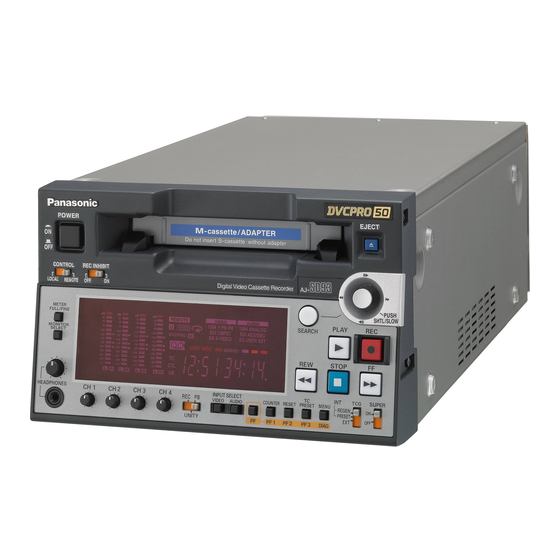
Digital Video Cassette Recorder
AJ-SD93P/E
AJ-D93MC
Analog Interface Board
AJ-YA93P
SDI Interface Board
AJ-YA94G
© 2004 Matsushita Electric Industrial Co., Ltd. All rights reserved.
Unauthorized copying and distribution is a violation of law.
ORDER NO. BSD04080160
D25
Advertisement
Chapters
Table of Contents

Related Manuals for Panasonic AJ-SD93P/E


Summary of Contents for Panasonic AJ-SD93P/E
- Page 1 Mechanical Adjustment Sec. 4 Electrical Adjustment Digital Video Cassette Recorder Sec. 5 Block Diagrams Sec. 6 Schematic Diagrams AJ-SD93P/E Sec. 7 Major Parts Location AJ-D93MC Analog Interface Board AJ-YA93P SDI Interface Board AJ-YA94G © 2004 Matsushita Electric Industrial Co., Ltd. All rights reserved.
- Page 2 Any attempt to service or repair the product or products dealt with in this service information by anyone else could result in serious injury or death. AJ-SD93P/E - 2 -...
- Page 3 - 3 -...
- Page 4 AJ-D93MC - 4 -...
- Page 5 - 5 -...
- Page 6 AJ-YA93P AJ-YA94G - 6 -...
- Page 7 SAFETY PRECAUTIONS GENERAL GUIDELINES ELECTROSTATICALLY SENSITIVE (ES) DEVICES 1. When servicing, observe the original lead dress. If a Some semiconductor (solid state) devices can be damaged short circuit is found, replace all parts, which have been easily by static electricity. Such components commonly are over-heated or damaged by the short circuit.
- Page 8 AJ-SD93P/E - 8 -...
- Page 9 - 9 -...
- Page 10 - 10 -...
- Page 11 AJ-YA93P AJ-YA94G - 11 -...
- Page 12 FCD0409NTKK145E466E467...
-
Page 13: Table Of Contents
SERVICE INFORMATION CONTENTS SERVICING FIXTURES & TOOLS ..................INF-1 ALIGNMENT TAPE ........................INF-4 2-1. VFM3580KM / KL (NTSC) (25M adjustment tape) ............INF-4 2-2. VFM3581KM / KL (NTSC) (Manufacturer (LISTA) adjustment tape) ......INF-4 2-3. VFM3582KM / KL (NTSC) (Manufacturer (X-value) adjustment tape) ......INF-4 2-4. -
Page 14: Servicing Fixtures & Tools
1. SERVICING FIXTURES & TOOLS PART NO. FIXTURE & TOOL NAME REMARKS VFK1145A Back Tension Meter VFK1149B Post Driver VFK71A Dial Torque Gauge (1.5 cN!m) 150 g VFK1191A Dial Torque Gauge (0.45 cN!m) 45 g VFK1152 Dial Torque Gauge Adapter VFK0357 Eccentric Screwdriver (1.5 mm) VFK1154... - Page 15 VFK1145A VFK1149B VFK71A VFK1152 Back Tension Meter Post Driver Dial Torque Gauge VFK1191A Adapter Dial Torque Gauge VFK0357 VFK1154 VFK1153 VFK1155 (REV/Silver) Mech. Neutral Plate Eccentric Screwdriver Post Height Fixture VFK1156 (PLAY/Black) (1.5 mm) VFK1208 (Neutral/Black with hole) Position Tool VFK0948A VFK1150A VFK1151...
- Page 16 VFM3580KM or KL VFM3380KM (NTSC) VFM3010EDS or EDL (NTSC) (NTSC) AJ-CL12MP VFM3680KM or KL (PAL) VFM3480KM (PAL) VFM3110EDS or EDL (PAL) VFM3581KM or KL DV Alignment Tape Cleaning Tape (NTSC) VFM3681KM or KL (PAL) DVCPRO50 (Color Bars) VFM3582KM or KL (NTSC) Alignment Tape VFM3682KM or KL (PAL)
-
Page 17: Alignment Tape
2. ALIGNMENT TAPE 2-1. VFM3580KM / KL (NTSC) (25M adjustment tape) TIME VIDEO PCM AUDIO (min.) Signal Purpose Signal Purpose Signal Purpose 0:00 Confirmation of Color bar the composite SMPTE(75%) Confirmation of video level 1KHz 0VU the cue level 7:00 Confirmation of Color bar the composite... -
Page 18: Vfm3000Eds / Edl (Ntsc/Pal) (Dv (Lista) Adjustment Tape)
2-6. VFM3000EDS / EDL (NTSC/PAL) (DV (LISTA) adjustment tape) TIME VIDEO PCM AUDIO (min.) Signal Purpose Signal Purpose Signal Purpose Adjustment of LISTA signal ----- ----- ----- ----- 0:00 the linearity 2-7. VFM3680KM / KL (PAL) (25 M adjustment tape) TIME VIDEO PCM AUDIO... -
Page 19: Vfm3110Eds / Edl (Pal) (Dv Adjustment Tape)
2-11. VFM3110EDS / EDL (PAL) (DV adjustment tape) TIME VIDEO PCM AUDIO (min.) Signal Purpose Signal Purpose Signal Purpose 0:00 Color bar EQ adjustment 1,102.5KHz ----- ----- 3. LIST OF RECOMMENDED MEASURING INSTRUMENTS MODEL NO. (Example) NAME REMARK NTSC analog composite & component signal generator TSG130A (NTSC) *1(opt.05) (with CF OUT) PAL analog composite &... -
Page 20: Maintenance
4. MAINTENANCE 4-1. Maintenance Schedule Maintenance is done by periodically performing suitable maintenance servicing in order to maintain the functions always in best condition, so that the user can use the equipment safely. Video equipment with mounted mechanisms wear parts, and their wear and deterioration cause troubles. Dust and dirt also can impair stable operation. -
Page 21: Layout Of The Maintenance Parts
4-2. Layout of the Maintenance Parts 3. Cleaning Arm Unit 9. T1 Boat Unit 13. Loading Motor (1) Arm Unit 7. Mode SW Unit 12. A/C Head 1. Cylinder Unit 20. Main Cam Gear 19. Cleaner Solenoid 15. Pinch Solenoid 21. -
Page 22: Manual Tape Eject (Emergency Eject)
5. MANUAL TAPE EJECT (Emergency Eject) When a tape can not be ejected by normal operation due to a problem, the tape can be removed manually as follows. Turn off power and remove the top Case Unit. Repeat item 2 and 3 until the tape wound up Rotate the red plastic screw with a Phillips-head completely inside of the cassette. -
Page 23: Cleaning Method
6. Cleaning Method Note: Turn the power OFF during cleaning. Make sure the power is OFF before cleaning. Use ethanol (more than 99% purity) as cleaning liquid. 6-1. Cylinder Head Cleaning Method: (Daily) 1. Turn power off. 6-4. Pinch Roller and Capstan Shaft 2. -
Page 24: Software Version Display
7. SOFTWARE VERSION DISPLAY 7-1. SOFTWARE and PLD VERSION are displayed on the VIDEO SUPER OUT (Monitor TV) and FRONT DISPLAY. 7-1-A. Michrocomputer Software Version on Front Display Turn on the VTR power. Place the unit in the EJECT mode and then press the “PLAY” and “STOP” buttons together so that the Software Version of the SYSTEM CONTROL (SY) is displayed on the Front Display. - Page 25 7-1-C. PLD Software Version Display Perform the previous steps and display the Version of the Microcomputer Software. Press the SERCH button so that the Software of the PLD (FPG) is displayed as shown below. MONITOR TV SOFTWARE FRONT DISPLAY DIAG-MENU PLD VERSION SERVO SV 4319A...
-
Page 26: Error Rate Display
8. ERROR RATE DISPLAY Condition : 1) Set to Service menu. Set the TCG SW to INT REGEN or INT PRESET. The error rate is displayed on the AUDIO LEVEL METER in the Service menu mode. (When enters in the Service menu mode, the AUDIO LEVEL METER changes into the error display mode automatically.) The error rate is displayed and measured on the AUDIO DVCPRO 50... - Page 27 DVCPRO50/DVCPRO25 ATF HEAD TCG SW CH 1 CH 2 CH 3 CH 4 INT REGEN PBL1 VIDEO PBL2 VIDEO PBR1 VIDEO PBR2 VIDEO INT PRESET PBL1 AUDIO PBL2 AUDIO PBR1 AUDIO PBR2 AUDIO INT REGEN RPL1 VIDEO RPL2 VIDEO RPR1 VIDEO RPR2 VIDEO INT PRESET RPL1 AUDIO...
-
Page 28: Diag Menu Display
9. DIAG MENU DISPLAY The DIAG-MENU is the menu for investigating the status of the VTR, and it has the indicated information. • Warning display (WARNING information) • Hour meter display (HOUR METER information) • UMID display (UMID information) • DIF status display (DIF STATUS 1 and 2 information) Press the “DIAG”... - Page 29 << Hours Meter Reset Procedure >> Press the “EJECT” + “STOP” and “PF” + “MENU” buttons on the Front Panel simultaneously so that the display shows the “HOURS METER” as shown below. Then move the cursor (*) to the item with “r” to be reset. Press the “RESET”...
-
Page 30: Tp & Main Signal For Tape Path Confirmation
10. TP & MAIN SIGNAL FOR TAPE PATH CONFIRMATION TP6302 R/P-L or PB-L ENVELOPE Signal (RF/CUE Board) TP233 R/P-L-HSW Signal (SERVO Board) Figure 10-1 TP6502 R/P-R or PB-R ENVELOPE Signal (RF/CUE Board) TP235 P/R-R-HSW Signal (SERVO Board) Figure 10-2 TP6302 R/P-L or PB-L ENVELOPE Signal (RF/CUE Board) TP233... - Page 31 RF/CUE Board TP4102 TP6302 TG6001 TP6502 (COMPONENT SIDE) SERVO Board TP233 TP235 (COMPONENT SIDE) INF-18...
-
Page 32: Internal Switch Setting
11. INTERNAL SWITCH SETTING The switch setting on the AVIO board (part of AJ-YA93) is as shown below. INF-19... -
Page 33: Software Version Upgrade Method
Soft. & Tool Board cture Software Procedures 1. Flash CPLD ALTERA IP250 P250 VSI4319 12-2-5 Memory F1 : Version-up SERVO Microcomputer Panasonic IP150 P151 Tool VSI4318 12-2-3 FLASH (VFK1304A) F2 : AVMON FPG ALTERA IC3200 VSI4323 12-2-4 2. Version-up AVMON Software... -
Page 34: Flash Rom / Fpg Software Version Upgrade Procedure
F4: AVIO Board (AJ-YA93G) F5: SDI Board (AJ-YA94) IC255 IC3400 Figure 12-1A-3 12-2. Flash ROM / FPG Software Version Upgrade Procedure Connect the VTR with personal computer by RS232C cable (Cross cable) and Flash Memory Version-up Tool (VFK1304A) as shown below. RS-232C CROSS CABLE TO THE CONNECTOR ON TEH SERVO OR DPROC... - Page 35 3. Connection Connect the Flash Memory Version Up Tool (VFK1304A) with Personal Computer (MS-DOS, Windows 95® or 98®) by RS-232C cross cable as shown in figure 12-2A-1. Connect the flexible cable from the Flash Memory Version Up Tool to the connector on the board to be version upgraded as shown in table 12-1 and figure 12-2A-1.
- Page 36 6. Press “OK” button so that the following screen appears and check sum is calculated. 7. Press “Start” button so that the software programming will start. Click “Start” button Figure 12-2B-2 Confirm the bar in the Process window reach to 100% that means the software programming complete as shown in figure 9-1B-3.
- Page 37 12-2-3. Microcomputer Flash ROM Version Upgrade Procedure (2) <SERVO Microcomputers (SERVO Board)> 1. Turn on the VTR power. 2. Copy the program software for the SERVO and SYS_IF as shown in the table 12-1 into the personal computer. 3. Execute the VSI2312N. exe so that the following screen appears. 4.
- Page 38 6. Press “OK” button so that the following screen appears. Note: The check sum is not calculated for the SERVO microcomputer. Figure 12-2C-3 7. Click “Start” button as shown in figure 9-1C-3 so that the following comment appears in the MS DOS screen. Do you continue? Y/N>...
- Page 39 8. Select “Y” and press “Enter”, then the program will start. Figure 12-2C-5 9. The screen display of MS-DOS changes to Windows screen after the programming complete. 10. Press “Exit” button to end the program. 11. Turn the power of the VTR off and then on. This will reboot the VTR. 12.
- Page 40 12-2-4. PLD (FPG) Version Upgrade Procedure 1. Turn on the VTR power. 2. Copy the program software for the AVMON, AVPROC, DVPROC, D-IF, AVIO and SDI as shown in the table 12-1 into the personal computer. 3. Execute the VSI2312N. exe so that the following screen appears. 4.
- Page 41 Click “Start” button Click “Exit” button Confirm “100%” Figure 12-2D-3 9. Click “Exit” button to end the program. * If the error occurs during above process, repeat the process from step 7 again. 10. Turn off and on the power of VTR in order to reboot the machine. 11.
- Page 42 12-2-5. PLD Version Upgrade Procedure [SERVO IC] This Model uses PLD on the SERVO Board. At the time of a version upgrade, use the special tool, connect to PLD Connector on the SERVO Board, and use the PLD writing software as shown table 12-1A-1. 1.
- Page 43 On main window, select tab “MAX+plus II” and then “Programmer”. On main window (Programmer window is displayed), select tab “Option” and then “Hardware Setup”. On Hardware Setup dialog, set the “Hardware Type” to “Byte Blaster (MV) ”. Figure 12-2E-4 On main window, select tab “JTAG”, and then select “Restore JCF…”. Select the floppy drive and then, select the “jcf format file (***.jcf) on dialog box of Restore JCF”...
- Page 44 If the following message appeared, Press “Yes” button. Figure 12-2E-6 Click the “Program” button on Programmer dialog. When Progress Bar reaches at point of 100, the message “Programming Complete” appears, then PLD version upgrade is completed. Click “OK” button on the Programming complete message Dialog.
-
Page 45: Service Menu
13. SERVICE MENU 13-1. Service Menu Operation Method Confirm that the “REMOTE/LOCAL” switch on the front panel is set to the “LOCAL”. Press the “MENU” button on the front panel to display the “SETUP-MENU”. When the “SETUP-MENU” is displayed, press the “MENU” button while pressing the “EJECT” button and the “STOP”... -
Page 46: Default Operation
13-2. DEFAULT Operation * RF adjustment (B00) The VTR have two memory area for the adjustment value as indicated below. SAVE MEM1 MEM2 (FACTORY) LOAD MEM 2 has factry adjustment value. MEM 1 is always renewed in accordance with the adjustment value on the RF and EQ adjustment menu. * Operating procedures Move the cursor “... -
Page 47: Service Menu Contents
13-3. Service Menu Contents A00: SERVO ADJUST Item Set value Setting contents and BACK Remarks SUPER SUPER outline function explanation DISP. DISP. A02 RL GAIN ADJ T REEL Automatic adjustment of the reel torque of the S/T-Reel. S REEL A03 T TORQUE -128 -128 Compensation of the T-reel driver offset value... - Page 48 Item Set value Setting contents and BACK Remarks SUPER SUPER outline function explanation DISP. DISP. A11 X VALUE 25 -128 -128 Electrical fine adjustment of the X-value A12 RPL GAIN 50 -128 -128 LISTA sensitivity adjustment for RPL1/RPL2 head A13 RPL LIN 50 Non- Adjustment of the Lista linearity for RPL1/RPL2 head display...
- Page 49 B00: RF ADJUST RF ADJUST sub-screen Item Item contents SUPER DISP. P00 DVCPRO 50M ADJUST Adjustment for DVCPRO50 (50 Mbps) Q00 DVCPRO 25M ADJUST Adjustment for DVCPRO (25 Mbps) R00 DV ADJUST Adjustment for DV DVCRRO 50M ADJUST sub-screen Item Item contents SUPER DISP.
- Page 50 DV ADJUST sub-screen Item Item contents SUPER DISP. RP ADJUST Adjustment of the playback system (RP head) for DV DEFAULT LOAD/SAVE of the factory default adjustment values/initial values LOAD operation • Perform operation in regard to the adjustment values for DV. Operation: 1.
- Page 51 REC ADJUST (DVCPRO 50M ADJUST, DVCPRO 25M ADJUST subscreen) Item Set value Setting contents and BACK Remarks SUPER SUPER outline function explanation DISP. DISP. REC CURR L1 Adjustment of the RP L1 head recording current Use for electrical adjustment -128 -128 -128 -128...
- Page 52 Item Set value Setting contents and BACK Remarks SUPER SUPER outline function explanation DISP. DISP. EQ STB ON/OFF setting for the automatic standby detection function Factory use only Automatic standby detection function: When the playback envelope is not detected for several seconds, the mode automatically shifts to standby mode (the mode where playback processing is stopped and the VCO center frequency is adjusted automatically).
- Page 53 PB ADJUST (DVCPRO 50M ADJUST, DVCPRO 25M ADJUST sub-screen) Item Set value Setting contents and BACK Remarks SUPER SUPER outline function explanation DISP. DISP. -128 -128 Adjustment of the L1 head playback phase PHS L1 Use for electrical adjustment -128 -128 Adjustment of the L2 head playback phase PHS L2...
- Page 54 Item Set value Setting contents and BACK Remarks SUPER SUPER outline function explanation DISP. DISP. FLT SEN The detection sensitivity for the fault detection function is set in four Factory use only levels. A fault status is detected when a status where a normal signal can Do not change any setting not be detected consecutively for 5 tracks over the following track values.
- Page 55 Item Set value Setting contents and BACK Remarks SUPER SUPER outline function explanation DISP. DISP. The initial values for six of the seven tap coefficients of the adaptive T L1 3A equalization filter, excluding the fixed center tap, are set for the L1 Use for electrical adjustment head.
- Page 56 Item Set value Setting contents and BACK Remarks SUPER SUPER outline function explanation DISP. DISP. The initial values for six of the seven tap coefficients of the adaptive T R1 1B equalization filter, excluding the fixed center tap, are set for the R1 Use for electrical adjustment head.
- Page 57 Item Set value Setting contents and BACK Remarks SUPER SUPER outline function explanation DISP. DISP. ON/OFF setting for the automatic standby detection function EQ STB Factory use only Automatic standby detection function: When the playback envelope is not detected for several seconds, the mode automatically shifts to standby mode (the mode where playback processing is stopped and the VCO center frequency is adjusted automatically).
- Page 58 RP ADJUST (DVCPRO 50M ADJUST, DVCPRO 25M ADJUST, DV ADJUST sub-screen) Item Set value Setting contents and BACK Remarks SUPER SUPER outline function explanation DISP. DISP. -128 -128 Adjustment of the L1 head playback phase AGC LEV L1 Use for electrical adjustment -128 -128 Adjustment of the L2 head playback phase...
- Page 59 Item Set value Setting contents and BACK Remarks SUPER SUPER outline function explanation DISP. DISP. FLT SEN The detection sensitivity for the fault detection function is set in four Factory use only levels. A fault status is detected when a status where a normal signal can Do not change any setting not be detected consecutively for 5 tracks over the following track values.
- Page 60 Item Set value Setting contents and BACK Remarks SUPER SUPER outline function explanation DISP. DISP. T L1 2A • Read-out is possible only at the time of PLAY, REC. Use for electrical adjustment Operation: • At the time of P53, Q53: IC READ = SINGLE Read-out and display are performed each time the SET T L1 1A button is pressed.
- Page 61 Item Set value Setting contents and BACK Remarks SUPER SUPER outline function explanation DISP. DISP. T R1 1B Use for electrical adjustment T R1 2B Use for electrical adjustment T R1 3B Use for electrical adjustment The initial values for six of the seven tap coefficients of the adaptive T R2 3A Use for electrical adjustment equalization filter, excluding the fixed center tap, are set for the R2...
- Page 62 Item Set value Setting contents and BACK Remarks SUPER SUPER outline function explanation DISP. DISP. ON/OFF setting for the automatic standby detection function EQ STB Factory use only Automatic standby detection function: When the playback envelope is not detected for several seconds, the mode automatically shifts to standby mode (the mode where playback processing is stopped and the VCO center frequency is adjusted automatically).
- Page 63 F00: VIDEO ADJUST Item Set value Setting contents and BACK Remarks SUPER SUPER outline function explanation DISP. DISP. F03 VIDEO MUTE NORMAL This menu is only for Factory use. MUTE Select whether the VIDEO output is to be made gray or not 0:Normal output 1:Forced gray output F10 TELETEXT INI...
- Page 64 H00: OTHER ADJUST Item Set value Setting contents and BACK Remarks SUPER SUPER outline function explanation DISP. DISP. H01 STILL LIMIT 2 min Set the maximum value of the "SETUP-MENU 400 : STILL TIMER". 6 min Decide whether the still timer should be reset when the STANDBY-ON command is received during the STOP mode.
-
Page 65: Error Messages
14. ERROR MESSAGES INF-52... - Page 66 INF-53...
- Page 67 INF-54...
- Page 68 INF-55...
-
Page 69: Node Unique Id (Uid)
<Important Note> The UID number should not be changed from the original one. If the original UID number is needed, contact Panasonic Service Engineering. 1. Connect the Flash memory version up tool (VFK1304A) and RS-232C Straight Cable between the connector (P1802) on the DPROC Board and personal computer as shown below. - Page 70 5. Start up the Hyper Terminal of Windows 95/98 on the personal computer. (Programs of Windows → Accessories → Hyper Terminal → Hypertrm.exe) Name the Hyper Terminal "1394", and select an icon. Select the connection method. (Connecting using: Direct to COM*) Perform settings of the Port.
-
Page 71: Circuit Board Layout Drawing
16. CIRCUIT BOARD LAYOUT DRAWING MECHA I/F 1 Board MECHA I/F 2 Board POWER 1 Board POWER 2 Board (F1) SERVO Board (F2) AVMON Board (F3) DPROC Board / 1394 MODULE Board (F4) AVIO Board (AJ-YA93) OPT JACK Board (AJ-YA93) STD JACK Board (F5) SDI Board (AJ-YA94G)... - Page 72 DISASSEMBLY PROCEDURES CONTENTS 1. Disassembly Procedures ......................DIS-1 1-1. Top Panel Removal......................DIS-1 1-2. Front Panel Removal......................DIS-1 1-3. Bottom Case removal.....................DIS-1 1-4. Front Loading Unit Removal ..................DIS-1 1-5. Rear Panel Removal ......................DIS-2 1-6. MECHA IF 3 Board Removal ..................DIS-3 1-7. Power Supply Unit Removal ..................DIS-3 1-8.
-
Page 73: Disassembly Procedures
1. Disassembly Procedures 1-3. Bottom Case removal Unscrew the 4 screws (D) and 4 screws (E). 1-1. Top Panel Removal Remove the Bottom Case. Loosen the 2 screws (A) and remove the Top Case. 1-4. Front Loading Unit Removal 1-2. Front Panel Removal Disconnect the 2 connectors (To the Loading Unscrew the 4 screws (B). -
Page 74: Rear Panel Removal
Unscrew the four screws (F) and (G), and then slowly lift up the Front Loading Unit. Pulling back the OPTJACK Board Unit and remove Note: The OPTJACK has been connected with the MOTHER board by connectors as shown below. 1-5. Rear Panel Removal Unscrew the 2 screws (H) and remove the Boards Connectors support plate. -
Page 75: Mecha If 3 Board Removal
1-6. MECHA IF 3 Board Removal 1-8. Power Supply Unit Disassembly 1. Unscrew the screw (N). 2. Slide the MECHA IF 3 Board in the direction of the 1. Unscrew the 6 screws (Q) and then remove the side arrow and remove it.. cover. -
Page 76: Mechanism Chassis Unit Removal
1-9. Mechanism Chassis Unit Removal Disconnect the 3 connectors (P6202, P6201, and P4001). Unscrew the 3 screws (T) and then temporary remove the RF/CUE Board. Remove the Front Loading Unit according to the paragraph “1-4. Front Loading Unit Removal” RF/CUE Board P6202 P6201 P4001... - Page 77 MECHANICAL ADJUSTMENT CONTENTS NAME OF TAPE TRANSPORTATION ................. MECH-1 TABLE OF TEST POINT ....................... MECH-2 2-1. Table of Test Point, VR, Setting for Service Menu ........... MECH-2 MECHANICAL ADJUSTMENT PROCEDURES ..............MECH-3 3-1. Post Height Pre-adjustment..................MECH-3 3-2. Tension Arm Adjustment Flowchart................MECH-3 3-3.
- Page 78 MAJOR MECHANICAL PARTS REPLACEMENT & ADJUSTMENT PROCEDURES ..MECH-40 5-1. Cylinder Unit Replacement ..................MECH-40 5-2. Cleaning Arm Unit Replacement................MECH-41 5-3. T1 Guide Position Adjustment ..................MECH-41 5-4. Adjustment Flow Chart After Cylinder Unit Replacement .........MECH-42 5-5. Supply & Take-up Reel Rotor Unit Replacement .............MECH-43 5-6.
-
Page 79: Name Of Tape Transportation
1. NAME OF TAPE TRANSPORTATION Cylinder Unit T1 Post S1 Post T2 Post S2 Post A/C HEAD T3 Post S3 Post 21.7mm Capstan shaft S4 Post T4 Post S5 Post Mini-DV DVCPRO (M) DVCPRO (L) :VFK1149B (Post Driver) :VFK1151 (Nut Driver) NAME LIMIT S1 Post... -
Page 80: Table Of Test Point
2. TABLE OF TEST POINT 2-1. Table of Test Point, VR, Setting for Service Menu <Table of Test Point, VR> Name TP & VR [ Tension Arm Adjustment ] TENSION SERVO (F) : TP201 TENSION OFFSET MECHA I/F : VR1 TENSION GAIN MECHA I/F : VR2... -
Page 81: Mechanical Adjustment Procedures
3. MECHANICAL ADJUSTMENT PROCEDURES 3-1. Post Height Pre-adjustment Post Post Driver MODE EJECT (POWER OFF) S4 & S5 Post VFK1149B TOOL VFK1149B (Post Driver) T3 & T4 Post VFK1151 VFK1151 (2.5mm Nut Driver) VFK1154 (Post Height Fixture) VFK1153 or VFK1586 Post Limit (Mech. -
Page 82: Tension Sensor Voltage Adjustment (1)
<Adjustment Procedure> 3-3. Tension Sensor Voltage Open the SERVICE MENU. Select the A00: SERVO ADJUST and press the Adjustment (1) “SET” button to open the SERVO ADJUST MENU. SPEC. 2.5V ± 0.05V Select the A09 TENSION. TEST POINT TP201 (SERVO) Install the VFK1208 (black with hole) as shown in ADJ. -
Page 83: Tension Arm Play And Rev Voltage Confirmation
3-5. Tension Arm PLAY and REV 3-6. Tension Regulator Spring Voltage Confirmation Adjustment SPEC PLAY : 3.8 V ± 0.05 V SPEC 110 ± 10 mN-m (11 ± 1gf) REV : 1.2 V ± 0.3 V TEST POINT TP201 (SERVO) TEST POINT TP201 (SERVO ) ADJ. -
Page 84: Rev Tension Confirmation
3-7. REV Tension Confirmation SPEC 180mN ± 20mN (18gf ± 2gf) TEST POINT TP201 (SERVO) MODE STOP TOOL VFK1188A (Dial Tension Gauge) Digital Volt Meter <Preparation> Loosen the 2 screws and remove the Carriage Support Panel on the Front Loading Unit. Disconnect the connector P3 on the Carriage Board of the Front Loading Unit. -
Page 85: Tension Confirmation
3-8. Tension Confirmation Play back the beginning portion of the tape. Insert the tension meter between S3 post and S4 post as shown in figure 3-8-2. SPEC PLAY : 0.06N ± 0.01N (6gf ± 1gf) Confirm that the tension value is within the REV : 0.09N ±... -
Page 86: Photo Sensor Voltage Adjustment
3-9. Photo Sensor Voltage Adjustment SPEC 2.2 ± 0.6 (V DC) TEST POINT <SERVICE-MENU : SERVO> The voltage is displayed on the Service menu. A07 : T PHOTO A08 : S PHOTO ADJ. T PHOTO VR201 (MECHA I/F) S PHOTO VR202 (MECHA I/F) MODE STOP TAPE... -
Page 87: Tape Path Adjustment Procedure
3-10. Tape Path Adjustment Procedure START Each Post Limit Conf. and A/C Head Adj. 3-11. Envelope Waveform Adj. 3-22. PLAY Tape Path Limit Conf. 3-12. Post Limit Confirmation (PLAY) S4 Post Conf. 3-23. Conf. of ENV on 3-14. A/C Head Tilt Adjustment REV/REW FF mode 3-15. -
Page 88: Envelope Waveform Adjustment
3-11. Envelope Waveform 3-12. Post Limit Confirmation Adjustment (PLAY) SPEC V1/Vmax, V2/Vmax, V3/Vmax ≥ 0.8 SPEC Post limit is shown in the following table. Curl should not appear on tape edge TEST TP6302 (RF/ CUE) MODE PLAY POINT TAPE Blank tape ADJ. -
Page 89: A/C Head Adjustment Method (General)
3-13. A/C Head Adjustment Method (General) Adjustment SCREW Adjustment Method Torque item Tilt adjustment !. Adjust screw A after loosening screw G. Tightened direction : Decrease Cue level Loosened direction : Increase Cue level None ". Tighten screw G after finishing the adjustment of screw A. (refer to following item “Azimuth adjustment &... - Page 90 For Tilt and Azimuth adjustment, loosen the screw Confirm the screw (A) isn’t loose, before perform (G) first and tighten the screw (G) after finish A/C Head Tilt adjustment. The screw (A) should adjustment. And if need to turn the screw (A) and be always touch to top of A/C Head.
-
Page 91: A/C Head Tilt Adjustment
3-14. A/C Head Tilt Adjustment 3-15. A/C Head Height Adjustment SPEC SPEC Curl should not appear on tape edge. CUE : A=A max CTL : C1, C2 ≥ 1.8V Lower limit at T3 post ADJ. TEST SCREW A, G (A/C Head) CUE AUDIO : TP4102 (RF/CUE) POINT MODE... -
Page 92: A/C Head Tilt Confirmation
3-16. A/C Head Tilt Confirmation 3-17. A/C Head Height Confirmation SPEC A/Amax ≥ 0.8 TEST CUE AUDIO : TP4102 (RF/CUE) SPEC CUE : A=A max POINT CTL : C1, C2 ≥ 1.8V ADJ. SCREW A, G (A/C Head) TEST CUE AUDIO : TP4102 (RF/CUE) MODE POINT PLAY... -
Page 93: A/C Head Azimuth And X-Value Adjustment
3-18. A/C Head Azimuth and X-value Adjustment SPEC TEST ENV R/P L TP6302 : RF/CUE POINT HSW R/P L TP233 : SERVO 25M mode : -250µs ≤ t1, t2 ≤ +250µs TP4102 : RF/CUE 50M mode : -125µs ≤ t1, t2 ≤ +125µs TP30 : SERVO M. -
Page 94: Compensation Adjustment Of X Value
3-19. Compensation Adjustment of (VTR mode) X Value Mode [ PLAY (+1) ] SPEC A10 : X VALUE 50 → 0 ± 27 PLAY on 25M mode A11 : X VALUE 25 → 0 ± 27 [ REV (-1) ] TEST ----- SHTL ×... -
Page 95: Ctl Self Recording Level Confirmation
3-21. CTL Self Recording Level Confirmation TEST POINT TP30 : SERVO ADJ. T4 post height MODE PLAY, REV×1, REV×0.2 TAPE Blank Tape M cassette 66 min M.EQ Oscilloscope (Specification for confirmation) CTL Output Level : C1, C2 Figure 3-21-1 PLAY 1. -
Page 96: Confirmation Of Envelope On Rev, Rew And Ff Mode
3-23. Confirmation of Envelope on 3-24. Confirmation of Play Start REV, REW and FF mode Envelope SPEC SPEC See Figure 3-23-1 Envelope Waveform signal should be TEST POINT rising up immediately at PLAY mode. See below TEST POINT MODE Refer to Table 3-23-1 on previous item REV, REW, FF “3-23. -
Page 97: Rev Mode Tape Path Limit Confirmation
Tape Limit 3-25. REV mode Tape Path Limit Post Name (Refer to figure 3-25-1) Confirmation S5 Post S4 Post SPEC Each post limit shown in below figure (Tension Post) MODE S1 Post TAPE NTSC : VFM3580KM or VFM3580KL T1 Post T3 Post (PAL : VFM3680KM or VFM3680KL) T4 Post... -
Page 98: Confirmation Of Tape Damage For Long Tape Playback
3-28. Confirmation of Tape Damage for Long Tape Playback <Confirmation procedure> Item Confirmation Specification mode ×0.5 speed Tape Tape damage should not occur (step slow) Damage ! on tape at lower limit of T3 and T4 post. <Tape> Long time L cassette: thin tape (AJ-5P92LP : recorded tape) Tape... -
Page 99: Lista Adjustment Procedure
3-29. LISTA Adjustment Procedure Procedure START Connection & Boo Up Sensitivity Adj. R/P Head Sensitivity Adj. R/P Head (50M mode) (25M mode) Sensitivity Adjustment Sensitivity Adjustment Sensitivity Detection Sensitivity Detection Linearity Adjustment Linearity Adjustment (50M mode) (25M mode) Linearity Adjustment Linearity Adjustment Waving Measurement Waving Measurement... -
Page 100: Lista Connection And Boot Up
3-30. LISTA Connection and Boot Up TEST ATF ERROR R/P-L TP6701 RF/CUE POINT R/P-R TP6801 RF/CUE PB-L TP6701 RF/CUE TRIGGER (H SW) R/P-L TP233 SERVO (F1) R/P-R TP235 SERVO (F1) PB-L TP232 SERVO (F1) M. EQ. PC (Personal Computer) (A/D board should be installed) TAPE NTSC : VFM3581KM or VFM3581KL (LISTA), VFM3000EDS (DV LISTA) (PAL : VFM3681KM or VFM3681KL (LISTA), VFM3000EDS (DV LISTA)) - Page 101 Select the Serial number of the Alignment tape on the screen. If LISTA software does not have alignment tape data registered, data entry is needed. Press the ESC key, then main menu is displayed on the screen. And select the item “<4> Alignment Tape” to enter the data on the attachment sheet which is enclosed with alignment tape.
-
Page 102: How To Enter The Attachment Data Of Alignment Tape
3-31. How to Enter the Attachment Data of Alignment Tape Select the item “<4> Alignment Tape” on the LISTA main menu. Select the item “<2> ENTRY” on the “alignment Tape” menu. After the screen of <<Alignment Tape Data Entry>>is displayed, first input the Serial Number of Alignment tape printed on the label. -
Page 103: Rp Head Sensitivity Adjustment And Sensitivity Detection (25M Mode)
3-32. RP Head Sensitivity Adjustment and Sensitivity Detection (25M Mode) SPEC. Sensitivity 100±10 (mV/µm) TEST POINT ! ATF (R/P-L) TP6701 RF/CUE " H SW (R/P-L) TP233 SERVO (F1) # GND TG6001 RF/CUE VTR MODE PLAYBACK ADJUSTMENT SERVO Adjustment Menu: “A14 : RPL GAIN 25” TAPE NTSC: VFM3581KM or VFM3581KL (PAL: VFM3681KM or VFM3681KL) - Page 104 Adjust within specification Sens. Value : 101.58mV/um Sens. 1 : 104.72mV/um Sens. 2 : 98.44mV/um Figure 3-32-3 Confirm this value Figure 3-32-4 MECH-26...
-
Page 105: Lista Linearity Adjustment And Waving Measurement (25M Mode)
3-33. LISTA Linearity Adjustment and Waving Measurement (25M mode) SPEC. Linearity : less than 3 µ m, Waving : less than 1.5 µ TEST POINT ! ATF (R/P-L) TP6701 RF/CUE " H SW (R/P-L) TP233 SERVO (F1) # GND TG6001 RF/CUE VTR MODE PLAYBACK ADJ. - Page 106 Waving Measurement Procedures Press “SPACE” key to perform the Peak Hold in 30 seconds when linearity is displayed. After finishing the Peak Hold, press “SHIFT” and “ } ” key simultaneously on the Key Board, then the numerical values of “Linearity” and “Waving” is displayed on left lower portion of screen. And confirm the numerical values are in the specification.
-
Page 107: Pb Head Lista Sensitivity Adjustment And Sensitivity Detection (25M Mode)
3-34. PB Head LISTA Sensitivity Adjustment and Sensitivity Detection (25M Mode) SPEC. Sensitivity 100±10 (mV/µm) MODE SERVO Adjustment Menu “A17 : PBL GAIN 25” TEST POINT ! ATF (PB-L) TP6701 RF/CUE " H SW (PB-L) TP232 SERVO (F1) # GND TG6001 RF/CUE ADJUSTMENT SERVO Adjustment Menu: “A17 : PBL GAIN 25”... - Page 108 Adjust within specification Sens. Value : 101.58mV/um Sens. 1 : 104.72mV/um Sens. 2 : 98.44mV/um Figure 3-34-3 Confirm this value Figure 3-34-4 MECH-30...
-
Page 109: Rp Head Sensitivity Adjustment And Sensitivity Detection (50M Mode)
3-35. RP Head Sensitivity Adjustment and Sensitivity Detection (50M Mode) SPEC. Sensitivity 100±10 (mV/µm) TEST POINT ! ATF (R/P-L) TP6701 RF/CUE " H SW (R/P-L) TP233 SERVO (F1) # GND TG6001 RF/CUE VTR MODE PLAYBACK ADJUSTMENT SERVO Adjustment Menu: “A12: RPL GAIN 50” TAPE NTSC: VFM3581KM or VFM3581KL(LISTA) (PAL: VFM3681KM or VFM3681KL(LISTA)) - Page 110 Confirm this value Figure 3-35-2 MECH-32...
-
Page 111: Lista Linearity Adjustment And Waving Measurement (50M Mode)
3-36. LISTA Linearity Adjustment and Waving Measurement (50M mode) SPEC. Linearity : less than 3 µ m, Waving : less than 1.5 µ TEST POINT ! ATF (R/P-L) TP6701 RF/CUE " H SW (R/P-L) TP233 SERVO (F1) # GND TG6001 RF/CUE VTR MODE PLAYBACK ADJ. - Page 112 Waving Measurement Procedures 1. Press “SPACE” key to perform the Peak Hold in 30 seconds when linearity is displayed. 2. After finishing the Peak Hold, press “SHIFT” and “ } ” key simultaneously on the Key Board, then the numerical values of “Linearity”...
-
Page 113: Pb Head Lista Sensitivity Adjustment And Sensitivity Detection (50M Mode)
3-37. PB Head LISTA Sensitivity Adjustment and Sensitivity Detection (50M Mode) SPEC. Sensitivity 100±10 (mV/µm) MODE SERVO Adjustment Menu “A17 : PBL GAIN 25” TEST POINT ! ATF (PB-L) TP6701 RF/CUE " H SW (PB-L) TP232 SERVO (F1) # GND TG6001 RF/CUE ADJUSTMENT SERVO Adjustment Menu: “A16 : PBL GAIN 50”... - Page 114 Confirm this value Figure 3-37-2 MECH-36...
-
Page 115: Rp Head (For Dv) Lista Sensitivity Adjustment
3-38. RP HEAD (for DV) Lista Sensitivity Adjustment SPEC. Sensitivity: 130±30 (mV/µm) VTR MODE PLAYBACK TEST POINT ! ATF (R/P-R) TP6801 RF/CUE " H SW (R/P-R) TP235 SERVO (F1) # GND TG6001 RF/CUE ADJUSTMENT SERVO Adjustment Menu: “A18: RPR GAIN DV” TAPE VFM3000EDS Set the LISTA software in 50M Mode. - Page 116 Adjust within specification Sens. Value : 130.83mV/um Sens. 1 : 132.12mV/um Sens. 2 : 129.55mV/um Figure 3-38-3 Confirm this value Sensitivity : 130.83 (mV/um) Sens. 1 132.12 (mV/um) Sens. 2 129.66 (mV/um) Figure 3-38-4 When the picture is appeared as shown in figure 3-38-3, adjust ATF Gain (A18: RPR GAIN DV) so that the “Sens.
-
Page 117: Self-Rec/Play Envelope Waveform Confirmation
3-39. Self-REC/PLAY Envelope Waveform Confirmation All of the head output are within the specification as shown below. Confirm in the 50M mode. ⋅ When using the M Cassette (66 min.) or L Cassette (126 min.) ≥ V1/Vmax, V3/Vmax SPEC. ≥ V2/Vmax ⋅... -
Page 118: Major Mechanical Parts Replacement & Adjustment Procedures
5. MAJOR MECHANICAL PARTS REPLACEMENT & ADJUSTMENT PROCEDURES When mechanical parts are replaced, pay attention to the following notes. 1. Always turn power off before replacing any parts. 2. If any adjustment is required after replacing parts, perform the required adjustment. 3. -
Page 119: Cleaning Arm Unit Replacement
5-3. T1 Guide Position Adjustment 5-2. Cleaning Arm Unit Replacement 1. Place the unit to loading condition without the tape. 2. Observe the clearance (B) between T1 Guide and (Removal) T1 post as shown in Figure 5-3-1, and make sure 1. -
Page 120: Adjustment Flow Chart After Cylinder Unit Replacement
5-4. Adjustment Flow Chart After Cylinder Unit Replacement Note: PG Shifter Adjustment After change the Cylinder Unit, please perform the adjustment and confirmation as following flow 3-29. LISTA Adjustment Procedure chart. START Mechanical Adjustment (Section 3) 3-30. LISTA Connection and Boot-up 3-8. -
Page 121: Supply & Take-Up Reel Rotor Unit Replacement
NOTE: 5-5. Supply & Take-up Reel Rotor Confirm the groove position of Reel Base, and then Unit Replacement insert the pin of Drive Arm Unit into it. (Installation) Install the Reel Outer Rail to New Supply and (Removal) Take Up Reel Rotor Unit. Disconnect the P34 and P35 on the MECH I/F. -
Page 122: Main Brake Torque Confirmation
5-6. Main Brake Torque 5-7. Supply & Take-up Brake Arm Confirmation Unit Replacement (Removal) TEST S Reel, T Reel Press the iron core of Brake Solenoid to release MODE EJECT (Power OFF) the Brake. TOOL Torque Gauge (VFK71A, VFK1191A) Remove the cut washers (A) and remove the Torque Gauge Adapter (VFK1152) supply and Take Up Brake Arm Unit as shown in ADJUSTMENT SPECIFICATION... -
Page 123: Take-Up Brake Solenoid Replacement And Adjustment
5-9. Take-up Brake Solenoid Replacement and Adjustment (Removal) Disconnect the P18 on the MECH I/F. Unscrew the 2 screws (A) and remove the Take Up Brake Solenoid Base Unit as shown in Figure 5-9-1. Unscrew the 2 screws (B) and remove the Take SUPPLY BRAKE SPRING Up Brake Solenoid from Take Up Brake Solenoid... -
Page 124: Pinch Solenoid Replacement
5-11. Pinch Solenoid Position 5-10. Pinch Solenoid Replacement Adjustment (Removal) SPEC. T = 0.3 mm Disconnect the P20 on the MECH I/F. TEST Gap T Unscrew the 2 screws (A) and remove the Pinch ADJUST Solenoid Unit as shown in Figure 5-10-1. Screw (A) and Hole (B) Unscrew the 2 screws (B) and remove the Pinch MODE... -
Page 125: Pinch Arm Unit Replacement
5-12. Pinch Arm Unit Replacement 5-13. Loading Motor Replacement (Removal) (Removal) Refer to item “5-10.Pinch Solenoid Replacement” Disconnect the P21 on the MECH I/F. to remove the Pinch Solenoid Unit. Remove the Pinch Solenoid Unit. (Refer to item Remove the cut washer (A) and remove the Pinch 5-10). -
Page 126: Mode Sw Unit Replacement
5-14. Mode SW Unit Replacement 5-15. Main Cam Gear Replacement (Removal) Remove the Pinch Solenoid Unit and Loading (Removal) Motor Unit. (Refer to item 5-10 and 5-13.) Disconnect the P22 on the MECH I/F. Remove the Main Cam Gear as shown in Figure Remove the Pinch Solenoid Unit and Loading 5-15-1. -
Page 127: Thrust Screw Replacement And Adjustment
5-16. Thrust Screw Replacement 5-17. S5 Post Base Unit and Adjustment Replacement Remove the Thrust Adjustment Screw. (Removal) Clean the capstan shaft with an applicator. Unscrew the screw (A) and remove the S5 Post Put oil (VFK0906) on a new Thrust Adjustment Base Unit as shown in Figure 5-17-1. -
Page 128: Tension Arm Unit Replacement
5-18. Tension Arm Unit Replacement (Removal) Remove the Cut Washer (A) and detach the START Tension Regulator Spring, and then remove the Tension Arm Unit as shown in Figure 5-18-1. (Installation) 3-3. Tension Sensor Voltage Install the new Tension Arm Unit following the Adjustment (1) removal steps in reveres order. -
Page 129: S1 Post Loading Arm Unit Replacement & Adjustment
(Installation) 5-19. S1 Post Loading Arm Unit Install the new S1 Loading Arm Unit following the Replacement & Adjustment removal steps in reverse order, and then S1 Post Loading Arm Unit Phase Adjustment should be (Removal) performed as follows. Remove the S5 Post Base Unit. (Refer to item After installation, confirm that the S1 Post move 5-17) smoothly on the Loading Rail. -
Page 130: T1 Boat Unit Replacement And Adjustment
(Confirmation and Adjustment Procedure) 5-20. T1 Boat Unit Replacement Tool : T Arm Height Adj. Tool A (VFK1542) and Adjustment T Arm Height Adj. Tool B (VFK1543) T1 boat replacing procedure (Removal) 1. Turn the emergency red screw clockwise and set Unscrew the screw (C) and remove the T1 Post T1 Boat Unit to the position which the point (A), (B) from Loading Rail as shown in Figure 5-19-1 on... - Page 131 (2) Check the smooth movement of T1 Boat Unit. Check smooth loading and unloading operations. If not smooth (especially, at the curve of rail), take the following steps. Check deformation of T1 boat joint. If no deformation, then reposition the loading rail as described below.
-
Page 132: A/C Head Replacement & Adjustment
Remove the Shield Cover by removing 2 screws 5-21. A/C head Replacement (D) in Figure 5-21-1. & Adjustment Unsolder the lead wires as shown in Figure 5-21-3. (When unsoldering the lead wires, do not <Tools required> unsolder all at the same time) Nut Driver (5.5mm : VFK1150) Hex Driver (VFK1148) (Installation) -
Page 133: Cleaner Solenoid Replacement & Adjustment
<A/C Head Adjustment> 5-22. Cleaner Solenoid Replacement & Adjustment After changing the A/C Head, please perform the following steps. (Removal) Disconnect the P48 on the MECH I/F. START Unscrew the 2 screws (A) and remove the Cleaner Solenoid Unit as shown in Figure 5-22-1. Unscrew the 2 screws (B) and remove the 3-14. - Page 134 5-22-1. Cleaner Solenoid Position Adjustment <Tools required> Eccentric Driver (VFK0357) Press the iron core of Cleaner Solenoid. Observe the clearance (D) between Cleaning Arm Unit and Cleaner Base Plate as shown in Figure 5-22-3. And make sure that it is within 0.5 to 0.7mm.
-
Page 135: Distinction Sw Unit Replacement
5-23. Distinction SW Unit 5-24. Reel Drive Motor Unit Replacement Replacement (Removal) (Removal) Disconnect the P17 on the MECH I/F. Disconnect the P16 on the MECH I/F. Remove the MIC Drive Rev Spring at Distinction Unscrew the 2 screws (A) and remove the Reel Switch Unit side as shown in Figure 5-23-1. -
Page 136: L-M Release Angle Unit Replacement
Remove the Reel Drive Sensor P.C.Board. (Refer 5-25. L-M Release Angle Unit to item 5-24). Replacement Remove the Cut Washer (A) and remove the Reel Drive Cam Gear as shown in Figure 5-26-1. (Removal) Remove the Cut Washer (B) and remove the MIC Unscrew the 2 screws (A) and remove the L-M Drive Arm Unit as shown in Figure 5-26-1. -
Page 137: M-Stopper Solenoid Replacement & Adjustment
(Adjustment) 5-27. M-Stopper Solenoid Install the MIC Geneva Gear to the Chassis. Replacement & Adjustment Place the Reels in the M-Size position by hand. Install the MIC Drive Arm Unit. Place the REC Inhibit SW in front position on (Removal) Distinction SW Unit by rotation of MIC Geneva Remove the P24 on the MECH I/F. -
Page 138: T4 Post Position Adjustment
(Adjustment) 5-28. T4 Post Position Adjustment Place the reels in the L size position. Push the iron core of M-Stopper Solenoid by Confirm that the hole (B) of T4 connection Gear hand. match with the hole of T4 post as shown in figure Observe the clearance (A) between Mech. - Page 139 ELECTRICAL ADJUSTMENT CONTENTS 1. POWER UNIT ..........................ELE-1 1-1. Power Supply Voltage Adjustment ................ELE-1 2. SERVO BOARD (F1) ........................ELE-1 2-1. Reel Torque Gain Adjustment ..................ELE-2 2-2. Motor Torque Offset Adjustment..................ELE-2 2-3. Tension Sensor Voltage Adjustment (1)..............ELE-3 2-4. Tension Sensor Voltage Adjustment (2)..............ELE-3 2-5.
-
Page 140: Power Unit
Cautions on Extender use 1. POWER UNIT <1> Power Unit and VR Location Although the following phenomenon arise when Extender Board (VFK1498 or VFK1193) is used, they are not the abnormalities of VTR. Please be sure to remove the Extender Board in the case of a performance check. -
Page 141: Reel Torque Gain Adjustment
2-1. Reel Torque Gain Adjustment 2-2. Motor Torque Offset Adjustment BOARD SERVO (F1) ----- BOARD SERVO (F1) ADJ. SERVICE MENU, S,T REEL TABLE TAPE ----- ADJ. SERVICE MENU INPUT ----- TAPE ----- MODE EJECT INPUT ----- M. EQ Monitor TV MODE EJECT SPEC. -
Page 142: Tension Sensor Voltage Adjustment (1)
<Preparation> 2-3. Tension Sensor Voltage Unscrew the 2 screws and remove the Carriage Adjustment (1) Support Panel on the Front Loading Unit. Disconnect the connector P3 on the Carriage BOARD SERVO (F1) Board of the Front Loading Unit. TP201 Unscrew the 6 screws and remove the Top Plate ADJ. -
Page 143: Pg Shifter Adjustment (50M)
2-6. PG Shifter Adjustment (25M) Attach to surface VFK1156 (Black) Play Position Tool BOARD SERVO (F1) VFK1208 (Black with hole) Neutral Position Tool ----- ADJ. SERVICE MENU TAPE VFM3580KM or KL (NTSC) VFM3680KM or KL (PAL) INPUT ----- MODE PLAYBACK TENSION M. -
Page 144: Avmon Board (F2)
3. AVMON BOARD (F2) <1> TP/VC Location TP300 VC300 3-1. PLL DC Adjustment BOARD AVMON (F2) TP300 ADJ. VC300 INPUT ----- MODE TAPE ----- M. EQ Oscilloscope SPEC. 0VDC ± 0.1VDC <Service Menu> F00 VIDEO AJUST, F18 --- DIF PLL TEST : ON 1. -
Page 145: Avio Board [Aj-Ya93] (F4)
4. AVIO BOARD [AJ-YA93] (F4) Note: 1. In order to perform the audio and video adjustments, Optional Board AJ-YA93 should be installed in the AJ-SD93. <1> Location of TPVR/SW TP420 TP422 VR4203 VR4600 VR201 VR4500 VR300 VR302 TP421 VR4601 VR202 VR4501 VR200 HIGH... -
Page 146: 4-1A. Reference Cf Detection Adjustment (Ntsc)
4-1a. Reference CF Detection 4-2a. Component Y Level Adjustment (NTSC) Adjustment (NTSC) BOARD AVIO (F4) BOARD AVIO (F4) TP421, TP422 Y OUT ADJ. VR300 ADJ. VR202 INPUT INPUT SDI INPUT : 100% Color Bar SDI INPUT : 100% Color Bar MODE MODE TAPE... -
Page 147: 4-1B. Reference Cf Detection Adjustment (Pal)
4-1b. Reference CF Detection 4-2b. Component Y Level Adjustment (PAL) Adjustment (PAL) BOARD AVIO (F4) BOARD AVIO (F4) TP421, TP422 Y OUT ADJ. VR302 ADJ. VR202 INPUT SDI INPUT : 100% Color Bar INPUT SDI INPUT : 100% Color Bar MODE HD SDI IN : 1080/59i Color Bar MODE... -
Page 148: Audio Initial Setting
TAPE M. EQ Monitor TV, Oscilloscope, AUDIO IN SE L Audio Analyzer CH1 IN LV +4dB AJ-SD93P/E : 0 dBu ± 0.1dB SPEC. AJ-SD93MC : +4 dBu ± 0.2 dB CH2 IN LV +4dB CH3 IN LV +4dB 1. Supply the following signal to the AUDIO INPUTS... -
Page 149: Rf/Cue Board
5. RF/CUE BOARD <1> TP/VR Location TP5501 TP5301 (COMPONENT SIDE) <2> TP/VR Location (Servo Board) TP232 TP233 TP234 TP235 (COMPONENT SIDE) ELE-10... -
Page 150: Rf Level Adjustment (50M)
< Note > After replacing cylinder unit, perform paragraphs 4-1, 4-2, and 4-3. “RF Level Adjustments” TP5301 before performing LISTA adjustment. “A” (MAX) TP5501 5-1. RF Level Adjustment (50M) TP232, BOARD RF/CUE TP234, See Table Below TP233 ADJ. Service Menu TP235 INPUT ----... -
Page 151: Rf Level Adjustment (Dv)
Q00:DVCPRO 25M ADJUST R00:DV ADJUST (RF ADJUST SUB SCREEN 1) (RF ADJUST SUB SCREEN 1) SERVICE MENU TEST TRIGGER SERVICE MENU TEST TRIGGER POINT POINT POINT POINT RF ADJ. ITEM SELECT RF ADJ. ITEM SELECT (RF/QUE) (SERVO) (RF/QUE) (SERVO) SCREEN SCREEN SCREEN 2 SCREEN 2... - Page 152 5-4. RF Automatic Adjustment <Automatic Adjustment Procedure> (Software) This software is for Automatic RF Adjustment of DVCPRO50M recorder, AJ-SD93. < Function > 1) RF Adjustment (DVCPRO50M/ DVCPRO25M: Rec. and Play, DV: Play) 2) Checking of Error Rate 3) Download and Upload of EVR Data 4) Saving/ Loading the data of Error Rate and EVR 5) Printing the data of Error Rate and EVR (Before Installation)
- Page 153 a-1) Explanation of Main window and menu bar. 1) Program Menu [Adjust] Adjustment program can be selected clicking this portion. [Error Rate] Error rate check can be selected clicking this portion. [START] Adjustment or Error rate checking can be started by clicking this portion. [IRQ] Break into the program during execution by clicking this portion.
- Page 154 2) File menu By clicking this, error rate data and EVR data can be processed as a file. [Save] Error rate and/or EVR data can be saved on the file. During this mode, following file can be made. ***.dst * This item can not be functioned unless “Data Download”, “Load on File menu” or all adjustment program is executed.
- Page 155 a-2) Adjustment/ Measurement item selection BOX 1) Selection of Adjustment/ Measurement category [ALL] All items are selected. [PB] Playback category is selected. 25M PB, 50M PB or DV PB can be individually selected. [REC] Recording category is selected. 25M REC or 50M REC can be individually selected. 2) Selection of Playback category Select each item according to the one which the adjustment (measurement) is required.
- Page 156 b) The result of error rate The error rate data can be displayed and printed. Print c) EVR value Chart The EVR value (adjustment data) can be displayed and printed. Print Selection of Format ELE-17...
- Page 157 B) Execution of Software Application. Confirm that the VTR power is on. Select start → Program → Panasonic Tool → SD93Rf in the Start menu program in PC. Main screen of the application software appears. Open the program menu and select as follows;...
- Page 158 12) Following screen appears. Press “SAVE” button. (Reference) 1) Storing the adjustment data by manual is not necessary because the adjustment data is automatically stored in the memory after finishing the Automatic Equalizer adjustment. 2) Select “Program STOP” if the program needs to be stopped. 3) Remaining time of the tape is monitored by this program.
- Page 159 BLOCK DIAGRAMS CONTENTS INTERCONNECTION BLOCK DIAGRAM ..................BLK-1 VIDEO /AUDIO OVERALL BLOCK DIAGRAM ................BLK-2 SERVO (F1) BLOCK DIAGRAM ......................BLK-3 MECHA IF BLOCK DIAGRAM ......................BLK-4 AVMON (F2) BLOCK DIAGRAM .....................BLK-5 DPROC (F3) BLOCK DIAGRAM......................BLK-6 IEEE1394 MODULE (F3 SUB) BLOCK DIAGRAM .................BLK-7 AVIO (F4) BLOCK DIAGRAM ......................BLK-8 SDI (F5) BLOCK DIAGRAM......................BLK-9 RF/CUE BLOCK DIAGRAM......................BLK-10...
-
Page 160: Interconnection Block Diagram
INTERCONNECTION BLOCK DIAGRAM 1394 P10302 MODULE P10101 VEP83636 AVMON P1701 DPROC VEP83649 VEP83646 VEP83647 (AJ-YA94) P3001 P201 P202 160P OPT JACK AVIO VEP80D21 SERVO VEP83648 (AJ-YA93) VEP82253 (AJ-YA93) P702 P701 P3001 P3002 160P 160P RF/CUE STD JACK VEP85219 VEP80D20 FAN MOTOR CYLINDER UNIT MOTHER... -
Page 161: Video /Audio Overall Block Diagram
VIDEO / AUDIO OVERALL BLOCK DIAGRAM AVIO BOARD (VIDEO SECTION) COMPONENT VIDEO IN DPROC BOARD SDRAM 1394 MODULE BOARD INCOM_H CYCLONE 12 INCOM_FRM SITE/Y INCOM_CLK27 DV BUS FPGA BUFF 1394 DECODER DATA PB/C & (DUEL) COMP100 (6pin PROCESS DVBUS PREPRO50 REF_H (TO AV_MON) DATA (MODULE) -
Page 162: Servo (F1) Block Diagram
SERVO (F1) BLOCK DIAGRAM IC251 P702 TO (F4) SC ADJ DC AVIO BOARD LOAD ERR CON. P702 IP201 IC1, Q1-6, QR5-7 CTL REC CTL REC CURR MECHA IF 2 BOARD SERIAL DATA P702 TRL ERR IC301, 308 CTL FILTER 0,1 SRL ERR AMP/LPF CTL GAIN 0,1... -
Page 163: Mecha If Block Diagram
MECHA IF BLOCK DIAGRAM MECHA I/F 3 BOARD MECHA I/F, MECHA I/F 2 & MOTHER BOARDS TO / FROM (F1) SERVO BOARD VIA MECHA IF 2 & MOTHER BOARDS P750 CAP DIR CAP ERR IC650, 1 Q650-3 (5) FROM (F1) SERVO BOARD VIA MOTHER BOARDS... -
Page 164: Avmon (F2) Block Diagram
AVMON (F2) BLOCK DIAGRAM X3300 IC3401-5 IC3300 P3001 REF CLK REF CLK27 27MHz INT CLK IC3105 P3001 OSD CLK TBC CLK FROM (F3) CHARACTER OSD DATA IC3304 DPROC BOARD OSD STB LC PLL PB CLK TO (F3) P3001 DPROC BOARD ENC CLK DIF CLK27 IC3220... -
Page 165: Dproc (F3) Block Diagram
DPROC (F3) BLOCK DIAGRAM IC701 (6) IC603 (5) IC1601 (15) IC1602 (15) X1601, IC1604, 5 (15) UNLOCK PWM (from MPU) LOCK SDRAM SDRAM Xtal FS_SEL P201 IC1201 (11) IC1102 (10) IC1603 (15) EQ0 CLK REC_FS64/FS RF/CUE EQ1 CLK REC_SPA(SV,EQ) BOARD REC_AUD_CH12,34 PB_FRM_A REC_CTRL A0/A1/B0/B1... -
Page 166: Ieee1394 Module (F3 Sub) Block Diagram
IEEE1394 MODULE (F3 SUB) BLOCK DIAGRAM P10101 P1701 CFNRESET IC10705, 10707 (7) IC10501 (5) IC10401 (4) RESET GEN. & GATE FROM/TO (F3) IEEE1394 P10101 DPROC P1701 CONNECTOR P10301 8 PHY DATA BUS BOARD CF DATA TPB-, TPB+ 1, 2 CFCLK 2 PYH CONTROL BUS TPA-, TPA+ 4, 5... -
Page 167: Avio (F4) Block Diagram
AVIO (F4) BLOCK DIAGRAM X3100 27MHz IC3107 IC3400 IC3101 OPTJACK BOARD XTAL XTAL1 P3001 LPF & AMP VIDEO 1 IN VIDEO 1 IN AIN11(Composite) P3001 IC3500 DEC_YC[0-9] REC YC 47A/B- P10-P19 DECODER BUFF (0-7) 50A/B AIN10(Y/C-Y) LPF & AMP DEC_CLK27M AIN12(Y/C-C) LLC1 WIDE DET... -
Page 168: Sdi (F5) Block Diagram
SDI (F5) BLOCK DIAGRAM TO (F3) SDI CLK27 DPROC BOARDS IC151 IC100 IC101 J100 AV DATA (0-7) S2P D (0-9) EQ & SERIAL/ AV ADR (0-3) SID IN CLOCK PARALLEL CONV. DECODER SIN PB AUD12 SIN PB AUD34 IC150 IC255 DEC DATA CLOCK (0-9) -
Page 169: Rf/Cue Block Diagram
RF/CUE BLOCK DIAGRAM IC5001(3) IC5902 Q5221-23, 41-46, 61-63(5) FE_CLK_P,N IC5002(3) IC5003(3) FE_CLK REC_RP0_DAT_P,N Q5201,2(5) RE RP0 DAT LVDS BUFF P6201 REC RP1 DAT REC_CURR0 RP0A REC_RP1_DAT_P,N RPL1 4500_H RP0 A 3, 4 REC CLK MP_H TO/FROM (F3) IC5003(10) 4500_H DPROC BOARD RP0B IC6211(7) IC6301(8) - Page 170 MAJOR PART LOCATION NOTE: NOTE: DO NOT USE THE PART NUMBER SHOWN ON THIS DRAWING FOR ORDERING. THE CORRECT PART NUMBER DO NOT USE THE PART NUMBER SHOWN ON THIS DRAWING FOR ORDERING. THE CORRECT PART NUMBER SHOWN IN THE PARTS LIST. SHOWN IN THE PARTS LIST, AND MAY BE SLIGHTLY DIFERENT OR AMENDED SINCE THIS DRAWING AND MAY BE SLIGHTLY DIFERENT OR AMENDED SINCE THIS DRAWING WAS PREPARED.
- Page 171 AVMON P.C.BOARD (VEP83646) [F2] FOIL SIDE COMPONENT SIDE IC3305 IC3100 P3001 IC3101 Q4001 IC3102 Q3100 Q4002 IC3103 Q3101 QR4001 IC3104 Q3102 QR4002 IC3105 Q3103 QR4003 IC3200 Q3300 QR4004 IC3201 Q4200 IC3300 Q4201 IC3301 Q4202 IC3302 Q4203 IC3303 Q4204 IC3304 Q4205 TP3300 IC3306 Q4206...
- Page 172 POWER2 P.C.BOARD (VEP81237) COMPONENT SIDE FOIL SIDE IC1001 IC1204 VR1201 VR1301 IC1201 IC1206 IC1202 IC1207 IC1203 IC1301 IC1302 P1001 P1201 Q1202 P1202 Q1203 Q1204 Q1001 QR1001 Q1205 QR1201 Q1206 QR1202 QR1203 VR1201 QR1204 VR1301 (COMPONENT SIDE)
- Page 173 RF/CUE P.C.BOARD (VEP85219) TP502 TP801 IC4001 Q5123 Q6504 IC5001 Q5142 Q6505 IC5002 Q5143 Q6506 TP501 TP500 TP102 IC5003 Q5162 Q6508 TP301 TP300 IC5004 Q5163 Q6509 REF.No4000 SERIES IC5101 Q5201 Q6510 IC5102 Q5202 Q6511 TP701 TP302 IC6003 Q5203 Q6551 IC6004 Q5204 Q6552 REF.No6000 SERIES IC6005...
- Page 174 SERVO P.C.BOARD (VEP82253) [F1] IC308 QR150 TP300 TP301 TP31 TP232 TP233 TP234 TP235 IC309 QR151 IC310 QR152 TP81 IC311 QR153 IC350 QR351 IC351 QR352 IC60 IC352 QR358 IC61 IC353 QR362 IC62 IC354 IC63 IC355 REF.No2000 SERIES IC64 IC357 TP161 IC65 IC358 IC100 IC359...
- Page 175 SERVO P.C.BOARD (VEP82253) [F1] RF/CUE P.C.BOARD (VEP85219) FOIL SIDE FOIL SIDE IC4002 QR4001 IC154 IC6001 QR4002 IC155 IC6002 QR6001 IC156 IC6110 QR6002 IC356 IC6211 QR6003 IC6231 QR6101 IC6251 QR6102 IC6271 QR6103 Q352 IC6291 QR6104 IC6702 IC6802 IC6901 IC6902 IC6904 IC6905 IC6906 QR154 QR350...
- Page 176 FRONT P.C.BOARD (VEP86342) IC100 Q400 IC101 Q401 IC200 QR100 IC201 QR300 IC202 QR301 IC203 QR302 IC301 QR303 IC400 QR304 IC401 QR305 IC402 QR306 (FOIL SIDE) IC300 SW211 SW212 P100 SW213 VR200 SW214 SW200 SW215 SW208 SW201 SW216 SW202 SW217 SW200 SW203 SW218 SW204...
- Page 177 MOTHER P.C.BOARD (VEP80D18) AVIO P.C.BOARD (VEP83648) [F4] FOIL SIDE FOIL SIDE COMPONENT SIDE Q560 IC3100 Q4500 IC502 Q500 Q562 IC3205 Q4501 IC503 Q501 Q564 IC3301 Q4502 IC560 Q502 Q565 IC3305 Q4503 IC562 Q503 Q600 IC3310 Q4504 IC563 Q504 Q601 IC3313 Q4505 IC600 Q505...
- Page 178 AVIO P.C.BOARD (VEP83648) [F4] IC3101 IC4102 Q3204 IC3102 IC4103 Q3206 IC3103 IC4108 Q3208 IC3104 IC4109 Q3210 IC3105 IC4200 Q3300 VR301 IC3106 IC4205 Q3301 VR303 IC3107 IC4206 Q3303 VR300 IC3200 IC4207 Q4400 IC3201 IC4208 Q4401 VR302 IC3202 IC4209 Q4506 IC3203 IC4210 Q4507 TP420 IC3204...
- Page 179 OPTJACK P.C.BOARD (VEP80D21) FOIL SIDE COMPONENT SIDE IC100 IC101 Q100 (COMPONENT SIDE)
- Page 180 DPROC P.C.BOARD (VEP83647) SDI P.C.BOARD (VEP83649) FOIL SIDE COMPONENT SIDE CONPONENT SIDE FOIL SIDE IC52 IC302 IC403 IC53 IC303 IC405 IC150 IC305 IC501 IC50 IC200 IC306 IC503 IC51 IC201 IC307 IC505 IC100 IC300 IC401 IC601 IC101 IC302 IC402 IC602 IC151 IC406 IC702 IC202...