Table of Contents
Advertisement
Quick Links
Advertisement
Table of Contents

Related Manuals for Zipp ZM2


Summary of Contents for Zipp ZM2
- Page 1 ZM2 Hubs SERVICE MANUAL GEN.0000000006444 Rev C © 2022 SRAM, LLC...
- Page 2 (2) years after original purchase of the product. SRAM warrants all Zipp MOTO Wheels and Rims to be free from defects in materials or workmanship for the lifetime of the product. SRAM warrants all non-electronic Zipp branded bicycle components, Model Year 2021 or newer, to be free from defects in materials or workmanship for the lifetime of the product.
-
Page 3: Table Of Contents
TABLE OF CONTENTS ZIPP SERVICE ........................................5 PART PREPARATION ...............................................5 SERVICE PROCEDURES ..............................................5 RIM AND WHEEL BUILDING SPECIFICATIONS ..............................5 REAR HUB SERVICE ......................................6 COMPONENT REMOVAL ...............................................6 PARTS, TOOLS, AND SUPPLIES ..........................................6 EXPLODED VIEW - REAR HUB ............................................. 7 REAR HUB END CAPS ..............................................7 REAR HUB BEARING REMOVAL ..........................................8... - Page 4 SAFETY FIRST! We care about YOU. Please, always wear your safety glasses and protective gloves when servicing SRAM® products. Protect yourself! Wear your safety gear!
-
Page 5: Zipp Service
Z i p p S e r v i c e We recommend that you have your Zipp compononets serviced by a qualified bicycle mechanic. Servicing Zipp compononets requires the use of specialized tools. Failure to follow the procedures outlined in this service manual may cause damage to your component and void the warranty. -
Page 6: Rear Hub Service
For additional information about Zipp wheels and hubs, user manuals are available at www.Zipp.com. P a r t s , T o o l s , a n d S u p p l i e s... -
Page 7: Exploded View - Rear Hub
E x p l o d e d V i e w - R e a r H u b Zipp 6903/61903 hub bearing Hub Shell Zipp 6903/61903 hub bearing End Cap Wave Spring Axle Ratchet Ring End Cap Driver Body... -
Page 8: Rear Hub Bearing Removal
R e a r H u b B e a r i n g R e m o v a l Procedures are the same for rim brake and disc brake rear hubs. Disc brake hub pictured. Insert the Park Tool AV-4 or AV-5 Axle and Spindle Vise Insert tool into a vise. - Page 9 The wave spring installed on the non-drive side of the axle will slide off when the axle is removed. Set the wave spring aside. NOTI CE Do not discard or misplace the wave spring. It is crucial to hub performance and the hub will not fuction properly without the spring. Note: If the drive side bearing is not removed with the axle, a bearing puller must be used to remove the bearing from the hub.
- Page 10 Insert the 17 mm Bearing Puller slotted attachment through the drive side bearing. Align the slotted attachment with the bottom of the bearing, and expand it inside the bearing. Do not over tighten the slotted attachment. For more detailed assembly and usage, see the bearing puller manufacturer's instructions.
- Page 11 Clean the bearing bores with isopropyl alcohol and a shop towel. Isopropyl Alcohol Shop Towel Clean the ratchet ring and hub internals with isopropyl alcohol, a shop towel, and cotton swabs. Do not remove the ratchet ring. Rear Hub Bearing Removal...
-
Page 12: Rear Hub Bearing Installation
Note: Ceramic bearings have blue seals on both sides of the bearing; installation orientation is not important. Insert the non-drive side of the axle into a Zipp 61903 tool, with the flat, non-stepped end of the tool against the bearing. - Page 13 Install the non-drive side end of the axle through the hub and into the SRAM 6903 tool. SRAM 6903 Install a Zipp 61903 tool onto the drive side end of the axle with the stepped end of the tool contacting the bearing. Zipp 61903 Stepped End...
- Page 14 Apply grease to the ratchet ring (a) and the seal surface (b) of the hub shell. NOTI CE If a brush is used to apply grease, confirm there are no loose bristles in the grease or on the part. SRAM Butter Grease Apply grease to the last 10-15mm of the axle.
- Page 15 Apply grease to the following locations on the drive side and non-drive side axle end: • Axle front surface (a) • Axle radial surface (b) • Bearing front face across bearing seal, inner- and outer ring (c) NOTI CE If a brush is used to apply grease, confirm there are no loose bristles in the grease or on the part.
- Page 16 R e i n i g u n g d e s F r e i l a u f s ( o p t i o n a l ) – F r e i l a u f m i t S c h r a u b e n f e d e r n HI N WEIS Die Wartung eines 11-Gang-Freilaufs ist identisch mit der nachfolgend gezeigten Wartung eines XDR-Freilaufs.
- Page 17 Tragen Sie mit einer Fettspritze ein wenig SRAM Butter-Schmierfett auf die Sperrklinkennuten auf. SRAM Butter-Schmierfett Setzen Sie eine Schraubenfeder in eine der unteren Federnuten ein und montieren Sie dann eine schwarze Sperrklinke in der Sperrklinkennut. Hinweis: Die Federn und Sperrklinken sind symmetrisch und können in einer beliebigen Ausrichtung montiert werden.
- Page 18 Drücken Sie die Feder mit einem kleinen Schlitzschraubendreher zusammen, damit die Sperrklinke in die Nut fallen kann, und justieren Sie dann die Feder so, dass sie senkrecht zur Rückseite der Sperrklinke steht. Wiederholen Sie die Schritte 6 bis 9, um die anderen Federn und Sperrklinken einzubauen.
- Page 19 R e i n i g u n g d e s F r e i l a u f s ( o p t i o n a l ) – F r e i l a u f m i t S c h r a u b e n f e d e r n HI N WEIS Die Wartung eines 11-Gang-Freilaufs ist identisch mit der nachfolgend gezeigten Wartung eines XDR-Freilaufs.
- Page 20 Tragen Sie mit einer Fettspritze ein wenig SRAM Butter-Schmierfett auf die Sperrklinkennuten auf. SRAM Butter-Schmierfett Setzen Sie eine Schraubenfeder in eine der unteren Federnuten ein und montieren Sie dann eine schwarze Sperrklinke in der Sperrklinkennut. Hinweis: Die Federn und Sperrklinken sind symmetrisch und können in einer beliebigen Ausrichtung montiert werden.
- Page 21 Drücken Sie die Feder mit einem kleinen Schlitzschraubendreher zusammen, damit die Sperrklinke in die Nut fallen kann, und justieren Sie dann die Feder so, dass sie senkrecht zur Rückseite der Sperrklinke steht. Wiederholen Sie die Schritte 6 bis 9, um die anderen Federn und Sperrklinken einzubauen.
- Page 22 R e i n i g u n g d e s F r e i l a u f s ( o p t i o n a l ) – F r e i l a u f m i t S c h r a u b e n f e d e r n HI N WEIS Die Wartung eines 11-Gang-Freilaufs ist identisch mit der nachfolgend gezeigten Wartung eines XDR-Freilaufs.
- Page 23 Tragen Sie mit einer Fettspritze ein wenig SRAM Butter-Schmierfett auf die Sperrklinkennuten auf. SRAM Butter-Schmierfett Setzen Sie eine Schraubenfeder in eine der unteren Federnuten ein und montieren Sie dann eine schwarze Sperrklinke in der Sperrklinkennut. Hinweis: Die Federn und Sperrklinken sind symmetrisch und können in einer beliebigen Ausrichtung montiert werden.
- Page 24 Drücken Sie die Feder mit einem kleinen Schlitzschraubendreher zusammen, damit die Sperrklinke in die Nut fallen kann, und justieren Sie dann die Feder so, dass sie senkrecht zur Rückseite der Sperrklinke steht. Wiederholen Sie die Schritte 6 bis 9, um die anderen Federn und Sperrklinken einzubauen.
-
Page 25: Driver Cleaning (Optional) - Coil Spring Driver
D r i v e r C l e a n i n g ( o p t i o n a l ) - C o i l S p r i n g D r i v e r N OT ICE Service of an 11 speed driver is identical to the XDR driver service shown below. - Page 26 Using a grease syringe, apply a small amount of SRAM Butter grease to the pawl slots. SRAM Butter Grease Insert a coil spring into one of the lower spring slots, then install a black pawl into the pawl slot. Note: The springs and pawls are symmetrical and can be installed in any orientation.
- Page 27 Use a small flat blade screwdriver to compress the spring to allow the pawl to drop into the slot, then adjust the spring so that it is perpendicular to the back of the pawl. Repeat steps 6-9 to install the other springs and pawls. Make sure the black pawls are installed in the lower row of slots.
-
Page 28: Driver Cleaning (Optional) - Leaf Spring Driver
D r i v e r C l e a n i n g ( o p t i o n a l ) - L e a f S p r i n g D r i v e r N OT ICE Service of an 11 speed driver is identical to the XDR driver service shown below. - Page 29 Insert the leaf springs into the spring slots. Orient the long edge of each spring along the inside of the carrier so that it points clockwise. NOTI CE Do not force the spring into the slot; it should slide in easily. Forcing the spring into the slot can bend or damage the spring requiring replacement of the driver.
-
Page 30: Driver Bearing Replacement (Optional)
17 mm Slotted Attachment Clean the driver bearing bores with a shop towel and cotton swabs. Place the driver on flat surface, outboard side up. Insert a new Zipp 6803/61803 driver bearing into the outboard side of the driver body, with the black seal facing outward. - Page 31 6803 26x17 Place the driver on a flat surface, inboard side up. Insert a new Zipp 6803/61803 driver bearing into the inboard side of the driver body, with the black seal facing outward.
-
Page 32: Front Hub Service
(not pictured). For additional information about Zipp wheels and hubs, user manuals are available at www.Zipp.com. P a r t s , T o o l s , a n d S u p p l i e s... -
Page 33: Exploded View - Front Hub
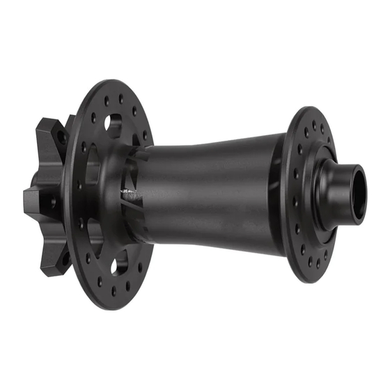
E x p l o d e d V i e w - F r o n t H u b End Cap Wave Spring Zipp 6903/61903 hub bearing Hub Shell Zipp 6903/61903 hub bearing Axle End Cap F r o n t H u b E n d C a p s... - Page 34 F r o n t H u b B e a r i n g R e m o v a l Insert the Park Tool AV-4 or AV-5 Axle and Spindle Vise Insert tool into a vise. Clamp the non-drive side end cap into the vise insert tool and pull up on the wheel/hub to remove the end cap.
- Page 35 Spray isopropyl alcohol onto the axle and clean it with a shop towel. NOTI CE To prevent damage to the hub surfaces, do not use acetone or similar products to clean parts. Isopropyl Alcohol Insert the 17 mm Bearing Puller slotted attachment through the drive side bearing.
-
Page 36: Front Hub Bearing Removal
Clean the hub shell with isopropyl alcohol and a shop towel. Isopropyl Alcohol Shop Towel Front Hub Bearing Removal... - Page 37 F r o n t H u b B e a r i n g I n s t a l l a t i o n Install a new Zipp 6903/61903 hub bearing into the drive side of the hub with the black seal facing outward.
- Page 38 Slide a 6903 30x17 tool onto the Press Tool threaded rod. Insert the threaded rod through the bearing on the non-drive side of the hub shell. Slide a second 6903 30x17 tool onto the threaded rod. Thread the Press Tool handle onto the threaded rod. Turn the handle clockwise to press the bearing into the hub until it is hand-tight.
-
Page 39: Front Hub Bearing Installation
Install the wave spring onto the non-drive side of the axle. You may need a tool to press the wave spring against the bearing face. NOTI CE Do not scratch the axle when using a tool to install the wave spring. The wave spring is crucial to hub performance and must be installed onto the axle. - Page 40 Vuka Bull™, Vuka Clip™, Vuka Fit™, Wide Angle™, WiFLi™, X1™, X3™, X4™, X5™, X7™, X9™, X-Actuation™, XC™, X-Dome™, XD™, XDR™, XG-1150™, XG-1175™, XG-1180™, XG-1190™, X-Glide™, X-GlideR™, X-Horizon™, XLoc Sprint™, XPLR™, XPRESSO™, XPRO™, X-Range™, XX™, Yari™, ZEB™, Zero Loss™, ZM2™, ZR1™ Specifications and colors subject to change without prior notice.
- Page 41 ASIAN HEADQUARTERS WORLD HEADQUARTERS EUROPEAN HEADQUARTERS SRAM Taiwan SRAM LLC SRAM Europe No. 1598-8 Chung Shan Road 1000 W. Fulton Market, 4th Floor Paasbosweg 14-16 Shen Kang Hsiang, Taichung City Chicago, Illinois 60607 3862ZS Nijkerk Taiwan R.O.C. U.S.A. The Netherlands...