Table of Contents
Advertisement
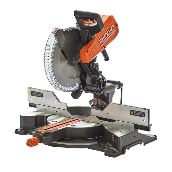
OPERATOR'S MANUAL
12 inch Max Reach Miter Saw
R4231
Your saw has been engineered and manufactured to our high standard for dependability, ease of operation, and operator
safety. When properly cared for, it will give you years of rugged, trouble-free performance.
WARNING:
To reduce the risk of injury, the user must read and understand the operator's manual before using this product.
SAVE THIS MANUAL FOR FUTURE REFERENCE
Advertisement
Table of Contents

Related Manuals for RIDGID R4231


Summary of Contents for RIDGID R4231
- Page 1 OPERATOR’S MANUAL 12 inch Max Reach Miter Saw R4231 Your saw has been engineered and manufactured to our high standard for dependability, ease of operation, and operator safety. When properly cared for, it will give you years of rugged, trouble-free performance.
-
Page 2: Table Of Contents
TABLE OF CONTENTS FEATURES MITER LOCK ADJUSTMENT .......... 18 ..............2 THROAT PLATE ............19 PRODUCT SPECIFICATIONS ........... 2 MOUNTING AND TRANSPORTATION KNOW YOUR COMPOUND MITER SAW ......5 ..... 20 IMPORTANT SAFETY INSTRUCTIONS PREPARATIONS FOR TRANSPORTATION ....... 20 ...... 6 MOUNTING SAW TO STABLE SURFACE ...... - Page 3 FEATURES Figure 1 On/Off Switch and Lockout Hole Work Table Safety Switch Work Clamp Dust Bag Blade Depth Stop Screw/Depth Stop Plate Lower Guard Bevel Scale and Indicator Spindle Lock Sliding Fence Upper Guard Base Back Fence Support Throat Plate T30 Torx/Blade Wrench...
- Page 4 FEATURES Figure 2 Motor End Cap Miter Lock Knob Carrying Handle Miter Detent Lock/Unlock Button Slide Lock Lever Mounting Holes (4) Saw Head Lock Pin Bevel Lock/Unlock Handle Miter Scale and Indicator Bevel Detent Latch Miter Detent Override Button Slide Resistance Adjustment...
-
Page 5: Know Your Compound Miter Saw
FEATURES KNOW YOUR COMPOUND MITER SAW On/Off Switch and Lockout Hole: This saw T30 Torx/Blade Wrench: This wrench should be used is activated by an easy to use, hand operated, when removing, installing, or changing the blade. power switch. When not in use the saw should be Motor End Cap: This provides access to your saw’s disconnected from the power supply and locked using a motor’s Brush Caps/carbon brushes, in the event they... -
Page 6: Important Safety Instructions
IMPORTANT SAFETY INSTRUCTIONS CAREFULLY READ AND FOLLOW ALL WARNINGS AND INSTRUCTIONS ON YOUR PRODUCT AND IN THIS MANUAL. SAVE THIS MANUAL. MAKE SURE ALL USERS ARE FAMILIAR WITH ITS WARNINGS AND INSTRUCTIONS WHEN USING THE TOOL. Improper operation, maintenance or modification of tools or equipment could result in serious injury and/or property damage. -
Page 7: General Power Tool Safety Warnings
GENERAL POWER TOOL SAFETY WARNINGS Read all safety warnings, instructions, illustrations and specifications provided with this power tool. Failure to follow all instructions listed below may result in electric shock, fire and/or serious injury. Save all warnings and instructions for future reference. The term “power tool”... -
Page 8: Safety Instructions For Miter Saws
GENERAL POWER TOOL SAFETY WARNINGS d. Store idle power tools out of the reach of children and do not allow persons unfamiliar with the power tool or these instructions to operate the power tool. Power tools are dangerous in the hands of untrained users. -
Page 9: Proposition 65 Warning
SAFETY INSTRUCTIONS FOR MITER SAWS l. Provide adequate support such as table extensions, saw horses, etc. for a workpiece that is wider or longer than the table top . Workpieces longer or wider than the miter saw table can tilt if not securely supported. If the cut-off piece or workpiece tips, it can lift the lower guard or be thrown by the spinning blade. -
Page 10: Power Connections
POWER CONNECTIONS not be less than #12 wire and should be protected with a This saw is equipped with a 15-amp motor for use with a 120- 20-amp time lag fuse and/or circuit breaker. If an extension volt, 60-HZ alternating current. cord is used, use ONLY 3-wire extension cords which have For voltage, the wiring in a shop is as important as the motor’s 3-prong grounding-type plugs and matching receptacle which... -
Page 11: Unpacking
Compare package contents to Component Parts List and Hardware Package List prior to assembly to make sure all items are present. Carefully inspect parts to make sure no damage occurred during shipping. If any parts are missing, damaged or pre- assembled, DO NOT assemble. Instead, call RIDGID Customer Service at (toll free) 1-888-359-4778. -
Page 12: Assembly
The Saw can tip over if the Saw Head is released suddenly and the Saw is not secured to a work surface. ALWAYS secure this Saw to a stable work surface before any use. If any parts are damaged or missing DO NOT operate this tool until the parts are replaced. Please call RIDGID •... -
Page 13: Work Clamp
ASSEMBLY WORK CLAMP See Figure 5 The vertical Work Clamp secures the workpiece to the table to provide more stability and keeps the workpiece from creeping toward the saw blade. To install the vertical Work Clamp do the following: Place the Clamp Shaft in either hole on the Miter Base. -
Page 14: Install/Remove/Replace The Blade
ASSEMBLY INSTALL/REMOVE BLADE required blade size A 12 inch Blade is the for the Saw. Larger blades will come into contact with the Blade Guards and smaller blades will not be adequately guarded. See Figures 8-10. Make sure the Saw is unplugged. Raise the Saw Arm to the full upright position. -
Page 15: Adjustments
ADJUSTMENTS ALIGN THE BLADE TO TABLE Your saw is calibrated at the factory to cut true. Over time the saw’s calibration may drift and will need to be re-calibrated. See Figure 11. Unplug the Saw Lower the saw head all the way down to the transport position and engage the saw head lock pin to hold it in place. -
Page 16: Align The Blade To Fence
ADJUSTMENTS ALIGN THE BLADE TO FENCE Your saw is calibrated at the factory to cut true. Over time the saw’s calibration may drift and will need to be re-calibrated. UNLOCK See Figure 12. Unplug the Saw. LOCK Lower the saw head all the way down to the transport position and engage the saw head lock pin to hold it in place. -
Page 17: Depth Stop Adjustment
ADJUSTMENTS DEPTH STOP ADJUSTMENT This miter saw is equipped with an adjustable depth stop for making non-through cuts. Refer to Figure 14 and follow these instructions in order to set the depth stop at a specific cut depth: Rotate the depth stop plate counterclockwise into the down position. -
Page 18: Slide Resistance
ADJUSTMENTS SLIDE RESISTANCE ADJUSTMENT See Figure 17. The slide resistance (friction) on your saw is adjustable. Use the supplied 4mm Hex wrench. Locate the friction adjustment screw on the saw slide . Turn right to LOOSEN TIGHTEN tighten the sliding friction. Turn left to loosen the sliding friction. -
Page 19: Throat Plate
Remove the six screws which hold the throat plate. Lift the throat plate off the work table. Replace the throat plate only using a RIDGID ® authorized service part. Tighten the six screws which hold the throat plate. -
Page 20: Mounting And Transportation
MOUNTING AND TRANSPORTATION Before moving/transporting your saw it is important to make sure all of the following steps have been followed to ensure a safe condition for transportation. Failure to do so can result in serious personal injury. ALWAYS turn the power off and unplug saw before transporting. •... -
Page 21: Mounting Saw To Stable Surface
MOUNTING AND TRANSPORTATION MOUNTING SAW TO STABLE SURFACE To ensure safe and accurate operation, this saw should be mounted to a stable and level surface such as a sturdy workbench. To mount the tool to a stable surface, refer to Figure 22 and do the following: Locate the four mounting holes in the base of the saw Secure the tool to the mounting surface using 3/8 inch diameter machine bolts, lock washers, and hex nuts... -
Page 22: Operation
OPERATION • DO NOT allow familiarity with tools to make you careless. Remember that a careless fraction of a second is sufficient to inflict serious personal injury. ALWAYS wear eye protection with side shields and marked to comply with ANSI Z87.1 Failure to do so could result in objects •... -
Page 23: Cutting Warped Material
OPERATION CUTTING WARPED MATERIAL See Figure 25. When attempting to cut warped material, the CONVEX face should be against the fence. See Figure 26. NEVER position a piece of warped material with the CONCAVE face or edge against the fence. It will pinch the blade near the completion of the cut. -
Page 24: Supporting Long Workpieces
OPERATION SUPPORTING LONG WORKPIECES Additional support may be used to make the workpiece lay flat on the saw table. Use the included work clamp or a C-clamp to secure the workpiece to the miter saw table. See Figure 28. Figure 28 POWER SWITCH LOCK To prevent any unauthorized person from operating this saw, a padlock (not included) should be installed... -
Page 25: Non-Sliding Cuts
OPERATION Before turning the saw power ON, check to make sure saw head and blade will not make contact with the provided work clamp or fence during the cutting operation. Position the work clamp and fence to avoid contact with the miter saw head. -
Page 26: For Bevel Cuts
OPERATION BEVEL CUTS To avoid serious personal injury, before turning the saw power ON, check to make sure saw head and blade will not make contact with the provided work clamp or fence during the cutting operation. Position the work clamp and fence to avoid contact with the miter saw head. -
Page 27: For Compound Miter Cuts
OPERATION COMPOUND MITER CUTS To avoid serious personal injury, before turning the saw power ON: Check to make sure saw head and blade will not make contact with the provided work clamp or fence during the cutting operation. Position the work clamp and fence to avoid contact with the miter saw head. -
Page 28: Slide Cuts
OPERATION SLIDE CUTS A slide cut should NEVER be performed by pulling the saw toward you. Due to the blade rotation direction, this can cause the saw blade to climb over the workpiece and towards the operator. Failure to follow this warning could result in serious personal injury. -
Page 29: Tips For Cutting Crown Molding
OPERATION TIPS FOR CUTTING CROWN MOLDING • The two edges of the molding that contact the ceiling and the wall are at angles that, when added together, equal exactly 90°. Most crown molding has a top rear angle (the section that fits flat against the ceiling) of 52° and a bottom rear angle (the section that fits flat against the wall) of 38°. -
Page 30: Auxiliary Fence
OPERATION AUXILIARY FENCE See Figure 37. For cutting certain workpieces, you may require a larger fence surface area to accommodate an auxiliary fence with a workpiece. The auxiliary fence should be made using 3/4 inch thick wood. Use the mounting holes (in bold) which are pre- drilled in the fence to attach an auxiliary fence. -
Page 31: Expand Worktable Area
OPERATION EXPAND WORKTABLE AREA This saw is designed to allow for large capacity cuts up to 2 x 12 inch. In order to make these cuts you will need to configure your saw appropriately. DO NOT use an auxiliary table board which will not fully support the workpiece during cutting operation. -
Page 32: Maintenance
MAINTENANCE To reduce the risk of injury, turn unit off and DO NOT at any time let brake fluids, disconnect it from power source before cleaning or servicing, gasoline, petroleum-based products, penetrating oils, etc., before installing and removing accessories, before adjusting come in contact with plastic parts. -
Page 33: Troubleshooting
® ® ® Service Centers. Please visit our Web Site www.ridgid.com for an on-line catalog or for the name or your nearest supplier. Since accessories other than those offered by RIDGID have not been tested with this product, use of ®... -
Page 34: Parts, Services Or Warranty Assistance
RIDGID Inc. All warranty communications failure or defect resulting from misuse, abuse, neglect, ® should be directed to Customer Service attn: RIDGID Stationary alteration, modification or repair by other than an authorized ® Power Tool Technical Service at (toll free) 1-888-359-4778. - Page 35 NOTES...
- Page 36 OPERATOR’S MANUAL 12 inch Max Reach Miter Saw R4231 Customer Service Information: For parts or service, do not return this product to the store. Contact your nearest RIDGID authorized service center. Be sure to provide all relevant information when ®...