Table of Contents
Advertisement
Quick Links
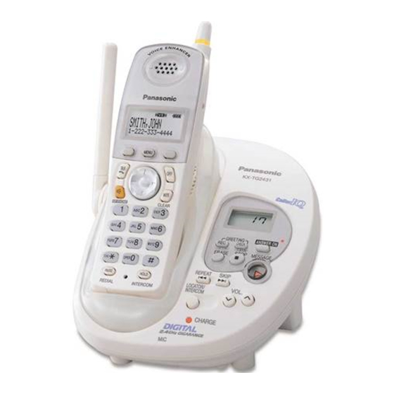
Telephone Equipment
KX-TG2431W
KX-TG2432W
KX-TG2432B
KX-TGA242W
KX-TGA242B
2.4GHz
Digital
System
White Version
Black Version
(for U.S.A.)
© 2005 Panasonic Communications Co., Ltd. All
rights
reserved.
distribution is a violation of law.
ORDER NO. KM40501580CE
Cordless
Answering
Unauthorized
copying
J01
and
Advertisement
Table of Contents

Related Manuals for Panasonic KX-TG2431W


Summary of Contents for Panasonic KX-TG2431W
- Page 1 ORDER NO. KM40501580CE Telephone Equipment KX-TG2431W KX-TG2432W KX-TG2432B KX-TGA242W KX-TGA242B 2.4GHz Digital Cordless Answering System White Version Black Version (for U.S.A.) © 2005 Panasonic Communications Co., Ltd. All rights reserved. Unauthorized copying distribution is a violation of law.
-
Page 2: Table Of Contents
KX-TG2431W / KX-TG2432W / KX-TG2432B / KX-TGA242W / KX-TGA242B Note: Because CONTENTS 3 to 6 are the extracts from the Operating Instructions of this model, they are subject to change without notice. Please refer to the original Operating Instructions for further information. -
Page 3: For Service Technicians
KX-TG2431W / KX-TG2432W / KX-TG2432B / KX-TGA242W / KX-TGA242B 1 FOR SERVICE TECHNICIANS ICs and LSIs are vulnerable to static electricity. When repairing, the following precautions will help prevent recurring malfunctions. 1. Cover plastic parts boxes with aluminum foil. 2. Ground the soldering irons. -
Page 4: Battery
KX-TG2431W / KX-TG2432W / KX-TG2432B / KX-TGA242W / KX-TGA242B 3 BATTERY 3.1. Battery Installation 3.2. Battery Charge 3.3. Recharging the Battery Note for service: The battery strength may not be indicated correctly if the battery is disconnected and connected again, even after it is fully... -
Page 5: Battery Strength
KX-TG2431W / KX-TG2432W / KX-TG2432B / KX-TGA242W / KX-TGA242B 3.4. Battery Strength 3.5. Battery Replacement 3.6. Battery Performance... -
Page 6: Settings
KX-TG2431W / KX-TG2432W / KX-TG2432B / KX-TGA242W / KX-TGA242B 4 SETTINGS 4.1. Connections... -
Page 7: Connecting An Optional Headset
KX-TG2431W / KX-TG2432W / KX-TG2432B / KX-TGA242W / KX-TGA242B 4.2. Connecting an Optional Headset... -
Page 8: Answering System
KX-TG2431W / KX-TG2432W / KX-TG2432B / KX-TGA242W / KX-TGA242B 5 ANSWERING SYSTEM The unit contains an answering system which can answer and record calls for you when you are unavailable to answer the phone. Important: • • • • Only 1 person can access the answering system (listen to messages, record a greeting message, etc.) at a time. -
Page 9: Turning The Answering System On/Off
KX-TG2431W / KX-TG2432W / KX-TG2432B / KX-TGA242W / KX-TGA242B 5.2. Turning the Answering System On/Off 5.3. Caller’s Recording Time 5.4. Message Alert... -
Page 10: Listening To Messages
KX-TG2431W / KX-TG2432W / KX-TG2432B / KX-TGA242W / KX-TGA242B 5.5. Listening to Messages 5.5.1. Listening to messages using the base unit... -
Page 11: Remote Operation
KX-TG2431W / KX-TG2432W / KX-TG2432B / KX-TGA242W / KX-TGA242B 5.5.2. Listening to messages using the handset 5.5.3. Answering system commands 5.6. Remote Operation... - Page 12 KX-TG2431W / KX-TG2432W / KX-TG2432B / KX-TGA242W / KX-TGA242B 5.6.1. Using the answering system remotely 5.6.2. Remote Code...
- Page 13 KX-TG2431W / KX-TG2432W / KX-TG2432B / KX-TGA242W / KX-TGA242B 5.6.3. Remote commands 5.6.4. Turning on the answering system remotely...
-
Page 14: Troubleshooting
KX-TG2431W / KX-TG2432W / KX-TG2432B / KX-TGA242W / KX-TGA242B 6 TROUBLESHOOTING 6.1. General Use Cross Reference: (*1) Battery Installation (P.4) (*2) Connections (P.6) (*3) Battery Charge (P.4) 6.2. Programmable Settings... -
Page 15: Making/Answering Calls, Intercom
KX-TG2431W / KX-TG2432W / KX-TG2432B / KX-TGA242W / KX-TGA242B 6.3. Making/Answering Calls, Intercom Cross Reference: (*4) Connecting an Optional Headset (P.7) 6.4. Phonebook... -
Page 16: Caller Id
KX-TG2431W / KX-TG2432W / KX-TG2432B / KX-TGA242W / KX-TGA242B 6.5. Caller ID... -
Page 17: Answering System
KX-TG2431W / KX-TG2432W / KX-TG2432B / KX-TGA242W / KX-TGA242B 6.6. Answering System Cross Reference: (*5) Remote Code (P.12) (*6) Turning the Answering System On/Off (P.9) (*7) Caller’s Recording Time (P.9) (*8) Listening to messages using the base unit (P.10) (*9) Message Alert (P.9) -
Page 18: Battery Charge
KX-TG2431W / KX-TG2432W / KX-TG2432B / KX-TGA242W / KX-TGA242B 6.7. Battery Charge Cross Reference: (*10) Battery Charge (P.4) (*11) Battery Replacement (P.5) 6.8. Power Failure Cross Reference: (*12) Connections (P.6) -
Page 19: Replacement Parts List
KX-TG2431W / KX-TG2432W / KX-TG2432B / KX-TGA242W / KX-TGA242B 7 REPLACEMENT PARTS LIST Note: 1. Important safety notice Components identified by the mark indicates special characteristics important for safety. When replacing any of these components, only use specified manufacture´s parts. -
Page 20: For Schematic Diagram
KX-TG2431W / KX-TG2432W / KX-TG2432B / KX-TGA242W / KX-TGA242B 8 FOR SCHEMATIC DIAGRAM 8.1. Base Unit (SCHEMATIC DIAGRAM (BASE UNIT_MAIN)) 8.1.1. Acoustic Testing Mode Notes: 1. DC voltage measurements are taken with voltmeter from the negative voltage line. 2. This schematic diagram may be modified at any time with the development of new technology. - Page 21 KX-TG2431W / KX-TG2432W / KX-TG2432B / KX-TGA242W / KX-TGA242B Memo...
- Page 22 KX-TG2431W / KX-TG2432W / KX-TG2432B / KX-TGA242W / KX-TGA242B 9 SCHEMATIC DIAGRAM (BASE UNIT_MAIN) VBATT2 VBATT2 MOD_EN MOD_EN 2.5V SDIO SDIO IC301 SDATA SDATA 2.5V SCLK SCLK R523 39K C521 C3P R521 1.8K Q521 TX_DATA TX_DATA RX_GAIN RX_GAIN RX_EN RX_EN...
- Page 23 KX-TG2431W / KX-TG2432W / KX-TG2432B / KX-TGA242W / KX-TGA242B REFERENCE 1XX : TEL LINE 3.3V 3XX : POWER, CHARGE, 4XX : RESET,MIC, SP 5XX : DSP,RF I/F IC331 6XX : FLASH, KEY, LCD L300 3.3u VCC 3.3V 3.3V 7XX : RF(2.4G) IC332 8XX : RF(5.8G)
- Page 24 10 SCHEMATIC DIAGRAM (BASE UNIT_RF PART) MOD_EN 2.5V L902 VBATT2 10nH (PF) SDIO SDATA SCLK L905 R919 TX_DATA 10nH C983 K1000P C990 K1000P R930 C984 RX_GAIN J100P C991 2.4GHz TX 2.4GHz RF C938 VCC_PLL2A R940 D10P VCC_PLL2B GND_TX R931 C918 L911 RX_EN FL901...
- Page 25 11 SCHEMATIC DIAGRAM (BASE UNIT_OPERATION) 2AP_VCC LED901 MSG_LED LED903 CHG_LED LED904 ANS_LED KEYS_A KEYS_B KEYS_C KEYS_D COM1 COM2 SEG3 SEG4 SEG5 SEG6 SEG7 SEG8 SEG9 SEG10 SEG11 SEG12 KEYIN3 KEYIN2 25 KEYIN1 DOWN CN901 SKIP ERASE STOP KX-TG2431/2432 SCHEMATIC DIAGRAM (Base Unit_Operation)
- Page 26 KX-TG2431W / KX-TG2432W / KX-TG2432B / KX-TGA242W / KX-TGA242B 12 SCHEMATIC DIAGRAM (HANDSET_MAIN) to RF PART C246 K0.1 OSC_IN RSSI TX_DATA MOD_EN RX_EN TX_EN RX_GAIN RX_DATA SHCTRL RF_RESET (10) IC249 (11) SDATA (12) SCLK SDIO RESET R249 VBATT2 (13) FLASH_BOOT...
- Page 27 KX-TG2431W / KX-TG2432W / KX-TG2432B / KX-TGA242W / KX-TGA242B TEST SIGNAL FREQUENCY:1KHz 8bit-MPU Headset TX Additional small PCB -37dBm/600 C340 R340 K0.01 50mVp-p R331 2.6V HEADSET_JACK L331 L332 Q331 MIC1 MIC2 R332 R225 L334 Headset RX CN331 HEADSET-DET X201 170mVp-p/150 (Vol.
- Page 28 13 SCHEMATIC DIAGRAM (HANDSET_RF PART) MOD_EN 2.5V L902 VBATT2 10nH (PF) SDIO SDATA SCLK L905 R919 TX_DATA 10nH C983 K1000P C990 K1000P R930 C984 RX_GAIN J100P C991 2.4GHz TX 2.4GHz RF C938 VCC_PLL2A R940 D10P VCC_PLL2B GND_TX R931 C918 L911 RX_EN FL901 GND_RX...
-
Page 29: Schematic Diagram (Charger Unit)
14 SCHEMATIC DIAGRAM (CHARGER UNIT) DC JACK L1 4.7 Vout R7 0 R8 1.0K 1u50V 1u50V LED1 CHARGE PAD CHARGE+ CHARGE- R3 100 SCHEMATIC DIAGRAM (Charger Unit) - Page 30 KX-TG2431W / KX-TG2432W / KX-TG2432B / KX-TGA242W / KX-TGA242B H.M./N KXTG2431W-AK KXTG2432W-AK KXTG2432B-AK KXTGA242W-AK KXTGA242B-AK...