
Related Manuals for Canon PD-704


Summary of Contents for Canon PD-704
- Page 1 Non-Contact Displacement Sensor PD-704 User’s Manual Rev 1.00 Please read this manual carefully before operation. Please keep it in a safe place for future reference. Non-Contact Displacement Sensor User’s Manual Rev 1.00...
- Page 2 Introduction This manual provides the information on the hardware of the Non-Contact Displacement Sensor and the basic operating procedures. To make full use of the performance and functions of the Non-Contact Displacement Sensor, please read this manual carefully and understand fully before operation. Furthermore, please keep this manual in a safe place for future reference.
- Page 3 Cautions on Length Measurement CAUTION After powering on, wait for 30 minutes before use. Failure to observe this caution may cause drift for length measurement values. Dusts, water, oil, etc. on the window part of the equipment may cause a length measurement error. Wipe off deposits with clean air.
- Page 4 Japan VCCI この装置は、クラスA情報技術装置です。 この装置を家庭環境で使用すると電波妨害を引き起こすことがあります。 この場合には使用者が適切な対策を講ずるよう要求されることがあります。 VCCI-A This is a class A product. In a domestic environment this product may cause radio interference in which case the user may be required to take adequate measures. Korea A 급 기기 (업무용 정보통신기기) 이...
-
Page 5: Table Of Contents
— Contents — 1. Before Use ....................6 1-1. System Configuration ......................6 1-2. Accessories ........................7 1-3. Names and Functions of Parts ....................7 1-4. Installation/Connection......................9 1-4-1. Fixing the main unit ......................9 1-4-2. Checking the target measurement object ................9 1-4-3. -
Page 6: Before Use
1. Before Use This chapter explains the configuration of the Non-Contact Displacement Sensor, precautions, and preparation required before use. Please read this chapter before operation. 1-1. System Configuration The equipment can be used with commercially available devices for various purposes. Standard Configuration Main unit USB cable... -
Page 7: Accessories
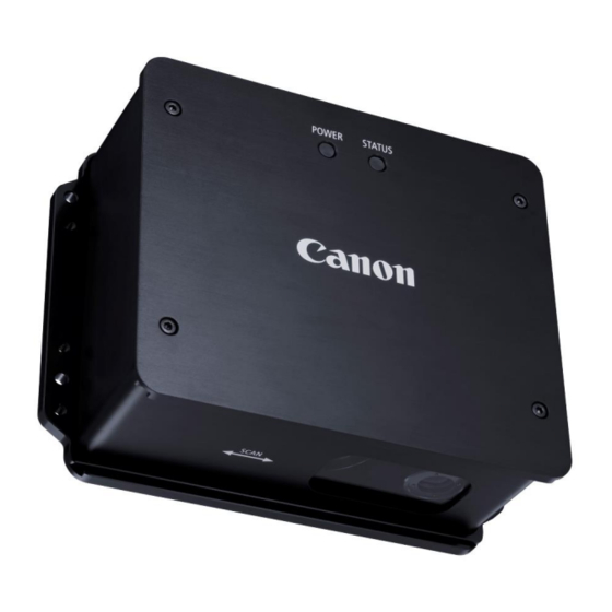
1-2. Accessories The following shows the standard configuration. Before use, please confirm that all the following items are included. Main unit Power cable Non-Contact Displacement Sensor software User’s manual For optional items, see section 4-3. 1-3. Names and Functions of Parts Main unit Main unit ①... - Page 8 ③ Power connector Connect the power cable (AM4-0085). 12 to 24V DC power input is supported. ④ Status indicator Turns on or blinks while the main unit is operating. Condition Power Status Powered on A warning occurs Blinking An error occurs ⑤...
-
Page 9: Installation/Connection
1-4. Installation/Connection 1-4-1. Fixing the main unit Mount the main unit with M4 screws. The board thickness of the M4 fixing parts is 6 mm. For the screw fixing parts, see the following dimensions. Secure a sufficient engagement allowance (5 or more pitches recommended) to fix screws and bolts/nuts. Positioning pins that match the sides of the main unit make it easier to mount the main unit. - Page 10 When an obstacle is placed between the equipment and the target measurement object, you may not measure. Do not locate an obstacle at the hatched part. Non-Contact Displacement Sensor User’s Manual Rev 1.00...
-
Page 11: Connecting
1-4-3. Connecting - Connecting to a computer Connect the USB cable and power cable. When the DC power is turned on, the main unit is turned on. For details, see chapter “3. I/O Terminals.” - Connecting to an external device (such as a programmable controller) Connect the optional I/O cable and power cable. -
Page 12: Measuring The Length And Setting The Functions
2. Measuring the Length and Setting the Functions 2-1. Obtaining the Length Measurement Values Before starting to measure the length, turn on the power and confirm that power indicator of the main unit is lit on. 2-1-1. Using the application to obtain the length measurement values Connect the main unit to a computer, and use the Non-Contact Displacement Sensor software to measure the length. -
Page 13: Setting The Length Measurement Parameters
2-2. Setting the Length Measurement Parameters Use the “Non-Contact Displacement Sensor Software” to set the length measurement parameters. For details, see the User’s Manual of Non-Contact Displacement Sensor Software. 2-2-1. Setting the pulse resolution The main unit outputs AB phase pulse signals as the length measurement information. The resolution of AB phase pulse can be set. -
Page 14: Calibration
2-3. Calibration An absolute length measurement value error may occur depending on the installation state of the main unit or the characteristics of the target measurement object. Calibration allows you to obtain a length measurement value close to your estimate. What are required for calibration - A sample equivalent to the actual length measurement object - A measure to move by already known length... -
Page 15: I/O Terminals
3. I/O Terminals 3-1. Function of I/O Terminals This section explains the function of I/O terminals. 3-1-1. Power cable terminals Connect the power cable terminals to the 12 to 24V DC power supplies (Power capacity: 20W or more). The terminals are ring-shaped for M4. The following figure shows an example to connect the terminals to 12V DC switching power supplies. -
Page 16: Specifications
4. Specifications 4-1. Main Specifications Measurement distance 70mm (WD:Working Distance) Measurement range ±15mm -4,000mm/s to 4,000mm/s Measutement speed range (Including the stop state) Maximum acceleration 100G of target measurement object Measurement resolution 1μm Measurement WD:70mm±5mm ±0.2% or 100μm accuracy ※1 WD:70mm±15mm ±0.5% or 100μm Measurement repeatability ※2 0.02% or 20μm... -
Page 17: External Dimensions
4-2. External Dimensions Center of light reception Non-Contact Displacement Sensor User’s Manual Rev 1.00... -
Page 18: Options
4-3. Options 4-3-1. I/O cable kit I/O cable Waterproof USB connector cap 4-3-2. USB cable kit USB cable Waterproof I/O connector cap 4-3-3. Protective cover unit This unit protects the optical window of the main unit from dirt or shock. If the optical window is expected to get dirty, e.g., in a location where oil splashes, it is recommended that you attach the protective cover unit. -
Page 19: Measurement Distance Adjustment Tool
4-3-4. Measurement distance adjustment tool This tool allows you to visually find the best measurement distance. - How to use the measurement distance adjustment tool Insert the measurement distance adjustment tool to the main unit, and then secure it with the bundled M4 (L = 6) screws. -
Page 20: Characteristics
4-4. Characteristics 4-4-1. Spot size and light receiving area The spot size of light beam is about Φ30 mm. The light receiving area is 4.8 X 0.2 mm with a central focus on the optical axis of a light receiving optical system. Main unit Light receiving area Light beam... -
Page 21: Guarantee And Service
Product serial number (labeled on the product) unknown Fault attributable to other equipment connected Canon will take no responsibility for direct or indirect damage caused by a fault or use of this product or incidental damage (e.g. loss of profit by the use of this product). -
Page 22: Appendix
6. Appendix 6-1. Troubleshooting Symptom Check Action The status Is the power turned on? Turn on the power. indicator does not Is the power cable correctly Connect the power cable correctly. turn on. connected? The error indicator Use the Non-Contact Displacement Sensor -... -
Page 23: Error
set in detail (e.g., 1 um), the output pulse frequency may become high and exceed the response frequency of the counter. Set the appropriate pulse resolution depending on the response frequency of the counter in use and the expected speed of the target measurement object. -
Page 24: I/O Circuit
6-4. I/O Circuit The following shows the input and output circuits. ■ Output circuit Equivalent to AM26LV31E Phase A pulse, Phase B pulse Internal circuit Photocoupler * ERROR_G and WARNING_G are separated. * If an error or a warning occurs, a photocoupler of each terminals turns off. ■... -
Page 25: Target Measurement Object
6-5. Target Measurement Object The equipment optically obtains minute patterns on the surface of the target measurement object to measure the length. If the surface of the target measurement object is similar to a mirror, the minute patterns may be difficult to be distinguished and the length may not be measured. - Page 26 Sales/Service Contact CANON MARKETING JAPAN INC. 5F Canon Konan Building, 2--13--29, Konan, Minato-ku, Tokyo, 108--8011, Japan Sales Section 1 Production Innovation Equipment Sales Department Industrial Equipment Business Unit Phone : +81-3-3740-3336, Fax :+81-3-3740-3356 CANON INC. 30-2, Shimomaruko 3-chome, Ohta-ku, TOKYO, 146-8501, Japan •...