Advertisement
Quick Links
SHARP SERVICE MANUAL
PARTS IDENTIFICATIONS AND SPECIFIC INFORMATION ................................................
CAUTIONS FOR USE ............................................................................................................
CLEANING AND MAINTENANCE ..........................................................................................
WIRING DIAGRAM AND CIRCUIT DIAGRAM .......................................................................
COMPONENT REPLACEMENT PROCEDURE .....................................................................
TROUBLESHOOTING ............................................................................................................
SERVICE PARTS LIST ...........................................................................................................
In the interests of user-safety (Required by safety
regulations in some countries) the set should be restore
to its original condition and only parts identical to those
specified should be used.
TABLE OF CONTENTS
SHARP CORPORATION
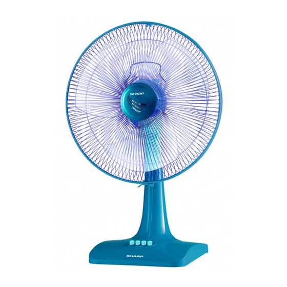
ELECTRIC FAN
MODEL
PJ-TA161
Page
2
3
3
4
5 - 6
7
8-10
Advertisement

Related Manuals for Sharp PJ-TA161


Summary of Contents for Sharp PJ-TA161
-
Page 1: Table Of Contents
SHARP SERVICE MANUAL ELECTRIC FAN MODEL PJ-TA161 In the interests of user-safety (Required by safety regulations in some countries) the set should be restore to its original condition and only parts identical to those specified should be used. TABLE OF CONTENTS Page PARTS IDENTIFICATIONS AND SPECIFIC INFORMATION .......... -
Page 2: Parts Identifications And Specific Information
Motor bracket Body Knob switch Rear grille Grille lock nut Blade Spinner fan Front grille Fixing lock SPECIFIC INFORMATION PJ-TA161 Model Rated voltage (V) Rated frequency (Hz) Power consumption (W) Blade (mm) Rated current (A) 0.21 Insulation class Temperature control 0.70... -
Page 3: Cautions For Use
CAUTIONS FOR USE 1. Do not disassemble or repair the electric fan by yourself, it may cause troubles such as a fire of electric shock. Consult your nearest dealer. 2. Incase the power cord is broken, it must be replaced by manufacturer or appointed service providers or equivalent professionals to avoid any damages. -
Page 4: Wiring Diagram And Circuit Diagram
WIRING DIAGRAM MOTOR ASS’Y GEAR BOX CIRCUIT DIAGRAM... -
Page 5: Component Replacement Procedure
COMPONENT REPLACEMENT PROCEDURE REMOVE OF GRILLE ASS’Y 1. Unlock the fixing lock and pull the front grille. 2. Turn the spinner fan clockwise and remove the blade. 3. Turn the grille lock nut counterclockwise and remove the rear grille. Motor ass’y Blade Spinner fan Front grille... - Page 6 REMOVE OF PIANO SWITCH ASS’Y 1. Remove the hard board. 2. Cut 4 lead wires from the piano switch ass’y. 3. Remove 2 screws holding to the piano switch ass’y. 4. Remove the piano switch ass’y from the body, detach the knob switch, spring and remove the insulation sheet from piano switch ass’y.
-
Page 7: Troubleshooting
TROUBLESHOOTING Problem Possible Cause Corrective Action 1. Motor does not operate. 1. Connector of power supply cord. Fan does not operate. 2. Repair. 2. Faulty connect the power connector or switch. 3. Coil stator shock or lack of. 3. Replace motor or stator parts 4. -
Page 8: Service Parts List
SERVICE PARTS LIST PARTS CODE REF. NO DESCRIPTION Q’TY PRICE (FEC) PRINTING & PACKAGING MATERIAL 10A102 INSTRUCTION BOOK 10A101 CARTON BOX 10A103 NAME PLATE 10A107 UPPER PAD 10A108A TA PARTITION - A for BASE 10A108B TA PARTITION - B for BLADE 10A108C TA PARTITION - C for GRILLE MECHANICAL PARTS... - Page 9 PARTS CODE REF. NO DESCRIPTION Q’TY PRICE (FEC) MECHANICAL PARTS 10A211LBE CLUTCH KNOB Beige 10A211DDG CLUTCH KNOB Dark Grey 10A211DLG CLUTCH KNOB Leaf Green 10A211LRD CLUTCH KNOB 10A211DTQ CLUTCH KNOB Turquoise 10A211DWH CLUTCH KNOB White 2-10 10A213ASY TURNING AXLE ASS’Y 2-11 10A212BEASY HINGE ASS’Y...