
Related Manuals for Honeywell 9410 Series


Summary of Contents for Honeywell 9410 Series
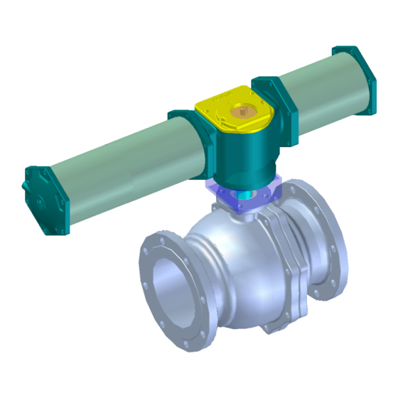
- Page 1 INSTALLATION, OPERATION, MAINTENANCE MANUAL Series 9410 Ball Valve 70-16-45-06-EN Revision: 1.1...
-
Page 2: Table Of Contents
Contents 1. General ....................... 1 1.1 Introduction to Valves ......................1 2. Storage ....................... 1 3. Installation ....................2 4. Operation ....................7 4.1 Inspections before Operation ..................... 7 5. Maintenance and Repair ................8 5.1 General .......................... -
Page 3: General
A) The ball valve has been designed for the requirements and applications of piping. B) The most important feature of the Honeywell angle valve is its body that has been manufactured in appropriate sizes to meet the requirements of piping. It consists of a body that includes a cage to control flow speed, a seat ring, a bonnet, and an actuator. -
Page 4: Installation
3. Installation Like any other valves, the Honeywell control valve must be installed carefully at first according to the following cautions to use it for many years without malfunction. - Page 5 E) When assembling the valve, you should use a specified gasket, and install it in parallel with the other flange. Also, you are recommended to fasten the bolts in several parts in a balanced manner sequentially in diagonal direction. (See Fig 3.1) Fig 3.1 Procedure for Fastening Flange Bolts F) Install the valve at right angle to the ground as much as possible.
- Page 6 G) A minimum space is required for maintenance of the valve installation area. (See Fig 3.4) In addition, a space for manual operation is required if a manual hand wheel has been installed. Fig 3.4 Space required for control valve installation ☞...
- Page 7 Therefore, use a control valve that has the feature to control flow by opening the bypass valve. Moreover, it is ideal to choose the same flow characteristics and size as those of control valve. Fig 3.6 shows an example of ideal control valve installation recommended by Honeywell. Main steam line Fig 3.6 Example of Control...
- Page 8 ♣ NOTE To maintain a constant pressure at the entrance for all tracks of the valve, the straight pipe length at the valve entrance must be at least 10 to 20 times the pipe diameter. For the fluid to maintain the specified pressure after passing the valve and to prevent noise or vibration by turbulent flow, the straight pipe length at the valve exit must be at least 3 to 5 times the pipe diameter.
-
Page 9: Operation
4. Operation 4.1 Inspections before Operation ① Check whether there is any leak from all connections including the air pipe connections. ② To check whether there is any leak from gland packing and gaskets, apply a pressure to the pipeline. If any leak is detected, remove pressure from the pipeline and fasten the gland flange nut. -
Page 10: Maintenance And Repair
5. Maintenance and Repair REGULAR INSPECTION Repair and inspect as described below. If any malfunction occurs, take appropriate measures according to the preventive maintenance procedures and troubleshooting in Chapter 6. Also, disassemble and inspect the valve body and actuator during the regular overhaul period, and replace parts if necessary. ♣... -
Page 11: General
5.1 General - WARNING - To prevent human injuries and damages to control system, close the block valve, remove instrument air and signals from the valve and open the bypass valve to switch over the pressure from the line to the bypass. Then slowly unfasten the bolts from the pipe until the internal pressure of the body is completely released and remove the valve before disassembling the actuator. -
Page 12: Assembly
INSPECTION AFTER DISASSEMBLY ① Are there any damages to the seat ring and ball? ② Are there any damages to the gasket and gland packing? ♣ RECOMMENDATIONS ① Be sure to inspect and replace worn out parts before reassembling them. ②... -
Page 13: Preventive Maintenance And Troubleshooting
6. Preventive Maintenance and Troubleshooting ♣ NOTE Replace parts after inspection by referring to the Part Replacement Cycle Sheet in Section 5. For other parts, replace them to prevent damages to other devices when they show a wearing sign. 6.1 Troubleshooting Table 6.1 shows some remedies to general problems that may occur at the site while using ball valves. -
Page 14: Others
Problem Solution 1. Check the air pressure supplied to the valve and then check the condition of the filter regulator. 2. Check the operations of parts such as solenoid valve and air operated valve. Ball does not move. 3. Disassemble the valve and check whether there are any foreign substances in the ball and seat. - Page 15 China – PRC - Shanghai Honeywell China Inc. Phone: (86-21) 5257-4568 Fax: (86-21) 6237-2826 Singapore Honeywell Pte Ltd. Phone: +(65) 6580 3278 Fax: +(65) 6445-3033 South Korea Honeywell Korea Co., Ltd. Phone: +(822) 799 6114 Fax: +(822) 792 9015 - 13 -...
- Page 16 For more information To learn more about Honeywell Control valves, Visit www.honeywellprocess.com Or contact your Honeywell Account Manager Process Solutions Honeywell 1250 W Sam Houston Pkwy S Houston, TX 77042 Honeywell Control Systems Ltd Honeywell Honeywell House, Skimped Hill Lane...