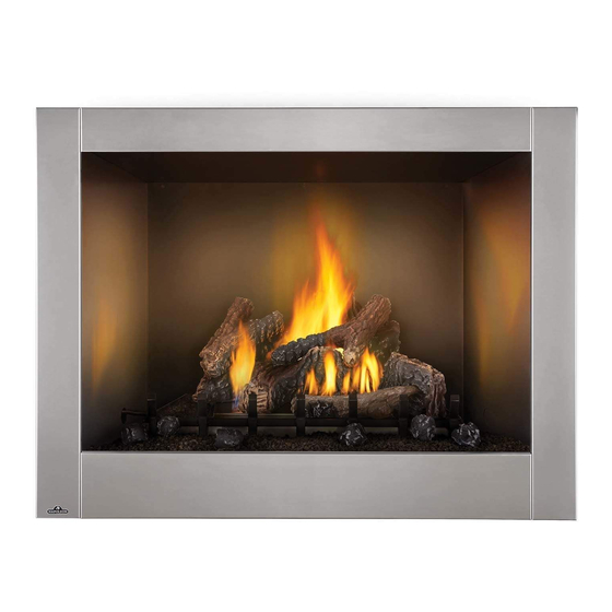
Napoleon Riverside GSS42CFN Installation And Operation Manual
Clean face
Hide thumbs
Also See for Riverside GSS42CFN:
Table of Contents
Advertisement
Available languages
Available languages
Quick Links
SAFETY INFORMATION
WARNING
!
If the information in these instructions are not
followed exactly, a fi re or explosion may result
causing property damage, personal injury or
loss of life. Read the installation, operating and
maintenance instructions thoroughly before
installing or servicing this equipment.
- Do not store or use gasoline or other
fl ammable vapors and liquids in the vicinity of this
or any other appliance.
- An LP-cylinder not connected for use shall not be
stored in the vicinity of this or any other appliance.
WHAT TO DO IF YOU SMELL GAS:
• Do not try to light any appliance.
• Shut off gas to the appliance.
• Extinguish any open fl ame.
• If odour continues, leave the area immediately.
• Do not touch any electrical switch; do not use
any phone in your building.
• Immediately call your gas supplier from a neigh-
bour's phone. Follow the gas supplier's instruc-
tions.
• If you cannot reach your gas supplier, call the fi re
department.
Failure to follow these instructions could result in
fi re or explosion, which could cause property dam-
age, personal injury, or death.
- Installation and service must be performed
by a qualifi ed installer, service agency, or the
gas supplier.
This appliance is only for use with the type of gas
indicated on the rating plate. This appliance is
not convertible for use with other gases, unless a
certifi ed kit is used.
INSTALLER:
Leave this manual with the appliance
CONSUMER:
Retain this manual for future reference
Wolf Steel Ltd., 24 Napoleon Rd., Barrie, ON, L4M 0G8 Canada / 103 Miller Drive, Crittenden, Kentucky, USA, 41030
$10.00
Phone 1 (866) 820-8686 • www.napoleon.com • hearth@napoleon.com
CERTIFIED TO THE CANADIAN AND AMERICAN NATIONAL STANDARDS:
CSA 2.22 AND ANSI Z21.50 FOR VENTED DECORATIVE GAS APPLIANCES
ENGLISH
FRENCH PG. 31
W415-2975 / 09.02.21
Advertisement
Chapters
Table of Contents

Related Manuals for Napoleon Riverside GSS42CFN


Summary of Contents for Napoleon Riverside GSS42CFN
- Page 1 CSA 2.22 AND ANSI Z21.50 FOR VENTED DECORATIVE GAS APPLIANCES CONSUMER: Retain this manual for future reference Wolf Steel Ltd., 24 Napoleon Rd., Barrie, ON, L4M 0G8 Canada / 103 Miller Drive, Crittenden, Kentucky, USA, 41030 Phone 1 (866) 820-8686 • www.napoleon.com • hearth@napoleon.com $10.00...
- Page 2 safety information W415-2975 / 09.02.21...
- Page 3 safety information • This appliance is hot when operated and can cause severe burns if contacted. • Any changes or alterations to this appliance or its controls can be dangerous and is prohibited. • Do not operate appliance before reading and understanding operating instructions.
- Page 4 safety information • Do not use a blower insert, heat exchanger insert or other accessory not approved for use with this appliance. • This appliance must not be connected to a chimney fl ue pipe serving a separate solid fuel burning appliance.
-
Page 5: Table Of Contents
table of contents general information combustion and ventilation air rates and effi ciencies general instructions rating plate information dimensions location framing gas inlet locations minimum framing dimensions minimum enclosure clearances minimum clearance to combustible enclosures electrical information optional wall switch installation gas installation operation nailing tabs... -
Page 6: General Information
general information Installer, please fi ll out the following information: Customer: ____________________________________________________________________ Address: ____________________________________________________________________ Date of Installation: ____________________________________________________________________ Location of Appliance: ____________________________________________________________________ Installer: ____________________________________________________________________ Dealer/Distributor Contact Number : ____________________________________________________________________ Serial #: ____________________________________________________________________ Model: Natural Gas: GSS42CFN Propane: GSS42CFP 1.0 general information When the appliance is installed at elevations above 4,500ft (1370m), and in the absence of specifi... -
Page 7: Rates And Effi Ciencies
general information rates and effi ciencies For your satisfaction, this appliance has been test-fi red to assure its operation and quality! RATES AND EFFICIENCIES Altitude (FT) 0-4,500 Max. Input (BTU/HR) 65,000 Min. Inlet Gas Supply Pressure 4.5" (11mb) w.c. 11" (27mb) w.c. Max. -
Page 8: Rating Plate Information
general information rating plate information This illustration is for reference only. Refer to the rating plate on the appliance for accurate information. note: The rating plate must remain with the appliance at all times. It must not be removed. dimensions W415-2975 / 09.02.21... -
Page 9: Location
2.0 location It is important when selecting a location for your appliance to ensure clearances to adjacent combustibles are met. This appliance is intended for installation on an outdoor patio or in your yard. It is highly recommended that this appliance be installed in a sheltered area (following the guidelines outlined below). Direct wind will cause an erratic fl... -
Page 10: Framing
3.0 framing note: When using optional fi nishing accessories, the framing dimensions and fi nishing materials may differ from what is outlined in the section below; refer to the leafl et instructions supplied in the accessory kit for specifi c framing and fi... -
Page 11: Minimum Framing Dimensions
framing minimum framing dimensions Minimum Clearance to Combustibles construction from appliance and vent surfaces: Framing 0” (0mm) to stand-offs (rear and sides only) Use a steel header for the top and two steel studs on the sides. Finishing 1” (25mm) to back and sides Non-combustible fi... -
Page 12: Minimum Enclosure Clearances
framing minimum enclosure clearances This appliance requires a minimum enclosure height of 58 1/2” (148.6cm). For temperature requirements, the enclosure space around and above the appliance must be left unobstructed. W415-2975 / 09.02.21... -
Page 13: Minimum Clearance To Combustible Enclosures
framing minimum clearance to combustible enclosures • Use only non-combustible material such as cement board, ceramic tiles, marble, etc. when fi nishing to the appliance. Do not use wood or drywall. * From top of appliance. ** An outdoor sealant must be used along the edge of the appliance and the non-combustible material to keep water from entering the chase. -
Page 14: Electrical Information
4.0 electrical information optional wall switch installation • Do not connect either the wall switch, thermostat or gas valve directly to 110 volt electricity. For ease of accessibility, an optional remote wall switch or millivolt thermostat may be installed in a convenient location. -
Page 15: Operation
6.0 operation • If you do not follow these instructions exactly, a fi re or explosion may result causing property damage, personal injury, or loss of life. • If applicable, always light the pilot whether for the fi rst time or if the gas supply has run out with the glass door opened or removed. -
Page 16: Nailing Tabs
7.0 nailing tabs To install the appliance face fl ush with the fi nished surface, position the framework to accommodate the thickness of the fi nished surface. Bend out the six nailing tabs, attached on top and on either side of the appliance and secure to the 2x4 framing. -
Page 17: Finishing
The logs are fragile and should be handled with care. PHAZER logs and glowing embers exclusive to Napoleon, provide a unique and realistic glowing effect that is different in every installation. Take the time to carefully position the glowing embers for a maximum glowing effect. -
Page 18: Glowing Embers (Optional)
fi nishing Position the slot in the bottom of the right log Position log F (W135-0481) in front of the front (W135-0670) onto the bracket beside the row of burner ports, and allow it to rest against burner on the right, with the charred face of the the backside of the grate assembly. -
Page 19: Logo Placement
fi nishing logo placement Remove the backing of the logo supplied. Centre the logo on the front of the appliance, ½” (12.7mm) in from the left side, as shown. minimum mantel clearances • Risk of fi re. Maintain specifi ed air space clearances to combustibles. Failure to comply with these instructions may cause a fi... -
Page 20: Optional Remote Installation
9.0 optional remote installation • The transmitter and receiver are not waterproof. Ensure both components are not exposed to water. Remove the battery pack from the receiver. Then by pulling down, remove the receiver cover and slide the receiver into the hole located at the rear of the burner base. Secure using the two screws provided. Secure the faceplate to the receiver with two of the screws provided. -
Page 21: Venturi Adjustment
10.0 adjustment 10.1 venturi adjustment • Carbon can be distributed in surrounding living area if the air shutter is improperly adjusted. VENTURI ADJUSTMENT CHART 1/8" (3.2mm) 1/4" (6.4mm) 10.2 fl ame characteristics W415-2975 / 09.02.21... -
Page 22: Maintenance
11.0 maintenance WARNING • Turn off the gas and electrical power before servicing the appliance. • Appliance may be hot. Do not service until appliance has cooled. • Do not use abrasive cleaners on glass. • Do not paint the pilot assembly. This appliance and its venting system should be inspected before use and at least annually by a qualifi... -
Page 23: Replacement Parts
12.0 replacement parts WARNING • Failure to position the parts in accordance with this manual or failure to use only parts specifi cally approved with this appliance may result in property damage or personal injury. Contact your dealer for questions concerning prices and policies on replacement parts. Normally, all parts can be ordered through your Authorized dealer / distributor. -
Page 24: Overview And Valve Train Assembly
replacement parts W415-2975 / 09.02.21... -
Page 25: Accessories
13.0 accessories W415-2975 / 09.02.21... -
Page 26: Troubleshooting
14.0 troubleshooting WARNING • Always light the pilot whether for the fi rst time or if the gas supply has run out, with the glass door open or removed. • Turn off gas and electrical power before servicing the appliance. •... - Page 27 troubleshooting symptom problem test solution Pilot will not light. No spark at pilot burner. Check if pilot can be lit by a match. Check that the wire is connected to the push button ignitor. Check if the push button ignitor needs tightening. Replace the wire if the wire insulation is broken or frayed.
-
Page 28: Warranty
After the fi rst year, NAPOLEON will not be responsible for installation, labour, or any other costs or expenses related to the reinstallation of a warranted part, and such expenses are not covered by this warranty. -
Page 29: Service History
16.0 service history W415-2975 / 09.02.21... - Page 31 CSA 2.22 ET ANSI Z21.50 POUR LES APPAREILS À GAZ DÉCORATIF À ÉVACUATION PROPRIÉTAIRE: Conservez ce manuel pour consultation ultérieure. Wolf Steel Ltd., 24 Napoleon Rd., Barrie, ON, L4M 0G8 Canada / 103 Miller Drive, Crittenden, Kentucky, USA, 41030 Téléphone 1(866)820-8686 • www.napoleon.com • hearth@napoleon.com $10.00...
- Page 32 consignes de sécurité W415-2975 / 09.02.21...
- Page 33 consignes de sécurité • Cet appareil est chaud lorsqu’il fonctionne et peut causer de graves brûlures en cas de contact. • Toute modifi cation apportée à cet appareil ou aux contrôles peut être dangereux et est interdit. • Ne faites pas fonctionner l’appareil avant d’avoir lu et compris les instructions d’opération.
- Page 34 consignes de sécurité • N’utilisez pas une souffl erie intégrée, un échangeur de chaleur intégré ni un autre accessoire non approuvé pour cet appareil. • Cet appareil ne doit pas être raccordé au conduit d’une cheminée desservant un autre appareil de chauffage à...
- Page 35 table des matières information générales air comburant et de ventilation taux et effi cacités instructions générales information sur la plaque d’homologation dimensions emplacement ossature emplacement de l’entrée du gaz dégagements aux matériaux combustibles dégagements minimaux de l’enceinte information électrique installation de l’interrupteur mural optionnel installation du gaz fonctionnement supports de fixation...
-
Page 36: Information Générales
information générales Installateur, veuillez rempli les informations suivants: Clent: ____________________________________________________________________ Addresse: ____________________________________________________________________ Date d’installation: ____________________________________________________________________ Location de l’appareil: ____________________________________________________________________ Installateur: ____________________________________________________________________ Numéro de contact du détaillent / distributeur: ____________________________________________________________________ # de série: ____________________________________________________________________ Modèle: Gaz Naturel: GSS42CFN Propane: GSS42CFP 1.0 information générales * Lorsque l’appareil est installé... -
Page 37: Taux Et Effi Cacités
information générales taux et effi cacités RENDEMENTS ET EFFICACITÉS Altitude (PI) 0-4 500 Début maximale (BTU/HR) 65 000 Pression minimale d’alimentation en gaz 4,5" (11mb) w.c. 11" (27mb) w.c. Pression maximale d’alimentation en gaz 13" (32mb) w.c. 13" (32mb) w.c. Pression au collecteur lorsque le gaz circule 3,5"... -
Page 38: Information Sur La Plaque D'homologation
information générales information sur la plaque d’homologation Cette illustration est à titre de référence seulement. Consultez la plaque d’homologation pour obtenir l’information précise. NOTE: La plaque d’homologation doit rester avec l’appareil à tout instant. Il ne doit pas être enlevé. dimensions W415-2975 / 09.02.21... -
Page 39: Emplacement
emplacement 2.0 emplacement Lors du choix d’un emplacement de votre l’appareil extérieur, il est important d’assurer que le dégagement près des matériaux combustibles adjacents est respecté. Cet appareil est conçu pour être installé sur votre terrasse ou dans votre cour arrière. Il est forement recommendé que cet appareil soit installé dans un en- droit couvert (selon les directives énoncées ci-dessous). -
Page 40: Ossature
3.0 ossature ossature note: Lorsque vous installez les accessoires de fi nition optionelles, les dimensions de l’ossature et les matériaux de fi nition peuvent différer de ce qui est décrit dans ces instructions ci-dessous, voir les instructions fournies dans le trousse de l’accessoire pour les spécifi cations détaillées. •... -
Page 41: Dégagements Aux Matériaux Combustibles
ossature dégagements aux matériaux combustibles Dégagements minimaux de l’appareil et des surfaces d’évacuation aux matériaux combustibles : Ossature 0” (0mm) aux espaceurs (à l’arrière et sur les côtés seulement) U tilisez un linteau en acier dans le haut et deux m ontants en acier sur les côtés. Finitions 1”... -
Page 42: Dégagements Minimaux De L'enceinte
ossature dégagements minimaux de l’enceinte L’enceinte de l’appareil doit avoir une hauteur minimale de 58 1/2” (148,6cm). Afi n de respecter les contraintes de température, l’espace à l’intérieur de l’enceinte, autour de l’appareil et au-dessus, doit demeurer sans obstruction. W415-2975 / 09.02.21... - Page 43 ossature • Lorsque vous faites la fi nition jusqu’à l’appareil, n’utilisez qu’un matériau incombustible tel qu’un panneau de ciment, des carreaux de céramique, du marbre, etc. N’utilisez pas de bois ni de cloison sèche. * Du dessus de l’appareil. ** Pour empêcher la pénétration d’eau dans l’enceinte, vous devez appliquer un scellant pour l’extérieur tout autour de l’appareil et le long des matériaux incombustibles.
-
Page 44: Information Électrique
4.0 information électrique ossature installation de l’interrupteur mural optionnel • Ne raccordez pas l’interrupteur mural, le thermostat ou la soupape de gaz à l’alimentation électrique de 110 volts Pour faciliter l’accès, un interrupteur mural ou un thermostat millivolt optionnel (lorsque cela est permis par les codes locaux) peut être installé... -
Page 45: Fonctionnement
ossature 6.0 fonctionnement • S i c e s in s tru c tio n s n e s o n t p a s s u ivie s à la le ttre , u n in c e n d ie o u u n e e x p lo s io n p o u rra ie n t s ’e n su ivre , c a u s a n t d e s d o m m a g e s m a té... -
Page 46: Supports De Fixation
7.0 supports de fi xation ossature Pour installer la façade de l’appareil à égalité avec la surface fi nie, positionnez les montants d’ossature de façon à prévoir l’épaisseur de la surface fi nie. Dépliez les six supports de fi xation qui se trouvent sur le dessus et de chaque côté... -
Page 47: Finitions
8.0 fi nitions fi nitions disposition des bûches • Omettre de positionner les bûches conformément aux schémas ou omettre d’utiliser uniquement des bûches spécifi quement approuvées pour cet appareil peut causer des dommages matériels ou des blessures corporelles. • Les bûches doivent être placées correctement à l’intérieur de l’appareil. Ne changez pas la position des bûches car l’appareil risque de ne pas fonctionner adéquatement et un retard d’allumage risque de se produire. -
Page 48: Braises Incandescentes (Optionelle)
fi nitions Placez la fente dans le bas de la bûche Placez la bûche F (W135-0481) en avant des droite (W135-0670) sur le support à droite du orifi ces du brûleur, laissez-la reposer contre brûleur, le côté carbonisé vers l’avant. l’arrière de l’ensemble grille. -
Page 49: Mise En Place Du Logo
fi nitions mise en place du logo Retirer le papier dorsal du logo fourni. Centrer le logo sur l’avant de l’appareil, ½” (12,7mm) à partir de la gauche, comme illustré. dégagements minimaux de la tablette • Rique d’incendie. Conservez tous les dégagements aux matériaux combustibles spécifi és. Incapacité de se conformer à... -
Page 50: Installation Du Système De Commande À Distance
fi nitions 9.0 installation du système de commande à distance Enlever le bloc de batteries du récepteur, puis par tirer sur le couverture du récepteur glissez le récepteur au trou à l’arrière de la base du brûleur. Fixez avec deux des vis fournies. Fixez la plaque sur la boîte de dérivation avec deux des vis fournies. -
Page 51: Réglages
fi nitions 10.0 réglages 10.1 réglage du venturi • Du carbone peut se déposer dans des endroits de séjour avoisinants si le volet d’air n’est pas bien réglé. RÉGLAGE DU VENTURI 1/8" (3.2mm) 1/4" (6.4mm) 10.2 caractéristiques de la fl amme W415-2975 / 09.02.21... -
Page 52: Entretien
fi nitions 11.0 entretien AVERTISSEMENT • Coupez l’alimentation en gaz et l’alimentation électrique avant de procéder à l’entretien de l’appareil. • L’appareil peut être chaud. Attendez qu’il soit refroidi avant d’en faire l’entretien. • N’utilisez pas de produits abrasifs. • Ne peinture pas l’assemblage de la veilleuse. -
Page 53: Pièces De Rechange
pièces de rechange 12.0 pièces de rechange AVERTISSEMENT • Omettre de positionner les pièces conformément à ce manuel ou d’utiliser uniquement des pièces spécifi quement approuvées pour cet appareil peut causer des dommages matériels ou des blessures corporelles. • **Ceci est un thermocouple à action rapide qui constitue un composant essentiel de sécurité. Remplacez uniquement par un thermocouple à... -
Page 54: Vue D'ensemble Et L'assemblage De La Soupape
pièces de rechange W415-2975 / 09.02.21... -
Page 55: Accessoires
13.0 accessoires pièces de rechange W415-2975 / 09.02.21... -
Page 56: Guide De Dépannage
pièces de rechange 14.0 guide de dépannage AVERTISSEMENT • Allumez toujours la veilleuse, que ce soit pour la première fois ou lorsque l’approvisionnement en gaz est épuisé, avec la porte vitrée ouverte ou retirée. • Coupez l’alimentation en gaz et l’alimentation électrique avant de procéder à l’entretien de l’appareil. •... - Page 57 pièces de rechange SYMPTÔME PROBLÈME SOLUTIONS La veilleuse s’éteint La conduite de gaz est trop Allumez tous les appareils au gaz et vérifi ez si la alors qu’elle est petite. fl amme de la veilleuse vacille, diminue ou s’éteint, en attente; le brûleur surtout quand le brûleur principal s’allume.
-
Page 58: Garantie
pièces de rechange 15.0 garantie Les produits NAPOLÉON sont fabriqués conformément aux normes strictes du Système de Gestion de la Qualité mondialement reconnu ISO 9001 : 2015. Les produits NAPOLÉON sont conçus avec des composants et des matériaux de qualité supérieure, assemblés par des artisans qualifi... -
Page 59: Historique D'entretien
pièces de rechange 16.0 historique d’entretien W415-2975 / 09.02.21...