Advertisement
Table of Contents
- 1 Table of Contents
- 2 List of Components
- 3 Description
- 4 Specifications
- 5 Unpacking
- 6 General Safety Information
- 7 Installation I (Joist Mounting Installation)
- 8 Installation II (Wooden Header Installation)
- 9 Installation III (between Joist Mounting Installation)
- 10 Installation IV (Ln Existing Construction)
- 11 Maintenance II (Cleaning)
- 12 Product Service
- Download this manual
INSTRUCTIONS
Ventilating Fan/Light Combination
READ AND SAVE THESE INSTRUCTIONS
Please read instructions carefully before attempting to install, operate or service the
Panasonic Ventilating Fan/Light Combination. Failure to comply with instructions could
result in personal injury and/or property damage. Please retain this booklet for future
reference.
Table of Contents
Dimensions
Maintenance I (Replacement of fluorescent lamp or night lamp)
INSTALLATION
FV-07VQL3
FV-08VQL3
FV-11VQL3
Pages
2
2
2-3
3
3
3-4
5-8
9
10-13
14
14
15
16
Advertisement
Table of Contents

Related Manuals for Panasonic FV-08VQL3


Summary of Contents for Panasonic FV-08VQL3
-
Page 1: Table Of Contents
READ AND SAVE THESE INSTRUCTIONS Please read instructions carefully before attempting to install, operate or service the Panasonic Ventilating Fan/Light Combination. Failure to comply with instructions could result in personal injury and/or property damage. Please retain this booklet for future reference. -
Page 2: Description
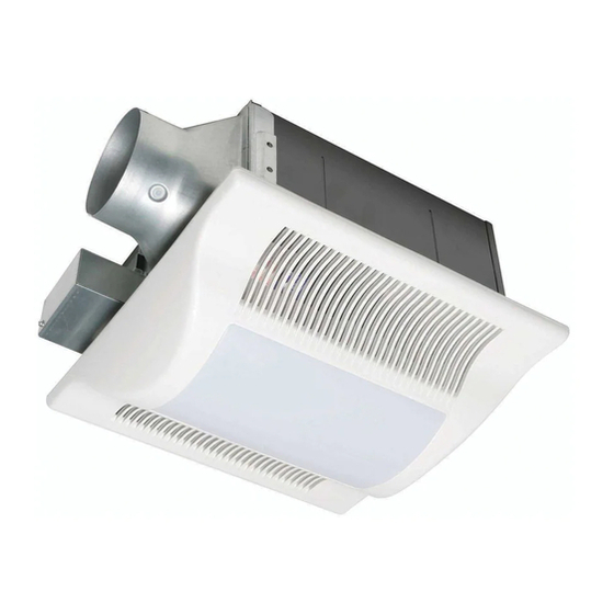
Installation bracket Description These Panasonic ceiling mount ventilating fan models use a sirocco fan driven by a capacitor motor. The motor is designed to have an extended service life with reduced energy consumption. It also incorporates a thermal-cutoff for safety. The grille can be quickly detached from the main unit. A damper for preventing air counterflow is provided. -
Page 3: Specifications
Dimensions continued (13" Specifications Model Air direction FV-07VQL3 FV-08VQL3 Exhaust FV-11VQL3 * At 0.0" Static pressure, (Pa) Unpacking Unpack and carefully remove unit from carton. Refer to the Supplied components list to verify that all parts are present. General safety information Do not install this ventilating fan/light combination in ducts where air temperature may exceed 104 F. - Page 4 General safety information continued Protect the power cord from sharp edges, oil, grease, hot surfaces, chemicals, or other objects. Do not kink the power cord. Do not install the unit where ducts are configured as shown in Fig. A. Provide suction parts with proper ventilation. This unit is acceptable for use over a bathtub or shower when installed in a GFCI protected branch circuit.
- Page 5 Installation (Joist mounting installation) CAUTION: Remove the bracket cover by loosening 4 (M4x6) screws before installation Disconnect plug connector from receptacle before starting installation. Remove adapter from body and fix to ceiling joists using long screws (M4X30). Slide the installation bracket * into slot next to the junction box.
-
Page 6: Installation I (Joist Mounting Installation)
Installation (Joist mounting installaton) continued Wiring Diagram Light unit Fan unit Ballast Capacitor Black Motor Black White Green Green Junction box Night Lamp Slide 4" dia. duct onto adapter and secure with tape. Remove ceiling section. CAUTION: Mount junction box cover carefully so that lead wires are not caught. - Page 7 Installation (Joist mounting installaton) continued IMPORTANT: Make sure that body "Claws" are properly inserted into adapter slots. In case body and blower are installed separately. Remove 3 screws. (Fig.6-1) Remove blower section. (Fig.6-2) Blower section Insert fan body into ceiling. (Fig.
- Page 8 Installation (Joist mounting installaton) continued Insert plug connector I to receptacle I. Fix fan body to ceiling joists using long screws (M4X30) in horizontal or vertical direction. Insert the plug connector II , plug connector III into the receptacle II, receptacle III respectively, and attach the light unit to the fan unit with 3 plastic screws (M4X13) and one short screw I (M4x12) .
-
Page 9: Installation Ii (Wooden Header Installation)
Installation (Wooden header installaton) Before installation, secure adapter to fan body using two thumb screws. Insert the plug connector II and plug connector III into the receptacle II and receptacle III respectively. Install the light unit to the fan body by using plastic screws (M4x13) and one short screw I (M4x12). -
Page 10: Installation Iii (Between Joist Mounting Installation)
Installation (Between joist mounting installation) 1. Before installation, secure adapter to fan body by using two thumb screws. 2. Insert the installation bracket III into slot of the adapter side. 3. Insert the installation brackets I and IV into slot. Thumb screws (Fig. - Page 11 Installation (Between joist mounting installation) continued 4.Insert the fan body between joists. Make sure the fan body is level and square (perpendicular) with the joists. Keep the flange and joists on same level. CAUTION: Joist spacing A should be between 350mm (13 7/8") and 430mm (17").
- Page 12 Installation (Between joist mounting installation) continued 7. Secure installation bracket I and IV to the fan body using short screw I (M4X12) and short screw II (M4X10). 8. Slide the circular duct onto the adapter and secure with tape.Remove the junction box cover and secure conduit to junction box knockout hole.(7/8 inch) Refer to wiring diagram on page 6.
- Page 13 Installation (Between joist mounting installation) continued 11. Insert a spacer to metal plate of the fan case and three spacers to the light unit. Insert the plug connector II and plug connector III into the receptacle II and receptacle III respectively. Attach the light unit to the fan unit by 4 long screws (M4x30).
-
Page 14: Installation Iv (Ln Existing Construction)
Install ventilating fan. 2. Disconnect the connector II or connector III of light unit. Change the fluorescent bulbs (Panasonic FDS 13E (Fig. 28) 27.U/2, 13W or FQ13E 41.U/2, 13W or FQ13E 35.U/2, 13W) or the 4W incandescent lamp, connect the connector II or connector III and replace the grille. -
Page 15: Maintenance Ii (Cleaning)
Maintenance (Cleaning) WARNING: Disconnect power source before working on unit. Routine maintenance must be done every year. CAUTION: 1. Never use gasoline, benzene, thinner or any other similar chemicals for cleaning the grille and the ventilating fan. 2. Do not allow water to enter motor. 3. -
Page 16: Product Service
AUTHORIZED INDEPENDENT SERVICE CENTERS is maintained to support your product's warranty. (In the U. S.A., call 1-866-292-7292 to locate the Panasonic Authorized Service Center nearest you.) PANASONIC CONSUMER ELECTRONICS COMPANY One Panasonic Way, Secaucus, NJ, 07094 PANASONIC CANADA INC.