
Related Manuals for Acer AT4250B


Summary of Contents for Acer AT4250B
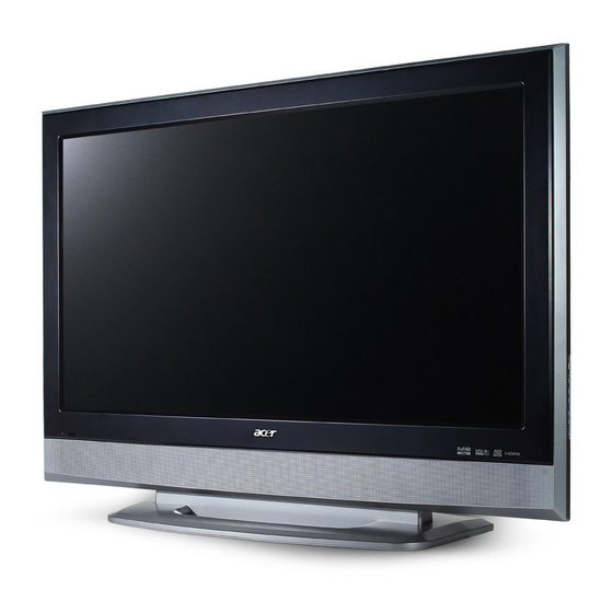
- Page 1 Acer AT4250B LCD TV Service Guide Service guide files and updates are available on the ACER/CSD web. For more information, please refer to http://csd.acer.com.tw PRINTED IN CHINA...
-
Page 2: Revision History
Revision History Please refer to the table below for the updates of LCD TV AT4250B service guide. Date Chapter Updates 2007/10/29 Chapter 1 ~ 4 1st edition... - Page 3 Copyright Copyright®2007 by Acer Incorporated. All rights reserved. No part of this publication may be reproduced, transmitted, transcribed, stored in a retrieval system, or translated into any language or computer language, in any form or by any means, electronic, mechanical, magnetic, optical, chemical, manual or...
- Page 4 Any Acer Incorporated software described in this manual is sold or licensed “as is”. Should the programs prove defective following their purchase, the buyer (and not Acer Incorporated, its distributor, or its dealer) assumes the entire cost of all necessary servicing, repair, and any incidental or consequential damages resulting from any defect in the software.
- Page 5 Conventions The following conventions are used in this manual. SCREEN MESSAGES Denotes actual messages that appear on screen. Gives bits and pieces of additional information related to NOTE the current topic. Alerts you to any damage that might result from doing WARNING or not doing specific actions.
- Page 6 DIFFERENT part number code to those given in the FRU list of this printed Service Guide. You MUST use the list provided by your regional Acer office to order FRU parts for repair and service of customer machines.
- Page 7 Chapter 1 System Specification Specification LCD Panel Max. resolution: 1920x1080 20 CCFTs Backlight system Display area: 42inches Display color: 16.7 M colors Input Signal: 2-ch LVDS Contrast ratio: 1200:1 ( Typical ) Dynamic Contrast ratio: 6000:1 ( Typical ) Brightness: 500 Cd/m² ( Typical ) Response Time: 6.5 ms Viewing angle: 88°...
- Page 8 Build in Teletext functions Build in Dynamic adaptive smoothing filter Build in Dynamic temporal frame-filtering Noise Reduction Build in Dynamic motion and edge adaptive De-interlacing Film mode 3:2 & 2:2 pull down Screen display model 16:9 / 4:3 / panorama / zoom / PIP / POP Mechanical VESA mounting holes Compatibility...
- Page 9 System Block & Wiring Diagram PANEL INVERTER I/O Board POWER Tuner Board MAIN Board YPbPr (RCA) CVBS (RCA) Audio R,L IR & power button Bd Key & Earphone Board SPEAKER-L SPEAKER-R Chapter1...
- Page 10 LCD Main Board Block Diagram Chapter1...
-
Page 11: Remote Control
Remote Control Chapter1... - Page 12 Key Functions Remote Function description Remark (for R/C for Europe Key Functions cardreader) Power Power On/Off Display Display Channel and Input Source Mute Mute On/Off TV Turner Component Component1/Component2 AV1/AV2/AV3 Sleep Sleep Timeer Off 15/30/45/60/90/120 Frozen Picture frozen on/off Wide Scaling Mode ( 4:3 /16:9 /Panorama /Letterbox ) Menu Open Menu or leave Menu...
- Page 13 Turn teletext mode on/off Subtitle Show subtitle on the screen Colour button to operate the teletext Colour button to operate the teletext Colour button to operate the teletext Colour button to operate the teletext Empowring Key Activate Acer empowering feature Chapter1...
-
Page 14: Hardware Specification And Configuration
Hardware Specification and Configuration Electro/Optical Model AT4250B Panel specification Resolution(pixels) 1920x1080 Brightness(min.) 500 cd/m² Contrast ratio(min.) 1200:1(Typ.) Display color 16.7 M Viewing angle 176(H)/176(V) Response(typ.) 6.5ms Power supply Input 90-264 V, 47-63 Hz Max. power Consumption 291W Power saving Mechanical Dimensions(WxHxD mm) 1070.96*796.44*310.73... -
Page 15: Firmware Specifications
Firmware Specifications Preset Mode for VGA Input 16 factory pre-set modes for VGA inputs are saved during the manufacturing process. Please press "Volume-" + "Channel+" + "POWER" to enter the LCD TV factory mode. Preset Hor. Freq. Vert. Freq. Vertical Pixel Format Hor. -
Page 16: Performance Specifications
1280x768 60 1360x769 60 1280x720/50 1280x720/60 576P/50 1920x1080i/50 1920x1080i/60 This LCD TV shall have 10 or more user modes for user to creat own timing. Power Saving While VGA is selected to be input, this LCD TV is equipped with a power-management according to VESA DPMS. - Page 17 Set contrast and brightness at max. Cold: 14000 degree K(x=263,y=273) on x and y value. Standard: 9300 degree K(x=283,y=297) on x and y value. Warm: 6500 degree K(x=312,y=329) on x and y value. Display Area, Phase, Center and Tilt Display Area: 27 inches diagonal H-Phase: Less than 1.5mm V-Center:...
-
Page 18: Overall Dimensions
Line Fuse The AC input shall be fused and become electrically open as a result of an unsafe current condition. This fuse is inside the power supply converter and is not user replaceable, and must be returned for replacement. This fuse shall be well selected to handle inrush current for all combinations of line voltage and frequency. Hot plug and power on/off sequence Once hot plug occurs, at the very first time, the initial current should be limited at 2.3 amps or lower when power off. -
Page 19: Environmental Requirements
Environmental Requirements This display shall meet the following environmental requirements under normal operating conditions. Operating 25° ± 5° for Purity, White Point, Mis-convergence, Luminance measurements and White uniformity measurement Operating temperature: 0°C to 35°C Operating humidity: 10 % to 90 % ( non-condensing ) Storage and Shipping Storage temperature: -20°C to 60°C Shipping temperature: -20°C to 60°C... -
Page 20: Vibration Test
Altitude Units tested at an altitude up to 12,000 feet must operate at normal conditions without exhibiting abnormal behavior such as arcing or shutdown. Operating altitude: 0 to 12,000 feet Shipping altitude: 0 to 40,000 feet Storage altitude: 0 to 40,000 feet Vibration Test The packaged display shall be capable of passing sinusoidal vibration test as specified in follows. - Page 21 Drop Test The packaged display shall be capable of passing drop test as specified in following specification without any measurable degradation in performance or detectable mechanical or cosmetic damage. Filter: 330 Hz Dropping way: 1 corner, 3 edges, 6 flats Dropping Height: follow the below table Mass(kg) Drop Height(cm)
- Page 22 For VGA input: Product Revision For HDMI input 1 Product Revision Chapter1...
-
Page 23: Machine Disassembly And Replacement
Machine Disassembly and Replacement General Information This chapter contains step-by-step procedures on how to disassemble the AT4250B series for maintenance and troubleshooting. To disassemble the TV, you need the following tools: Wrist grounding strap and conductive mat for preventing electrostatic discharge... - Page 24 1. Release 6pcs screws from base and take off it. 2. Release 10pcs screws from rear cover. 3. Release 10pcs screws from rear cover. 4. Release 6pcs screws from stand brackets. Chapter2...
- Page 25 5. Release 6pcs screws from HDMI and IO joint. 6. Release 6pcs screws from PCB shielding. 7. Release 8pcs screws from PCB shielding. 8. Release 8pcs screws from left and right speakers. 9. Release 2pcs screws from IR/B. 10. Release 3pcs screws from Keypad/B. Chapter2...
- Page 26 11. Release 9pcs screws from Boards. 12. Release 7pcs screws from boards. 13. Release 4pcs screws from Power/B. 14. Release 7pcs screws from panel brackets. Chapter2...
- Page 27 15. Release 5pcs screws from chassis and LVDS cable. 16. Rlease 11pcs screws from bezel and brackets. 17. Release 4pcs screws from top panel brackets. 18. Release 4pcs screws from buttom panel brackets, then take off them. Chapter2...
-
Page 28: Troubleshooting
Chapter 3 Troubleshooting Use the following procedure as a guide for Acer LCD TV AT4250B series problems. Note: The diagnostic tests are intended to test this model. Non-Acer products, prototype cards, or modified options could occur false errors and invalid system responses. - Page 29 TV NO PICTURE ISSUE Start Connect with AC power code and RF Upload F/W cable To switch on Power Power button LED Replace color with red Power Board Replace On/Off LED to Swap test fixture LED to switch button show red Power Board bright board...
- Page 30 POOR PICTURE QUALITY Start Connect with AC power code and RF Upload F/W cable or other source signal Press Power On/Off Button to LED color show green Picture right Swap the test Check the LVDS Poor picture fixture cable is well Main Board Replace Poor picture...
- Page 31 NO TV SIGNAL ISSUE Start Connect with AC power code and RF Upload F/W cable Press Power On/Off Button to LED color show green No TV signal Swap test fixture No signal Tuner Board Replace broken Main Board Replace Tuner Board Chapter3...
- Page 32 Capter3...
-
Page 33: Fru (Field Replaceable Unit) List
Note: To scrap or to return the defective parts, you should follow the local government ordinance or regulations on how to dispose it properly, or follow the rules set by your regional Acer office on how to return it. - Page 34 PARTS PART NAME DESCRIPTION TVE PART NO. ACER PART NO. Accessory REMOTE REMOTE CONTROL EURT54B005 GP DQ7T54B0001 25.M3507.001 BATTERY LR03GW/2SK (ALKALINE 1.5V) GP AHDALR03006 23.M480E.002 BATTERY BATTERY LR03(SN) (ALKALINE,1.5V) GP AHDALR03120 23.M09V7.012 BOARD MAIN/B HV4E M/B ASSY(FOR HV4A)CMO L07 GP 21HV4EMB021 55.M8207.001...
- Page 35 RATING LABEL RTG LABEL HV4(HCHV4002,3B)ACER AT4220 GP HCHV4002016 MISCELLANEOUS CMO GASKET LVDS CMO GASKET LVDS HX4(GBHX4P01,3A)GP GBHX4P01017 CMO GASKET UP CMO GASKET UP HX4(GBHX4P02,3A)GP GBHX4P02013 CMO GASKET DOWN CMO GASKET DOWN HX4(GBHX4P03,3A)GP GBHX4P03010 CMO GASKET POWER CMO GASKET POWER HX4(GBHX4P04,3A)GP...
-
Page 36: Exploded Parts List
Exploded parts list ITEM DESCRIPTION TVI PART NO. ACER PART NO. HV4E LCD-BEZEL ASSY (FHD) GP 36HV4LBTN12 60.M3507.001 AH4T BACK COVER ASSY GP 47AH4BC0I06 60.M34V7.002 HV4 STAND ASSY GP 27HV4SATN07 60.M34V7.003 STAND COVER HX4(EAHX4004,REV3B) GP EAHX4004012 42.M34V7.001 AV3 FRAME HV4(EBHV4002,REV3A) GP EBHV4002015 42.M3507.002... - Page 37 SCREW M4*22-B(BNI+WASHER+SPRING) GP MM40220BK82 86.M34V7.002 SCREW T3*12-P(BNI+WASHER) GP MS30120PCT3 86.M3507.004 SCREW T3*8-B(BNI) GP MT30080BJ20 86.M08V7.007 Chapter4...