Advertisement
Quick Links
INSTALLATION AND MAINTENANCE INSTRUCTIONS
WARNING: Raritan Engineering Company, Inc. recommends that a qualified person install this product. Equipment
damage, injury to personnel or death could result from improper installation. Raritan Engineering Company,
Inc. accepts no responsibility or liability for damage to persons, equipment or injury or death that may result
from improper installation or operation of this product.
INTRODUCTION
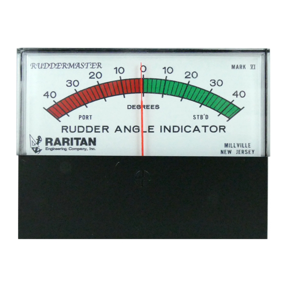
The Ruddermaster indicates at a glance how far the rudder
is from a straight ahead position. As the steering wheel is
turned, the sending unit communicates the angle of the
rudder to the calibration box. The calibration box transmits
the rudder's position to the meter. The Ruddermaster can
be used both as a steering aid and to monitor auto pilot
systems.
A complete unit consists of four components:
1. Meter with 5' (1.53m) of two conductor cable
2. Sending Unit with 30' (9.15m) of connecting
wire
3. Calibration Box
4. Actuator Rod with Ball Joints
Repeater Units with 15' (4.58m) of connecting wire can be
used for additional rudder angle displays.
NOTE: Additional lengths of connecting wire may be
ordered.
INSTALLATION PROCEDURE
READ ALL STEPS BEFORE PROCEEDING
Important Installation Note: Sending unit arm must
be re-positioned before installation and calibration, see
info sheet (L420) included with Sending Unit.
MK445, MK5, or MK6 meters are not water proof.
Mount where meter will not be exposed to
weather, wash down spray, or direct sun-
light. MK2**, MK2B** AND MK3B**ARE
SPRAY PROOF (IP64).
MOUNTING Meter and/or Repeater:
1. Using the templates provided, cut out the appropriate
size hole.
2a. MK445 - Secure the unit by attaching the faceplate to
the mounting surface.
NOTE: Use only stainless steel or chrome plated brass
screws.
2b. MK5 and MK6 - Drill four holes for the studs
attached to each corner of the meter. Secure using the
nuts provided.
2c. MK2**, MK2B** and MK3B** - Mount meter in
RU DDERM AST ER
Rudder Angle Indicator
hole and secure using meter bracket and hardware
supplied. Connect two conductor cable to the meter.
NOTE: Red wire must be connected to positive (+)
terminal on meter. Connect bulb wiring to power
source.
The Calibration Box:
Mount behind the panel within reach of the wires attached
to the meter and sender wires. A protected area where
wires can be easily connected is best.
The Sending Unit:
WARNING:
TURNING THE WHEEL WITH
CENTERING SCREW IN PLACE WILL DAMAGE
THE SENDING UNIT. CORRECT POSITIONING
OF THE SENDING UNIT IS CRUCIAL TO AN
ACCURATE METER READING.
1. Drill a #21 hole 2 11/16" (6.83cm) from center of the
rudder post. Tap hole with 10-32 thread. Mount ball
joint at one end of the actuator into the hole.
2. Center rudder(s) in the straight ahead position. (This
can best be done by marking the steering wheel while
under way.)
Use the following criteria when selecting a mounting site
for the sender:
• Protected from bilge water immersion or splashing.
Sending units are not waterproof.
• The sending unit arm is on the same horizontal plane as
rudder arm (when looking from the side).
• The sending unit arm and the rudder arm, when centered,
are at right angles to the actuator rod. (The sending unit
arm will always remain parallel to the rudder arm.) See
Fig. #1.
• The distance between the rudder arm and the sending
unit arm must accommodate the range of adjustment of
the actuator rod.
• To maintain an accurate meter reading the rudder arm
and the sending unit arm should be parallel (when
looking from above). See Fig. #1. (It may be necessary
to add a spacer.)
3. Once the sending unit is mounted, attach the actuator
**Specify voltage
Advertisement

Related Manuals for Raritan RUDDERMASTER


Summary of Contents for Raritan RUDDERMASTER
- Page 1 Rudder Angle Indicator INSTALLATION AND MAINTENANCE INSTRUCTIONS WARNING: Raritan Engineering Company, Inc. recommends that a qualified person install this product. Equipment damage, injury to personnel or death could result from improper installation. Raritan Engineering Company, Inc. accepts no responsibility or liability for damage to persons, equipment or injury or death that may result from improper installation or operation of this product.
- Page 2 Unit Black back illumination lighting: connect White one wire to the panel light switch FIG. #2 Wiring the Ruddermaster with one Meter positive (+) and the other wire to negative (-). NOTE: Slight adjustment can be made by REPEATER WIRING: loosening set screw in the sender arm and rotating the sender shaft.
- Page 3 Black check the potentiometers in the sending unit White and calibration box with an ohmmeter. Fig. #3 Wiring of Ruddermaster with two meters Checking the potentiometer in the sending screw as far as it will go counter clockwise. The unit: ohmmeter scale should indicate 0.
- Page 4 1.TO OBTAIN WARRANTY SERVICE, Consumer must deliver the product prepaid, together with a detailed description of the problem, to Raritan at 530 Orange St., Millville, N.J. 08332, or 3101 SW 2nd Ave Ft. Lauderdale, FL 33315. When requesting warranty service, purchaser must present a sales slip or other document which establishes proof of purchase.