Table of Contents
Advertisement
Quick Links
Advertisement
Table of Contents

Related Manuals for JetCat SPH5


Summary of Contents for JetCat SPH5
- Page 1 6216440 Copyright © JetCat USA, LLC US Patent # July, 2007 Instruction manual V5.0 ECU JetCat SPH5 JetCat USA, LLC 4250 Aerotech Center Way Building G Paso Robles, CA 93446 (805) 226-8700 Voice (805) 226-8742 FAX www.jetcatusa.com MADE IN GERMANY...
- Page 2 JetCat USA shall not be liable for its sole negligence. JetCat USA shall not be liable for its willful misconduct. JetCat USA shall not be liable based on any theory in strict liability in tort. JetCat USA shall not be liable for any alleged breach of warranty, whether express or implied, of any nature whatsoever, whether a warranty of fitness for a particular use, merchantability, or otherwise.
- Page 3 5. Sale By Buyer to Other Party. Buyer agrees to fully inform any person to whom he/she sells or transfers the Model Engine, concerning the handling, use, and operation of the Model Engine, and agrees to give all operating instructions to such person, at or before the time of sale or transfer.
- Page 4 JetCat USA shall not be liable for any other losses or damages. 6) Upon request from JetCat USA, the Buyer must prove the date of the original purchase of the Model Engine by a dated bill of sale or dated itemized receipt.
-
Page 5: Table Of Contents
........................28 WITCH ESCRIPTIONS GSU LED D ........................28 ESCRIPTIONS THE LED I/O BOARD..........................29 JETCAT ECU VERSION 4.0 INTRODUCTION ................. 30 SETTING UP THE ECU.......................... 31 ....................31 ALIBRATE THE TEMPERATURE PROBE “L RC”....................32 ETUP FAILSAFE MODE AND... - Page 6 “LEARN R/C”. TEACH THE ECU TO THE R/C SYSTEM .............. 34 TEST FUNCTIONS..........................37 TURBINE STARTING / RUNNING ...................... 37 GSU......38 ANUAL STARTUP WITHOUT USING THE TRANSMITTER DIRECTLY FROM THE TURBINE STOPPING / COOL DOWN ....................39 ............................39 ANUAL ......................
- Page 7 SOME OTHER NUMBER HIS IS THE HEAD SPEED AND TAIL ROTOR SPEED IN THE COMPUTER AT THE MOMENT O CHANGE THE HEAD SPEED TO THE DESIRED VALUE PRESS AND HOLD THE CHANGE VALUE – AND PRESS THE KEYS HIS WILL CHANGE THE HAFT VALUE WHICH WILL IN TURN ALTER VALUE...
-
Page 8: Introduction
Introduction Welcome to the Jet Age of model aircraft! JETCAT USA is pleased to sell, support and service the JetCat turbine engine and greatly appreciates your purchase. We hope the JetCat engine brings you many days of pleasurable flying. Obviously, model turbine aviation - despite all the apparent fun involved - is serious business. -
Page 9: Safety Precautions
= 25 feet Behind the turbine = 15 feet In case of a mishap, fire extinguishers should be on hand at all times. JETCAT USA recommends the CO/2 variety. Powdered extinguishers will contaminate the precision components, upsetting the integrity of the turbine. -
Page 10: The Checklist
The Checklist Before Running the Turbine • Charge ECU Battery • Prepare fire extinguisher • Check fuel lines and filter. Make sure they are clean with no restrictions • Check that the fuel tank vent is unobstructed • Mix 5 % oil in fuel (i.e.: 1 quart per 5 gallons of kerosene) •... -
Page 11: Fuel / Fuel Care
Fuel / Fuel Care The JetCat engine can use deodorized kerosene, 1-K kerosene or Jet-A1 for fuel. Fuel must be mixed with 5% synthetic turbine oil. Example formula: 1 quart of oil in 5 gallons of fuel. JetCat recommends Aeroshell 500 turbine oil. -
Page 12: Hopper Tank
Hopper Tank A hopper tank is recommended, between the main fuel tank and the engine. JetCat USA highly recommends the BVM UAT for the hopper tank! Always use the filter between the fuel pump and the solenoid valve as shown in the diagram. -
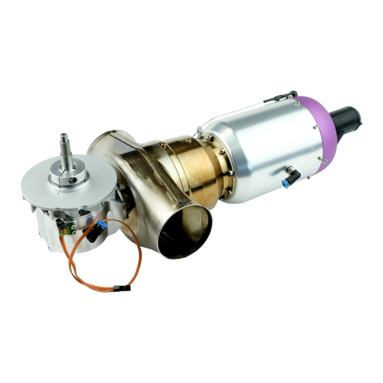
Page 13: Sph5 Introduction
The generally available high energy or torque power band of turbine engines, is now accessible through the SPH5 turbine reduction gear. Therefore, as in the full scale industry, turbine engines will play a more prominent role in the RC scale helicopter world. - Page 14 Checking of RPM sensor for the second stage turbine: As soon as the sensor for the second stage turbine has been connected to the Exp connector on the ECU it is ready to be tested. is ready to be tested. Connect the GSU with LED- Board and switch the radio on.
- Page 15 The sequence of these connections can be changed as required (parallel bus system) Connection - diagramm (Die Reihenfolge der Verbindungen spielt keine Rolle --> paralleles Bussystem) "phone"- cable "phone"- cable (Verbindungsschema) ("Telefonkabel") ("Telefonkabel") Jet-tronic (optional) Remote - GSU RS232 Adapter Standby / Man.
- Page 16 Connection - diagramm (2/2) (Verbindungsschema) ECU bottom-view (von unten) Fuelpump Jet-tronic -II- P80 To turbine (3 wire cable) (Kraftstoffpumpe) (Zur Turbine 3-adriges Kabel) Microcomputer-Control 1 or 2 connections Gas valve to the Rx (Propane Fuel pump Fuel valve...
-
Page 17: Turbine Battery
Connect fuel Connect gas valve to valve to bottom bottom connector below connector airspeed input Turbine battery All the components ( starter, glowplug, ECU, fuel pump etc) are powered by a single 6 cell battery which is connected directly to the ECU. Caution It is not permitted to under any circumstances to fit a switch in the battery cable. -
Page 18: Fuel System / Lubrication System Connection Diagram
Please note that not all types of turbine oil mix with petroleum. Fuel system / lubrication system connection diagram Caution! Mount this pipe at least 5cm from the engine/exhaust pipe and secure it so it cannot possibly touch hot parts! Gearbox Reducer/filter Fuel feed... -
Page 19: Fuel System Connection Diagram
Tank Fill 1/4 inch section of 4 mm (Kerosene) tubing acts as an adapter for large BVM UAT tubing Note: All tubing 4mm(except as noted) The UAT is available from JetCat USA,LLC or Bob Violett Models, Florida (407) 327- 6333. -
Page 20: Fuel Pump Adjustment
Fuel pump adjustment After the turbine has ignited on propane, the starter motor further accelerates the turbine. At approx. 5000 RPM, the fuel pump is automatically started at minimum power by the ECU. Beginning from this first pump start voltage, the fuel flow is then slowly increased by increasing the pump voltage. - Page 21 Pump start voltage is adjusted too low: If the pump start voltage is adjusted too low, the pump may not start to turn ( the red “pump running” LED is illuminated, but the pump is not turning). This can result in the turbine, after ignition on propane, running an unusual long time and not picking up RPM.
-
Page 22: Starting Gas Diagram
Starting Gas Diagram Starting Gas 3mm tubing to turbine Shutoff Valve 4mm tubing 4 -> 3mm tubing adapter 4mm tubing Filter 4mm tubing Petcock On Board (Starting Gas Vent) Starting Gas Tank Keep Line Short ! One Way Festo (Note markings!) Plastic Barb (To Offboard Gas Fill) Coleman... -
Page 23: Filling The Starting Gas Tank
Filling the Starting Gas Tank: Only use a propane/butane mix for starting gas. JETCAT USA recommends Coleman POWERMAX fuel (or a mix of propane butane 60/40%). POWERMAX is available at sporting goods stores or from JETCAT USA. -
Page 24: Mounting The Turbine
Mounting the Turbine A two-piece, aluminum mounting bracket is included with the turbine. Place the bracket around the turbine, with the glow plug situated within the slot of the smaller bracket piece. This will help stabilize the engine along the thrust axis. The glow plug must be in the vertical position, when mounted in your model (+/- 75°... -
Page 25: Power Supply
300-400 mah. This includes starting and cool down. The ECU NiCad battery must be recharged after two (2) flights! JETCAT USA recommends recharging after every flight, making it a routine that is not overlooked. The battery should be cycled periodically, to prevent NiCad memory problems that lower the battery’s capacity. - Page 26 Note: 2 coils pulled out 90° from the body If you have been enjoying good auto starts, and suddenly you notice that your turbine does not start immediately on the first starting gas cycle, check the glow plug. The plugs last so long that we sometimes forget that they can finally wear out!
-
Page 27: Ground Support Unit (Gsu)
Ground Support Unit (GSU) The GSU serves as a terminal for displaying and programming turbine parameters. It may be connected or disconnected at any time. The real time nature of the ECU allows the operator to adjust the turbine’s parameters, even when the turbine is running. -
Page 28: Gsu Switch Descriptions
GSU Switch Descriptions Explanation Directly displays the Info menu (Hotkey). Info Directly displays the Run menu (Hotkey). Directly displays the Limits menu (Hotkey). Limits Directly displays the Min/Max menu (Hotkey). Min/Max Select Menu When the Select Menu key is pressed and held, the ◄ - / ►+ keys are used to select another menu. -
Page 29: The Led I/O Board
The LED I/O Board The LED I/O (Input/Output) board is a connection point for the data bus and a display for the current status of the ECU. The board should be mounted with the LED’s visible and the data bus connector accessible for plugging in the GSU. The connector facing opposite of the LED’s is attached to the ECU. -
Page 30: Jetcat Ecu Version 4.0 Introduction
This is the most significant update for the American market since our introduction of the JetCat engine, December 1998. This update replaces the processor board in the ECU with a new, totally redesigned board, utilizing the Hitachi H8 16 bit micro-controller. This very fast and powerful micro-controller allowed us to expand our already rich set of features and has a much larger capacity to expand in the future. -
Page 31: Setting Up The Ecu
Setting up the ECU These are the first steps you need to complete before operating the v4.0 ECU. Make sure your batteries are charged, the ECU is off and the GSU is connected. Do not perform the calibration of the temperature probe if this is a new engine. Temperature probe calibration is for ECU updates only. -
Page 32: Setup Failsafe Mode And "Learn Rc
”Learn R/C” are not allowed under AMA rules.) Setting the failsafe for JR PCM receivers – Call JetCat USA for failsafe setup procedures for other radio brands. If you look at the following servo travel graph, you can see how the ECU detects a failsafe condition. -
Page 33: Time In Failsafe (Seconds)
IMPORTANT: IF YOU CHANGE YOUR TRANSMITTERS FAILSAFE AGAIN IN THE FUTURE, YOU MUST REDUE THE FOLLOWING INSTRUCTIONS AGAIN. • First, set your transmitters travel parameter to 100% for low throttle and 100% for high throttle. On the JR 10X transmitter, use function 12 to access the throttle travel. •... -
Page 34: Failsafe Timeout
Setting for the period before the ECU will go into the Failsafe Failsafe Delay mode and reduce the throttle to the preset FailSafeRPM. After :0.1 the FailSafeTimeOut below, the engine would then shut off. This maybe programmed from 0.1 to 20 seconds (Default = 0.1 seconds). Failsafe timeout Setting for how long the turbine will run in a failsafe condition FailSafeTimeOut... - Page 35 Release Select Menu only after the three LED’s display the following blink sequence: Blink Sequence Standby/Man. Yellow Pump running ..Green The GSU display will simultaneously read: Release key to: - learn RC - 4. This procedure enables a system mode, whereby the control positions can be learned by the ECU.
- Page 36 7. Advance the throttle control channel to maximum. Press Select Menu or the LED I/O board switch again, to store the R/C system’s pulse width for the turbine full power position. The yellow Standby LED will turn off and the green OK LED will illuminate again, indicating that the turbine full power data has been set correctly.
-
Page 37: Test Functions
Test Functions The new Test Function Menu For owners of our previous ECU, the Manual mode is no longer implemented. Instead, a new expanded set of test functions are available from the Test–Functions Menu. This menu is selected while pressing the Select Menu key, press the ◄ - or ► + key until the menu is displayed. -
Page 38: Manual Startup Without Using The Transmitter Directly From The Gsu
attempts. If the turbine does not ignite, during a 30-second period of attempts, the process is aborted and the green OK LED will blink. 4. As soon as ignition occurs, the yellow Standby LED will illuminate and the starting motor is re-engaged to accelerate the turbine. At approximately 5000 RPM, the fuel pump switches on and the red Pump running LED illuminates. -
Page 39: Turbine Stopping / Cool Down
Turbine Stopping / Cool Down To shut off the turbine, there are two methods: Manual Off Turbine immediately turns off! At anytime, the turbine can immediately be switched off manually by bringing the throttle stick and trim to their minimum positions Automatic Cooling Process After the turbine spins down from Manual Off, the starter motor will periodically spin the turbine rotor, if the Exhaust Gas Temperature is above 100°... -
Page 40: Turbine Running States
Turbine Running States The JetCat turbine progresses through several operating states, from ignition to the cool down process. The transitions of these states are automatically controlled by the ECU and by user commands. The current value is always displayed on the GSU, under the STATE selection in the RUN menu. - Page 41 Glow plug is switched on and the starting gas valve is opened. The Ignite... GSU’s red Ignition LED is illuminated when the glow plug switches on. The ECU now pauses until ignition occurs and will remain in this condition until at least one of the following criteria is met: •...
- Page 42 Slow Down During this state, the fuel shut-off valve is closed and the fuel pump is stopped. The green OK LED blinks, indicating Slow Down This condition will continue, until all of the following parameters are met: • Turbine speed less than 800 RPM •...
-
Page 43: Explanation For Turbine Shut Down
Explanation for Turbine Shut Down In the run menu, state selection, are the following explanations for the last shut down condition of the turbine. Code Value Explanation Throttle stick and throttle trim moved to the minimum position. R/C Off Turbine running over temperature. Exceeded high OverTemp temperature parameter and time out. -
Page 44: Menu Structure
Menu Structure All similar data and running parameters are grouped in separate menus. Menus can be displayed and their values modified (where accessible), by using the GSU. Menu Selections • Run menu • MIN/MAX menu • RC-Check menu • Info menu •... -
Page 45: The Run Menu
The RUN Menu As soon as the ECU is switched on, the default run menu is displayed. Before starting the engine, the default display appears like this. The first line displays the temperature in degrees Celsius, glow plug bad icon (flashing), remote mode icon, failsafe icon and RPM in thousands. -
Page 46: The Min/Max Menu
In addition to the default display, the following selections can be monitored on the upper display line. Use the ◄ - / ►+ keys alone for selecting the different parameters. Value Explanation See above for description. Default Display Current pump voltage. U-Pump / Current RPM. -
Page 47: The R/C Check Menu
The R/C Check Menu All parameters in this menu are for informational purposes only and will vary in accordance with R/C input. Value Explanation Position of the throttle stick (by percentage, 0-100%). An ‘F’ signals StickPuls a failsafe condition. Position units of the throttle stick. Throttle% Displays the number of times the receiver went into failsafe during FailSafe Count... -
Page 48: The Statistic-Menu
Last stored Off condition. Last Off Cond Maximum temperature during the last run. Last MaxTemp Minimum temperature during the last run. Last MinTemp Average temperature during the last run. Last AvgTemp Average temperature during the last run at maximum RPM. Last MaxR AvgTmp Maximum temperature during startup during the last run. -
Page 49: The Test Functions Menu
The Test Functions Menu The Manual mode is no longer implemented. Instead, a new expanded set of test functions are available from the Test–Functions Menu. To test the selected component, press the Change Value/Item key. To change the fuel pump or glow plug voltage when testing, while pressing the Change Value/Item key, press the ◄... - Page 50 Limits Menu, continued Value Explanation Delay before the failsafe function is activated. FailSafe delay Range = 0.1 to 20.0 seconds. Delay before turbine shuts off because of a failsafe. FailSafeTimeOut Range = 0.1 to 20.0 seconds RPM the turbine will throttle to during a failsafe time out period. FailSafeRPM Range = Minimum RPM to Maximum RPM If enabled, after turbine is started and throttled up, the starting gas...
-
Page 51: Helicopter Head Speed Control Menu
Helicopter Head speed control menu There is a sub menu in the turbine limits menu for altering the gear ratio of the helicopter so as to set the head speed. Access it by entering the turbine limits menu as before, then press limits and + simultaneously and release. U-accel R1 :0.225 U-idle R1... - Page 52 switch. This should be programmed to give low, medium and high output pulses to one channel and the Aux lead from the ECU should be plugged into that channel. Set up the head speed as normal for R1 as above. Press and hold the LIMITS button and press the SELECT MENU button until you get to TURBINE LIMITS.
-
Page 53: Troubleshooting
Troubleshooting Most frequent errors. Cause and remedy: Problem Cause Remedy Starting gas system has a leak Check starting gas system for Turbine doesn't or bad connection. leaks and poor connections. ignite Starting gas pressure is low. Fill starting gas tank; fly in May be caused by insufficient warmer conditions quantity of gas or low outside... -
Page 54: Reason For Shut-Down
Air in fuel feed lines. Air leaks in fuel system. Turbine ignites, Examine all Festo fittings, but the start nipples, clunk, filter, etc. process is Check for fuel filter clogs. discontinued. Fuel pump not running. Test the pump in manual mode (as soon as the red Pump running LED illuminates, the fuel pump must run!). - Page 55 3. As long as you do not power-down the system, you can down view the entire flight using the RS-232 adapter and a PC. If the off condition is "POWER-FAIL" then the data is not valid. This occurs if the ECU or receiver battery was disconnected or was intermittent or if the receiver power goes lower than 3 volts.
-
Page 56: Maintenance
Each JetCat has a prescribed maintenance interval. After approximately 25 hours, the engine should be returned to JETCAT USA (along with the ECU and fuel pump), for service. The total running time of the turbine can be accessed and monitored through... -
Page 57: Reset The Ecu To The Factory Default Values
Reset the ECU to the factory default values. NEW FOR ECU V4.9R and later! After resetting, the display will prompt you if you want to “learn R/C”. Press the ◄ - key for NO or the ►+ key for YES. After teaching the R/C system, the ECU will automatically calibrate the EGT sensor. - Page 58 Next the 3 LED´s are showing the following sequence: Blinking sequence Standby Yellow Pump running ..Green The Display of the GSU will change to the message: Release key to: Reset system !!! now release the key The display will indicate that it is saving system data and then will return to the default showing RPM and temperature.
-
Page 59: Parts List
Parts List 1 – Turbine engine 1 – ECU 1 – GSU 1 – PUMP 1 – Battery Pack 2 – Fuel / Starting Gas Solenoid 1 – Cable Set 1 – Fuel Line Set 1 – Starting Gas Tank 2 –... - Page 60 Copyright © JetCat USA, LLC 2001- 2007...